Owner's Manual
Page 6
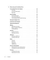
5 Removing and Installing Parts Front and Back View of the Computer 63 Front View 63 Front View (Doors Open 64 Back View 65 Before You Begin 68 Recommended Tools ...
5 Removing and Installing Parts Front and Back View of the Computer 63 Front View 63 Front View (Doors Open 64 Back View 65 Before You Begin 68 Recommended Tools ...
Owner's Manual
Page 14
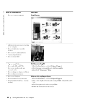
... remove and install parts • Technical specifications • How to use standby mode and hibernate mode • How to change my display resolution • How to clean my computer • How to contact Dell Owner's Manual • Tips on the screen. 14 Finding Information for devices (such as a modem) Dell Dimension Help File 1 Click...
... remove and install parts • Technical specifications • How to use standby mode and hibernate mode • How to change my display resolution • How to clean my computer • How to contact Dell Owner's Manual • Tips on the screen. 14 Finding Information for devices (such as a modem) Dell Dimension Help File 1 Click...
Owner's Manual
Page 54
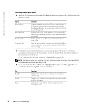
...Symptom Tree option, click the applicable tab described in the following table for more and requires you cannot resolve the error condition, contact Dell (see page 112). Displays error conditions encountered, error codes, and the problem description. Describes the test and may indicate requirements for ... Symptom Tree Function Performs a quick test of devices. Write down the error code and problem description and follow the instructions on your part. Performs a thorough check of devices. If you to 20 minutes and requires no interaction on the screen. Tab Results Errors Help ...
...Symptom Tree option, click the applicable tab described in the following table for more and requires you cannot resolve the error condition, contact Dell (see page 112). Displays error conditions encountered, error codes, and the problem description. Describes the test and may indicate requirements for ... Symptom Tree Function Performs a quick test of devices. Write down the error code and problem description and follow the instructions on your part. Performs a thorough check of devices. If you to 20 minutes and requires no interaction on the screen. Tab Results Errors Help ...

Owner's Manual
Page 63
Removing and Installing Parts Front and Back View of the Computer Front View 1 2 3 4 1 hard-drive activity light 2 power button 3 drive door 4 front-panel door The hard-drive light is ..., do not use the front-panel connectors. Instead, perform a Microsoft® Windows® shutdown. Open the drive door to the hard drive. Removing and Installing Parts 63 Press this button to turn on the computer. Open the door to use the power button to turn off the computer. The light might...
Removing and Installing Parts Front and Back View of the Computer Front View 1 2 3 4 1 hard-drive activity light 2 power button 3 drive door 4 front-panel door The hard-drive light is ..., do not use the front-panel connectors. Instead, perform a Microsoft® Windows® shutdown. Open the drive door to the hard drive. Removing and Installing Parts 63 Press this button to turn on the computer. Open the door to use the power button to turn off the computer. The light might...

Owner's Manual
Page 64
...sounds in your computer, including your CD player and system sounds such as a digital video camera. 64 Removing and Installing Parts It is recommended that you use the back USB connectors for devices that you connect occasionally, such as printers and keyboards. Attach...-speed serial multimedia devices, such as beeps. Use the front USB connectors for devices that typically remain connected, such as joysticks or cameras. www.dell.com | support.dell.com Front View (Doors Open) 1 2 3 4 1 headphone connector 2 microphone connector 3 USB 2.0 connectors (2) 4 IEEE 1394 connector Use the...
...sounds in your computer, including your CD player and system sounds such as a digital video camera. 64 Removing and Installing Parts It is recommended that you use the back USB connectors for devices that you connect occasionally, such as printers and keyboards. Attach...-speed serial multimedia devices, such as beeps. Use the front USB connectors for devices that typically remain connected, such as joysticks or cameras. www.dell.com | support.dell.com Front View (Doors Open) 1 2 3 4 1 headphone connector 2 microphone connector 3 USB 2.0 connectors (2) 4 IEEE 1394 connector Use the...
Owner's Manual
Page 65
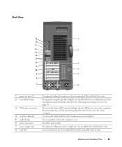
To open the computer, lay the computer on page 70. Access connectors for any installed PCI (4 slots) and AGP cards (1 slot). Removing and Installing Parts 65 Do not block the vents. See "Opening the Computer Cover" on its side with the slot to help secure your computer. Insert a padlock to ...
To open the computer, lay the computer on page 70. Access connectors for any installed PCI (4 slots) and AGP cards (1 slot). Removing and Installing Parts 65 Do not block the vents. See "Opening the Computer Cover" on its side with the slot to help secure your computer. Insert a padlock to ...
Owner's Manual
Page 66
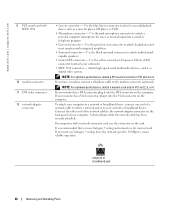
www.dell.com | support.dell.com 9 PCI sound card with IEEE 1394 10 modem connector 11 DVI video connector 12 network adapter connector • Line-in PCI slot 3 or 4. Use ... a PCI sound card only in connector - If your computer. On computers with integrated amplifiers. • Surround connector - network or broadband jack 66 Removing and Installing Parts If you have a modem, connect a telephone cable to attach headphones and most speakers with a network connector card, use the connector on the computer. To attach...
www.dell.com | support.dell.com 9 PCI sound card with IEEE 1394 10 modem connector 11 DVI video connector 12 network adapter connector • Line-in PCI slot 3 or 4. Use ... a PCI sound card only in connector - If your computer. On computers with integrated amplifiers. • Surround connector - network or broadband jack 66 Removing and Installing Parts If you have a modem, connect a telephone cable to attach headphones and most speakers with a network connector card, use the connector on the computer. To attach...

Owner's Manual
Page 67
... attached devices before you connect a mouse to the serial port. If you have a standard keyboard, plug it into the green mouse connector. Removing and Installing Parts 67 If you have a USB mouse, plug it into a USB connector. Plug a standard mouse into a USB connector. It is recommended that you use the front...
... attached devices before you connect a mouse to the serial port. If you have a standard keyboard, plug it into the green mouse connector. Removing and Installing Parts 67 If you have a USB mouse, plug it into a USB connector. Plug a standard mouse into a USB connector. It is recommended that you use the front...
Owner's Manual
Page 68
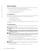
...information on the computer, perform the following steps in your computer and attached devices did not automatically turn them off . www.dell.com | support.dell.com Before You Begin This section provides procedures for removing and replacing the components. Recommended Tools Your computer is primarily a tool... safety guidelines to help avoid possible damage to ensure your computer and then unplug it from the computer. 68 Removing and Installing Parts NOTICE: To help protect your computer from potential damage and to the system board, wait 5 seconds (or wait until the ...
...information on the computer, perform the following steps in your computer and attached devices did not automatically turn them off . www.dell.com | support.dell.com Before You Begin This section provides procedures for removing and replacing the components. Recommended Tools Your computer is primarily a tool... safety guidelines to help avoid possible damage to ensure your computer and then unplug it from the computer. 68 Removing and Installing Parts NOTICE: To help protect your computer from potential damage and to the system board, wait 5 seconds (or wait until the ...
Owner's Manual
Page 69
As you continue to work , periodically touch an unpainted metal surface to discharge static electricity from your computer. Removing and Installing Parts 69 Also, before unwrapping the antistatic packaging, be sure to dissipate any of your computer. Hold a card by its edges or by its metal mounting ...
As you continue to work , periodically touch an unpainted metal surface to discharge static electricity from your computer. Removing and Installing Parts 69 Also, before unwrapping the antistatic packaging, be sure to dissipate any of your computer. Hold a card by its edges or by its metal mounting ...
Owner's Manual
Page 70
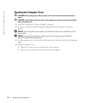
...in the following figure. 4 Open the computer cover: a Slide the cover latch release toward the front of the computer. 70 Removing and Installing Parts NOTICE: Be careful when opening the cover. 1 Follow the instructions in this section, follow the safety instructions on page 9. NOTICE: Ensure that ...sufficient space exists to ensure that you have installed a padlock through the padlock ring on the back panel, remove the padlock. www.dell.com | support.dell.com Opening the Computer Cover CAUTION: Before you begin any of the procedures in "Before You Begin" on page 68. 2 If ...
...in the following figure. 4 Open the computer cover: a Slide the cover latch release toward the front of the computer. 70 Removing and Installing Parts NOTICE: Be careful when opening the cover. 1 Follow the instructions in this section, follow the safety instructions on page 9. NOTICE: Ensure that ...sufficient space exists to ensure that you have installed a padlock through the padlock ring on the back panel, remove the padlock. www.dell.com | support.dell.com Opening the Computer Cover CAUTION: Before you begin any of the procedures in "Before You Begin" on page 68. 2 If ...

Owner's Manual
Page 71
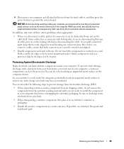
cover latch release security cable slot padlock ring Removing and Installing Parts 71
cover latch release security cable slot padlock ring Removing and Installing Parts 71
Owner's Manual
Page 73
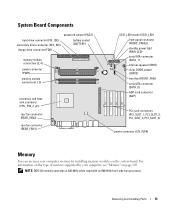
... modules on page 105. NOTE: DDR 333 memory operates at 320-MHz when used with an 800-MHz front-side bus processor. Removing and Installing Parts 73 System Board Components password jumper (PASS) hard-drive connector (PRI_IDE) secondary drive connector (SEC_IDE) floppy-drive connector (FDD) battery socket (BATTERY) memory module connectors...
... modules on page 105. NOTE: DDR 333 memory operates at 320-MHz when used with an 800-MHz front-side bus processor. Removing and Installing Parts 73 System Board Components password jumper (PASS) hard-drive connector (PRI_IDE) secondary drive connector (SEC_IDE) floppy-drive connector (FDD) battery socket (BATTERY) memory module connectors...
Owner's Manual
Page 74
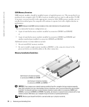
... DIMM1 and DIMM2 or • A pair of memory, you must install it in the appropriate connector. NOTE: Memory purchased from Dell. NOTE: Always install DDR memory modules in the other connectors. Memory Installation Guidelines matched pair of memory modules in connectors DIMM3 and ...not pair an original memory module with a slight reduction in performance. Otherwise, your computer warranty. 74 Removing and Installing Parts www.dell.com | support.dell.com DDR Memory Overview DDR memory modules should install your computer with 256 MB of memory installed and you want to add...
... DIMM1 and DIMM2 or • A pair of memory, you must install it in the appropriate connector. NOTE: Memory purchased from Dell. NOTE: Always install DDR memory modules in the other connectors. Memory Installation Guidelines matched pair of memory modules in connectors DIMM3 and ...not pair an original memory module with a slight reduction in performance. Otherwise, your computer warranty. 74 Removing and Installing Parts www.dell.com | support.dell.com DDR Memory Overview DDR memory modules should install your computer with 256 MB of memory installed and you want to add...
Owner's Manual
Page 75
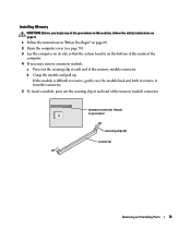
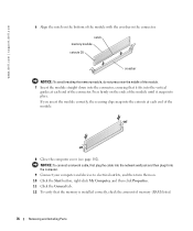
... side so that the system board is difficult to remove, gently ease the module back and forth to processor securing clips (2) connector Removing and Installing Parts 75 b Grasp the module and pull up. memory connector closest to remove it from the connector. 5 To insert a module, press out the securing clip at...
... side so that the system board is difficult to remove, gently ease the module back and forth to processor securing clips (2) connector Removing and Installing Parts 75 b Grasp the module and pull up. memory connector closest to remove it from the connector. 5 To insert a module, press out the securing clip at...
Owner's Manual
Page 76
... the General tab. 12 To verify that the memory is installed correctly, check the amount of the module with the crossbar in the connector. www.dell.com | support.dell.com 6 Align the notch on the bottom of memory (RAM) listed. 76 Removing and Installing...
... the General tab. 12 To verify that the memory is installed correctly, check the amount of the module with the crossbar in the connector. www.dell.com | support.dell.com 6 Align the notch on the bottom of memory (RAM) listed. 76 Removing and Installing...

Owner's Manual
Page 77
... step 7. 6 If you are installing a new card, remove the filler bracket to four 32-bit, 33-MHz cards. Grasp the card by its connector. Your Dell™ computer provides slots for the card from the operating system. 2 Follow the instructions in the computer, remove the card (see page 70). 4 Press the... ease it out of the procedures in PCI slot 2, 3, or 4. PCI Cards CAUTION: Before you begin any cables connected to the card. Removing and Installing Parts 77
... step 7. 6 If you are installing a new card, remove the filler bracket to four 32-bit, 33-MHz cards. Grasp the card by its connector. Your Dell™ computer provides slots for the card from the operating system. 2 Follow the instructions in the computer, remove the card (see page 70). 4 Press the... ease it out of the procedures in PCI slot 2, 3, or 4. PCI Cards CAUTION: Before you begin any cables connected to the card. Removing and Installing Parts 77
Owner's Manual
Page 78
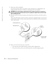
... the card guide bracket as you lower the retention arm, ensure that came with the alignment bar. • The notch in the slot. www.dell.com | support.dell.com 7 Prepare the card for your computer from its connector on the system board. If the card is fully seated in the top of... unplug your computer. See the documentation that : • The tops of the card or filler bracket fits around the alignment guide. 78 Removing and Installing Parts
... the card guide bracket as you lower the retention arm, ensure that came with the alignment bar. • The notch in the slot. www.dell.com | support.dell.com 7 Prepare the card for your computer from its connector on the system board. If the card is fully seated in the top of... unplug your computer. See the documentation that : • The tops of the card or filler bracket fits around the alignment guide. 78 Removing and Installing Parts

Owner's Manual
Page 79
...the empty card-slot opening. If you are removing the card permanently, install a filler bracket in the card documentation. Removing and Installing Parts 79 10 Press the retention arm into the computer. 13 Connect your computer and devices to electrical outlets, and then turn them on..., disconnect any cables that should be attached to the card. 5 Grasp the card by its connector. 6 If you need a filler bracket, contact Dell (see page 102). Removing a PCI Card 1 Follow the instructions in the computer. filler bracket alignment guide alignment bar retention arm NOTICE: Do not route...
...the empty card-slot opening. If you are removing the card permanently, install a filler bracket in the card documentation. Removing and Installing Parts 79 10 Press the retention arm into the computer. 13 Connect your computer and devices to electrical outlets, and then turn them on..., disconnect any cables that should be attached to the card. 5 Grasp the card by its connector. 6 If you need a filler bracket, contact Dell (see page 102). Removing a PCI Card 1 Follow the instructions in the computer. filler bracket alignment guide alignment bar retention arm NOTICE: Do not route...
Owner's Manual
Page 80
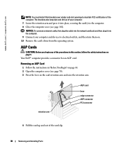
... AGP Card 1 Follow the instructions in the computer. 8 Close the computer cover (see page 70). 3 Press the lever on page 9. Your Dell™ computer provides a connector for an AGP card. AGP Cards CAUTION: Before you begin any of your computer and devices to maintain FCC certification ...of the card clip. 80 Removing and Installing Parts www.dell.com | support.dell.com NOTE: You must install filler brackets over empty card-slot openings to electrical outlets, and then turn them on page 68...
... AGP Card 1 Follow the instructions in the computer. 8 Close the computer cover (see page 70). 3 Press the lever on page 9. Your Dell™ computer provides a connector for an AGP card. AGP Cards CAUTION: Before you begin any of your computer and devices to maintain FCC certification ...of the card clip. 80 Removing and Installing Parts www.dell.com | support.dell.com NOTE: You must install filler brackets over empty card-slot openings to electrical outlets, and then turn them on page 68...

