User Guide
Page 3
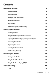
..., Swivel, and Vertical Extension 25 Adjusting the Rotation Display Settings of Your System 26 Connecting Your Monitor 26 Organizing Your Cables 30 Removing the Monitor Stand 30 Wall Mounting (Optional 31 Operating the Monitor 32 Turning on the Monitor 32 Using the Front Panel Controls 32 Using the On-Screen Display (OSD) Menu 35...
..., Swivel, and Vertical Extension 25 Adjusting the Rotation Display Settings of Your System 26 Connecting Your Monitor 26 Organizing Your Cables 30 Removing the Monitor Stand 30 Wall Mounting (Optional 31 Operating the Monitor 32 Turning on the Monitor 32 Using the Front Panel Controls 32 Using the On-Screen Display (OSD) Menu 35...
User Guide
Page 4
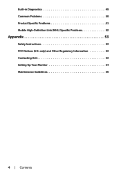
only) and Other Regulatory Information 53 Contacting Dell 53 Setting Up Your Monitor 54 Maintenance Guidelines 56 4 | Contents Built-in Diagnostics 49 Common Problems 50 Product Specific Problems 51 Mobile High-Definition Link (MHL) Specific Problems 52 Appendix 53 Safety Instructions 53 FCC Notices (U.S.
only) and Other Regulatory Information 53 Contacting Dell 53 Setting Up Your Monitor 54 Maintenance Guidelines 56 4 | Contents Built-in Diagnostics 49 Common Problems 50 Product Specific Problems 51 Mobile High-Definition Link (MHL) Specific Problems 52 Appendix 53 Safety Instructions 53 FCC Notices (U.S.
User Guide
Page 5
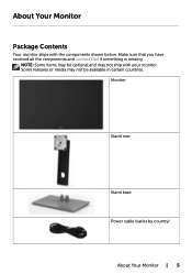
Monitor Stand riser Stand base Power cable (varies by country) About Your Monitor | 5 About Your Monitor Package Contents Your monitor ships with your monitor. Some features or media may not be optional and may be available in certain countries. Make sure that you have received all the components and contact Dell if something is missing. NOTE: Some items may not ship with the components shown below.
Monitor Stand riser Stand base Power cable (varies by country) About Your Monitor | 5 About Your Monitor Package Contents Your monitor ships with your monitor. Some features or media may not be optional and may be available in certain countries. Make sure that you have received all the components and contact Dell if something is missing. NOTE: Some items may not ship with the components shown below.
User Guide
Page 6
... media • Quick Setup Guide • Safety and Regulatory Information • Factory Calibration Report Product Features The Dell UltraSharp U2417H monitor has an active matrix, thinfilm transistor (TFT), liquid crystal display (LCD), and LED backlight. The monitor features include: • 60.47 cm (23.8-inch) active area display (Measured diagonally) 1920 x 1080 resolution, plus...
... media • Quick Setup Guide • Safety and Regulatory Information • Factory Calibration Report Product Features The Dell UltraSharp U2417H monitor has an active matrix, thinfilm transistor (TFT), liquid crystal display (LCD), and LED backlight. The monitor features include: • 60.47 cm (23.8-inch) active area display (Measured diagonally) 1920 x 1080 resolution, plus...
User Guide
Page 7
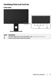
Identifying Parts and Controls Front view Label 1 2 Description Function buttons (For more information, see Operating the Monitor) Power on/off button (with LED indicator) About Your Monitor | 7
Identifying Parts and Controls Front view Label 1 2 Description Function buttons (For more information, see Operating the Monitor) Power on/off button (with LED indicator) About Your Monitor | 7
User Guide
Page 8
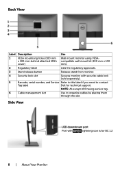
...-behind attached VESA compatible wall mount kit (100 mm x 100 cover) mm). 2 Regulatory label Lists the regulatory approvals. 3 Stand release button Release stand from monitor. 4 Security lock slot Secures monitor with lightning icon is for technical support. NOTE: All except APJ having service tag. 6 Cable management slot Use to contact Tag label...
...-behind attached VESA compatible wall mount kit (100 mm x 100 cover) mm). 2 Regulatory label Lists the regulatory approvals. 3 Stand release button Release stand from monitor. 4 Security lock slot Secures monitor with lightning icon is for technical support. NOTE: All except APJ having service tag. 6 Cable management slot Use to contact Tag label...
User Guide
Page 9
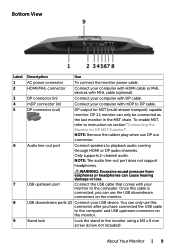
...is connected, you can only use this connector after you have connected the USB cable to instruction on the monitor. You can use DP out connector. DP 1.1 monitor can cause hearing damage or loss. To enable MST, refer to the computer and USB upstream connector on... section "Connecting the Monitor for MST (multi-stream transport) capable monitor. Only supports 2-channel audio. About Your Monitor | 9 USB upstream port WARNING: Excessive sound pressure from earphones or headphones can only be ...
...is connected, you can only use this connector after you have connected the USB cable to instruction on the monitor. You can use DP out connector. DP 1.1 monitor can cause hearing damage or loss. To enable MST, refer to the computer and USB upstream connector on... section "Connecting the Monitor for MST (multi-stream transport) capable monitor. Only supports 2-channel audio. About Your Monitor | 9 USB upstream port WARNING: Excessive sound pressure from earphones or headphones can only be ...
User Guide
Page 10
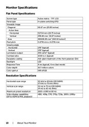
Monitor Specifications Flat Panel Specifications Screen type Panel type Viewable image Diagonal Active Area Horizontal Vertical Area Pixel pitch Viewing angle Horizontal Vertical Luminance output Contrast ... 75 Hz (DP/HDMI) 24 Hz to 60 Hz (MHL) 1920 x 1080 at 60 Hz 480i, 480p, 576i, 576p, 720p, 1080i, 1080p 10 | About Your Monitor
Monitor Specifications Flat Panel Specifications Screen type Panel type Viewable image Diagonal Active Area Horizontal Vertical Area Pixel pitch Viewing angle Horizontal Vertical Luminance output Contrast ... 75 Hz (DP/HDMI) 24 Hz to 60 Hz (MHL) 1920 x 1080 at 60 Hz 480i, 480p, 576i, 576p, 720p, 1080i, 1080p 10 | About Your Monitor
User Guide
Page 12
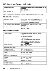
....2 mm (1.78 inches) 400.1 mm (15.75 inches) 12 | About Your Monitor MST Multi-Stream Transport (MST) Modes MST Source Monitor 1920 x 1080/60 Hz Maximum number of external monitor that can be supported 1920 x 1080/60 Hz 2 NOTE: Maximum external monitor resolution supported is for each differential line Per differential line at 100...
....2 mm (1.78 inches) 400.1 mm (15.75 inches) 12 | About Your Monitor MST Multi-Stream Transport (MST) Modes MST Source Monitor 1920 x 1080/60 Hz Maximum number of external monitor that can be supported 1920 x 1080/60 Hz 2 NOTE: Maximum external monitor resolution supported is for each differential line Per differential line at 100...

User Guide
Page 13
...) 5% to 90% (non-condensing) 5,000 m (16,404 ft) (maximum) 12,192 m (40,000 ft) (maximum) 232 BTU/hour (maximum) 64.8 BTU/hour (typical) About Your Monitor | 13 Height (compressed) 336.2 mm(13.24 inches) Width 272.6 mm (10.73 inches) Depth 188 mm (7.40 inches) Weight Weight with packaging 7.35 kg...
...) 5% to 90% (non-condensing) 5,000 m (16,404 ft) (maximum) 12,192 m (40,000 ft) (maximum) 232 BTU/hour (maximum) 64.8 BTU/hour (typical) About Your Monitor | 13 Height (compressed) 336.2 mm(13.24 inches) Width 272.6 mm (10.73 inches) Depth 188 mm (7.40 inches) Weight Weight with packaging 7.35 kg...

User Guide
Page 14
...tolerances or otherwise. If you press any button in use. This document is tested at 230 Volts / 50 Hz. NOTE: This monitor is expressed or implied. No warranty as power save mode*. Your product may perform differently, depending on the software, components and ... Active-off mode Switch off mode, one of this information in the normal operation mode. If the computer detects input from the monitor. **Maximum power consumption with maximum luminance. *** Energy consumption (On Mode) is informational only and reflects laboratory performance. Inactive Off - -...
...tolerances or otherwise. If you press any button in use. This document is tested at 230 Volts / 50 Hz. NOTE: This monitor is expressed or implied. No warranty as power save mode*. Your product may perform differently, depending on the software, components and ... Active-off mode Switch off mode, one of this information in the normal operation mode. If the computer detects input from the monitor. **Maximum power consumption with maximum luminance. *** Energy consumption (On Mode) is informational only and reflects laboratory performance. Inactive Off - -...
User Guide
Page 15
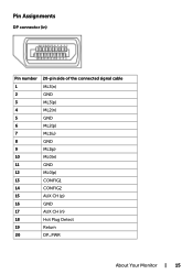
Pin Assignments DP connector (in) Pin number 20-pin side of the connected signal cable 1 ML3(n) 2 GND 3 ML3(p) 4 ML2(n) 5 GND 6 ML2(p) 7 ML1(u) 8 GND 9 ML1(p) 10 ML0(n) 11 GND 12 ML0(p) 13 CONFIG1 14 CONFIG2 15 AUX CH (p) 16 GND 17 AUX CH (n) 18 Hot Plug Detect 19 Return 20 DP_PWR About Your Monitor | 15
Pin Assignments DP connector (in) Pin number 20-pin side of the connected signal cable 1 ML3(n) 2 GND 3 ML3(p) 4 ML2(n) 5 GND 6 ML2(p) 7 ML1(u) 8 GND 9 ML1(p) 10 ML0(n) 11 GND 12 ML0(p) 13 CONFIG1 14 CONFIG2 15 AUX CH (p) 16 GND 17 AUX CH (n) 18 Hot Plug Detect 19 Return 20 DP_PWR About Your Monitor | 15
User Guide
Page 16
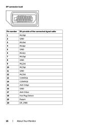
DP connector (out) Pin number 20-pin side of the connected signal cable 1 ML0(p) 2 GND 3 ML0(n) 4 ML1(p) 5 GND 6 ML1(n) 7 ML2(p) 8 GND 9 ML2(n) 10 ML3(p) 11 GND 12 ML3(n) 13 CONFIG1 14 CONFIG2 15 AUX CH(p) 16 GND 17 AUX CH(n) 18 Hot Plug Detect 19 Return 20 DP_PWR 16 | About Your Monitor
DP connector (out) Pin number 20-pin side of the connected signal cable 1 ML0(p) 2 GND 3 ML0(n) 4 ML1(p) 5 GND 6 ML1(n) 7 ML2(p) 8 GND 9 ML2(n) 10 ML3(p) 11 GND 12 ML3(n) 13 CONFIG1 14 CONFIG2 15 AUX CH(p) 16 GND 17 AUX CH(n) 18 Hot Plug Detect 19 Return 20 DP_PWR 16 | About Your Monitor
User Guide
Page 17
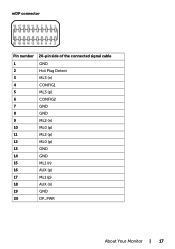
mDP connector Pin number 20-pin side of the connected signal cable 1 GND 2 Hot Plug Detect 3 ML3 (n) 4 CONFIG1 5 ML3 (p) 6 CONFIG2 7 GND 8 GND 9 ML2 (n) 10 ML0 (p) 11 ML2 (p) 12 ML0 (p) 13 GND 14 GND 15 ML1 (n) 16 AUX (p) 17 ML1 (p) 18 AUX (n) 19 GND 20 DP_PWR About Your Monitor | 17
mDP connector Pin number 20-pin side of the connected signal cable 1 GND 2 Hot Plug Detect 3 ML3 (n) 4 CONFIG1 5 ML3 (p) 6 CONFIG2 7 GND 8 GND 9 ML2 (n) 10 ML0 (p) 11 ML2 (p) 12 ML0 (p) 13 GND 14 GND 15 ML1 (n) 16 AUX (p) 17 ML1 (p) 18 AUX (n) 19 GND 20 DP_PWR About Your Monitor | 17
User Guide
Page 18
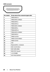
HDMI connector Pin number 1 2 3 4 5 6 7 8 9 10 11 12 13 14 15 16 17 18 19 19-pin side of the connected signal cable TMDS DATA 2+ TMDS DATA 2 SHIELD TMDS DATA 2TMDS DATA 1+ TMDS DATA 1 SHIELD TMDS DATA 1TMDS DATA 0+ TMDS DATA 0 SHIELD TMDS DATA 0TMDS CLOCK+ TMDS CLOCK SHIELD TMDS CLOCKCEC Reserved (N.C. on device) DDC CLOCK (SCL) DDC DATA (SDA) DDC/CEC Ground +5 V POWER HOT PLUG DETECT 18 | About Your Monitor
HDMI connector Pin number 1 2 3 4 5 6 7 8 9 10 11 12 13 14 15 16 17 18 19 19-pin side of the connected signal cable TMDS DATA 2+ TMDS DATA 2 SHIELD TMDS DATA 2TMDS DATA 1+ TMDS DATA 1 SHIELD TMDS DATA 1TMDS DATA 0+ TMDS DATA 0 SHIELD TMDS DATA 0TMDS CLOCK+ TMDS CLOCK SHIELD TMDS CLOCKCEC Reserved (N.C. on device) DDC CLOCK (SCL) DDC DATA (SDA) DDC/CEC Ground +5 V POWER HOT PLUG DETECT 18 | About Your Monitor

User Guide
Page 19
MHL connector Pin number 19-pin side of the connected signal cable 1 N/C 2 CD_SENSE 3 N/C 4 N/C 5 TMDS_GND 6 N/C 7 MHL+ 8 MHL_Shield 9 MHL- 10 N/C 11 TMDS_GND 12 N/C 13 N/C 14 N/C 15 CD_PULLUP 16 N/C 17 VBUS_CBUS_GND 18 VBUS 19 CBUS 2Shell Shield About Your Monitor | 19
MHL connector Pin number 19-pin side of the connected signal cable 1 N/C 2 CD_SENSE 3 N/C 4 N/C 5 TMDS_GND 6 N/C 7 MHL+ 8 MHL_Shield 9 MHL- 10 N/C 11 TMDS_GND 12 N/C 13 N/C 14 N/C 15 CD_PULLUP 16 N/C 17 VBUS_CBUS_GND 18 VBUS 19 CBUS 2Shell Shield About Your Monitor | 19
User Guide
Page 20
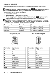
... port Pin number 1 2 3 4 5 6 7 8 9 Shell Signal name VBUS DD+ GND StdB_SSTXStdB_SSTX+ GND_DRAIN StdB_SSRXStdB_SSRX+ Shield 20 | About Your Monitor Pin number 1 2 3 4 5 6 7 8 9 Shell Signal name VBUS DD+ GND StdA_SSRXStdA_SSRX+ GND_DRAIN StdA_SSTXStdA_SSTX+ Shield Universal Serial Bus (USB) This section gives you turn off ...up to resume normal functionality. supports fast current charging capability if the device is on your monitor. NOTE: The monitor's USB ports work only when the monitor is BC 1.2 compatible. If you information about the USB ports available on or in the ...
... port Pin number 1 2 3 4 5 6 7 8 9 Shell Signal name VBUS DD+ GND StdB_SSTXStdB_SSTX+ GND_DRAIN StdB_SSRXStdB_SSRX+ Shield 20 | About Your Monitor Pin number 1 2 3 4 5 6 7 8 9 Shell Signal name VBUS DD+ GND StdA_SSRXStdA_SSRX+ GND_DRAIN StdA_SSTXStdA_SSTX+ Shield Universal Serial Bus (USB) This section gives you turn off ...up to resume normal functionality. supports fast current charging capability if the device is on your monitor. NOTE: The monitor's USB ports work only when the monitor is BC 1.2 compatible. If you information about the USB ports available on or in the ...
User Guide
Page 21
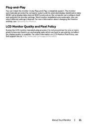
For more information about changing the monitor settings, see Dell support site at: http://www.dell.com/support/monitors. For more pixels to see and do not affect the display quality or usability. About Your Monitor | 21 Most monitor installations are hard to become fixed in any Plug-and-Play-compatible system. you can configure itself and...
For more information about changing the monitor settings, see Dell support site at: http://www.dell.com/support/monitors. For more pixels to see and do not affect the display quality or usability. About Your Monitor | 21 Most monitor installations are hard to become fixed in any Plug-and-Play-compatible system. you can configure itself and...

User Guide
Page 22
... the Stand NOTE: The stand riser and stand base are detached when the monitor is applicable for the default stand. To attach the monitor stand: 1 Remove the monitor protective cover and place the moitor with the stand to set it . 2 Insert the two tabs on the upper part of the stand to the... groove on it up. NOTE: The procedure below is shipped from the factory. CAUTION: Place monitor of the monitor. 3 Press the stand down till it snaps into its front facing downward on the back of a flat, clean, and soft surface to avoid scratching...
... the Stand NOTE: The stand riser and stand base are detached when the monitor is applicable for the default stand. To attach the monitor stand: 1 Remove the monitor protective cover and place the moitor with the stand to set it . 2 Insert the two tabs on the upper part of the stand to the... groove on it up. NOTE: The procedure below is shipped from the factory. CAUTION: Place monitor of the monitor. 3 Press the stand down till it snaps into its front facing downward on the back of a flat, clean, and soft surface to avoid scratching...

User Guide
Page 23
Setting Up the Monitor | 23 • Hold the stand base with the triangle mark facing upward. • Align the stand base protruded blocks to the matching slot on the stand. • Insert the stand base blocks fully into the stand slot.
Setting Up the Monitor | 23 • Hold the stand base with the triangle mark facing upward. • Align the stand base protruded blocks to the matching slot on the stand. • Insert the stand base blocks fully into the stand slot.


