
Dell Networking Installation Guide
Page 3
... Features 10 Physical Dimensions 11 Chassis Ports 11 Determine System Status 11 LED Displays 11 Basic Installation Requirements 14 Orderable S6000 Components 15 3 Site Location and Preparation Site Selection 18 Cabinet Placement 18 Rack Mount 18 Ground 18 Fans and Airflow... Rack or Cabinet Hardware 22 Rack Mount Safety Considerations 22 Installing the Dell ReadyRails System 23 Configuring a Two-Post Flush-Mount 24 Configuring a Two-Post Center-Mount 25 Configure a Four-Post Thread 26 Installing the S6000 System 27 Installing a 1U Front-Rack 27 Attaching the Ground Cable ...
... Features 10 Physical Dimensions 11 Chassis Ports 11 Determine System Status 11 LED Displays 11 Basic Installation Requirements 14 Orderable S6000 Components 15 3 Site Location and Preparation Site Selection 18 Cabinet Placement 18 Rack Mount 18 Ground 18 Fans and Airflow... Rack or Cabinet Hardware 22 Rack Mount Safety Considerations 22 Installing the Dell ReadyRails System 23 Configuring a Two-Post Flush-Mount 24 Configuring a Two-Post Center-Mount 25 Configure a Four-Post Thread 26 Installing the S6000 System 27 Installing a 1U Front-Rack 27 Attaching the Ground Cable ...

Dell Networking Installation Guide
Page 4
www.dell.com | support.dell.com 4| Split QSFP+ Ports to SFP+ Ports 31 Important Points to Know 31 Power Up the S6000 System 32 Power Up Sequence 32 5 Power Supplies Components 33 Installing an AC or DC Power Supply 34 Replacing an AC or DC ... a Fan Module 38 Replacing a Fan Module 38 7 Management Ports Accessing the RS-232 Console Port 39 Accessing the USB-B Console Port 40 Default Configuration 41 8 Specifications Chassis Physical Design 43 Environmental Parameters 43 Power Requirements 44 AC Input Specification 44 DC Input Specification 44 IEEE Standards 44 Agency Compliance...
www.dell.com | support.dell.com 4| Split QSFP+ Ports to SFP+ Ports 31 Important Points to Know 31 Power Up the S6000 System 32 Power Up Sequence 32 5 Power Supplies Components 33 Installing an AC or DC Power Supply 34 Replacing an AC or DC ... a Fan Module 38 Replacing a Fan Module 38 7 Management Ports Accessing the RS-232 Console Port 39 Accessing the USB-B Console Port 40 Default Configuration 41 8 Specifications Chassis Physical Design 43 Environmental Parameters 43 Power Requirements 44 AC Input Specification 44 DC Input Specification 44 IEEE Standards 44 Agency Compliance...

Dell Networking Installation Guide
Page 7
... radiation. After you have any questions regarding FTOS versions and system upgrades, contact Dell Technical Support. If you install and power up of the S6000, for software configuration information, refer to the FTOS Configuration Guide for the S6000 System and for the S6000 System. This equipment contains two power cords. Read this guide before servicing. CAUTION...
... radiation. After you have any questions regarding FTOS versions and system upgrades, contact Dell Technical Support. If you install and power up of the S6000, for software configuration information, refer to the FTOS Configuration Guide for the S6000 System and for the S6000 System. This equipment contains two power cords. Read this guide before servicing. CAUTION...

Dell Networking Installation Guide
Page 9
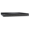
... the PSU and fan modules. PSU 0 2 - Introduction The S6000 is a fully featured switch/router one rack unit (RU) system that you can deploy as a spine, leaf, or top of rack (ToR) device where you can use to create a configuration of 96 ports of 10G small form-factor pluggable plus (SFP...+) (using breakout cables) and eight ports of 40G that you require 10Gb and/or 40Gb connections. 2 The S6000 System This chapter contains general features, capabilities, and physical...
... the PSU and fan modules. PSU 0 2 - Introduction The S6000 is a fully featured switch/router one rack unit (RU) system that you can deploy as a spine, leaf, or top of rack (ToR) device where you can use to create a configuration of 96 ports of 10G small form-factor pluggable plus (SFP...+) (using breakout cables) and eight ports of 40G that you require 10Gb and/or 40Gb connections. 2 The S6000 System This chapter contains general features, capabilities, and physical...

Dell Networking Installation Guide
Page 11
...list the LED definitions for the S6000 System. This includes the system, PSU, and fan status. For more information about these options, refer to the FTOS Command Line Reference Guide for the S6000 System and the FTOS Configuration Guide for the S6000 system. LED Displays As shown in... several ways, including LEDs and boot menu options. The S6000 System | 11 • Temperature monitoring • Software-readable thermal ...
...list the LED definitions for the S6000 System. This includes the system, PSU, and fan status. For more information about these options, refer to the FTOS Command Line Reference Guide for the S6000 System and the FTOS Configuration Guide for the S6000 system. LED Displays As shown in... several ways, including LEDs and boot menu options. The S6000 System | 11 • Temperature monitoring • Software-readable thermal ...

Dell Networking Installation Guide
Page 13
... Yellow - I /O side LOCATOR LED • Off - Fan powered and running at the expected rpm. MASTER LED • Solid green - The S6000 System | 13 Table 2-1. Displays summary of differing airflows are created. One of all four LEDs are used . System in progress. • Solid green... • Solid green - Normal operation. I /O side • Solid yellow - No power. • Blinking blue - I /O side Power LED • Off - When configured as a 40G port, only the first of the FAN LEDs on the utility side indicates failure, the fan LED on ports 4, 12, 20, 28, 100...
... Yellow - I /O side LOCATOR LED • Off - Fan powered and running at the expected rpm. MASTER LED • Solid green - The S6000 System | 13 Table 2-1. Displays summary of differing airflows are created. One of all four LEDs are used . System in progress. • Solid green... • Solid green - Normal operation. I /O side • Solid yellow - No power. • Blinking blue - I /O side Power LED • Off - When configured as a 40G port, only the first of the FAN LEDs on the utility side indicates failure, the fan LED on ports 4, 12, 20, 28, 100...

Dell Networking Installation Guide
Page 14
... list of components required for a successful installation of the S6000: • S6000 chassis • If you ordered AC units, cables to connect the AC power source to each of the chassis' AC power supplies (country/regional configured) • If you ordered DC units, cables to ... in Chapter 3, Site Location and Preparation and Chapter 4, Install the S6000. Table 2-3. No Link. • Blinking green - However, here is active. • Solid green - Link up at 40Gbps/10Gbps speed. www.dell.com | support.dell.com Table 2-2. 40G QSFP+/ 4x10G SFP+ Ethernet Port LEDs Feature Detailed...
... list of components required for a successful installation of the S6000: • S6000 chassis • If you ordered AC units, cables to connect the AC power source to each of the chassis' AC power supplies (country/regional configured) • If you ordered DC units, cables to ... in Chapter 3, Site Location and Preparation and Chapter 4, Install the S6000. Table 2-3. No Link. • Blinking green - However, here is active. • Solid green - Link up at 40Gbps/10Gbps speed. www.dell.com | support.dell.com Table 2-2. 40G QSFP+/ 4x10G SFP+ Ethernet Port LEDs Feature Detailed...

Dell Networking Installation Guide
Page 15
... order optional modules and optics separately. The following is a list of different configurations and modules: • S6000 AC Normal Airflow: 32 40Gbps QSFP+ ports, 2 AC power supply and 3 fan subsystems (airflow from the I/O side to the PSU side) • S6000 AC Reverse Airflow: 32 40Gbps QSFP+ ports, 2 AC power supply and... Normal Airflow: 32 40Gbps QSFP+ ports, 2 DC power supply and 3 fan subsystems (airflow from the I/O side to the PSU side) • S6000 AC Reverse Airflow: 32 40Gbps QSFP+ ports, 2 DC power supply and 3 fan subsystems (airflow from the PSU side to the I/O side) •...
... order optional modules and optics separately. The following is a list of different configurations and modules: • S6000 AC Normal Airflow: 32 40Gbps QSFP+ ports, 2 AC power supply and 3 fan subsystems (airflow from the I/O side to the PSU side) • S6000 AC Reverse Airflow: 32 40Gbps QSFP+ ports, 2 AC power supply and... Normal Airflow: 32 40Gbps QSFP+ ports, 2 DC power supply and 3 fan subsystems (airflow from the I/O side to the PSU side) • S6000 AC Reverse Airflow: 32 40Gbps QSFP+ ports, 2 DC power supply and 3 fan subsystems (airflow from the PSU side to the I/O side) •...

Dell Networking Installation Guide
Page 19
... system. When installing AC systems, follow the requirements of the FTOS Command Ling Reference Guide for the S6000 System and FTOS Configuration Guide for the S6000 System. The S6000 supports three fan trays with fan airflow from the I/O to the utility or the utility to the applicable... disconnect the power cable before you are ready to 58°C. The S6000 never intentionally turns off the fans. Storing Components If you do not install your S6000 and components immediately, Dell Networking recommends properly storing the system and all optional components until you service...
... system. When installing AC systems, follow the requirements of the FTOS Command Ling Reference Guide for the S6000 System and FTOS Configuration Guide for the S6000 System. The S6000 supports three fan trays with fan airflow from the I/O to the utility or the utility to the applicable... disconnect the power cable before you are ready to 58°C. The S6000 never intentionally turns off the fans. Storing Components If you do not install your S6000 and components immediately, Dell Networking recommends properly storing the system and all optional components until you service...

Dell Networking Installation Guide
Page 21
.... This chapter describes the installation procedures as follows: • Unpack the S6000 System • Install Rack or Cabinet Hardware • Installing the Dell ReadyRails System • Configuring a Two-Post Flush-Mount • Configuring a Two-Post Center-Mount • Configure a Four-Post Thread • Installing the S6000 System • Installing a 1U Front-Rack • Attaching the Ground...
.... This chapter describes the installation procedures as follows: • Unpack the S6000 System • Install Rack or Cabinet Hardware • Installing the Dell ReadyRails System • Configuring a Two-Post Flush-Mount • Configuring a Two-Post Center-Mount • Configure a Four-Post Thread • Installing the S6000 System • Installing a 1U Front-Rack • Attaching the Ground...

Dell Networking Installation Guide
Page 23
...for the second rail. 4 To remove each rail. Refer to easily configure your rack for installation of the equipment is provided to Figure 4-1, item 2. 3 Repeat this procedure for safe operation of your S6000 system. Pay particular attention to the supply connections other than the direct... connections to Figure 4-1, item 3. Install the S6000 | 23 • Reduced air flow - You can install the ReadyRails system using the 1U tool-less method or one rail between the left and right vertical posts. Installing the Dell ReadyRails System The ReadyRails rack mounting system is...
...for the second rail. 4 To remove each rail. Refer to easily configure your rack for installation of the equipment is provided to Figure 4-1, item 2. 3 Repeat this procedure for safe operation of your S6000 system. Pay particular attention to the supply connections other than the direct... connections to Figure 4-1, item 3. Install the S6000 | 23 • Reduced air flow - You can install the ReadyRails system using the 1U tool-less method or one rail between the left and right vertical posts. Installing the Dell ReadyRails System The ReadyRails rack mounting system is...

Dell Networking Installation Guide
Page 24
...4-2, item 2. 3 Slide the plunger bracket forward against the vertical post and secure the plunger bracket to Figure 4-2, item 3. 4 Repeat this configuration, remove the castings from each front flange ear (on the switch side of each casting, use a Torx driver. Refer to the post flange... castings. Figure 4-2. To remove the two screws from the front side of the rail) and remove each ReadyRails assembly. www.dell.com | support.dell.com Configuring a Two-Post Flush-Mount Step Task 1 For this procedure for future rack requirements. Retain the castings for the second rail....
...4-2, item 2. 3 Slide the plunger bracket forward against the vertical post and secure the plunger bracket to Figure 4-2, item 3. 4 Repeat this configuration, remove the castings from each front flange ear (on the switch side of each casting, use a Torx driver. Refer to the post flange... castings. Figure 4-2. To remove the two screws from the front side of the rail) and remove each ReadyRails assembly. www.dell.com | support.dell.com Configuring a Two-Post Flush-Mount Step Task 1 For this procedure for future rack requirements. Retain the castings for the second rail....

Dell Networking Installation Guide
Page 25
Two-Post Center-Mount Configuration 2 Slide the back bracket towards the post and secure it clicks into place and secure the bracket to the front post flange with two user-supplied screws. Configuring a Two-Post Center-Mount Step Task 1 Slide the plunger bracket rearward until it to the post flange with two user-supplied screws. Install the S6000 | 25 Figure 4-3. Refer to Figure 4-3, item 1. Refer to Figure 4-3, item 2. 3 Repeat this procedure for the second rail.
Two-Post Center-Mount Configuration 2 Slide the back bracket towards the post and secure it clicks into place and secure the bracket to the front post flange with two user-supplied screws. Configuring a Two-Post Center-Mount Step Task 1 Slide the plunger bracket rearward until it to the post flange with two user-supplied screws. Install the S6000 | 25 Figure 4-3. Refer to Figure 4-3, item 1. Refer to Figure 4-3, item 2. 3 Repeat this procedure for the second rail.

Dell Networking Installation Guide
Page 26
Four-Post Threaded Configuration 26 | Install the S6000 Retain the castings for future rack requirements. 2 For each rail, attach the front and rear flanges to Figure , item 2. To remove the two screws from each end of the ReadyRails assemblies. Figure 4-4. Refer to the post flanges with two user-supplied screws at each end. Refer to Figure , item 1. www.dell.com | support.dell.com Configure a Four-Post Thread Step Task 1 For this configuration, remove the flange ear castings from each flange ear and remove each casting, use a Torx driver.
Four-Post Threaded Configuration 26 | Install the S6000 Retain the castings for future rack requirements. 2 For each rail, attach the front and rear flanges to Figure , item 2. To remove the two screws from each end of the ReadyRails assemblies. Figure 4-4. Refer to the post flanges with two user-supplied screws at each end. Refer to Figure , item 1. www.dell.com | support.dell.com Configure a Four-Post Thread Step Task 1 For this configuration, remove the flange ear castings from each flange ear and remove each casting, use a Torx driver.

Dell Networking Installation Guide
Page 27
...) to the system. Installing the S6000 System You can mount the system in the same manner as the four-post configurations. Figure 4-5. Installing a 1U Front-Rack You must configure the rails that are attached to the S6000 system. Attaching the Switch Rails Install the S6000 | 27 For the 1U two...-post (flush and center) configurations, slide the system into the rails in...
...) to the system. Installing the S6000 System You can mount the system in the same manner as the four-post configurations. Figure 4-5. Installing a 1U Front-Rack You must configure the rails that are attached to the S6000 system. Attaching the Switch Rails Install the S6000 | 27 For the 1U two...-post (flush and center) configurations, slide the system into the rails in...

Dell Networking Installation Guide
Page 31
...8226; stack-unit: Enter the stack member unit identifier of the stack member to SFP+ Ports The S6000 supports splitting a single 40G QSFP+ port into four 10G SFP+ ports using the show system brief command... the port is not allowed on the optic and sliding the optic from other L2/L3 feature configurations. You can occur if components are created. LR4 optics can split it is seated properly. For... with the tabs facing up. The range is in the correct position. Installing QSFP+ Optics The S6000 has 32 40Gbps QSFP+ optical ports. Never look directly into the end of QSFP+ ports require ...
...8226; stack-unit: Enter the stack member unit identifier of the stack member to SFP+ Ports The S6000 supports splitting a single 40G QSFP+ port into four 10G SFP+ ports using the show system brief command... the port is not allowed on the optic and sliding the optic from other L2/L3 feature configurations. You can occur if components are created. LR4 optics can split it is seated properly. For... with the tabs facing up. The range is in the correct position. Installing QSFP+ Optics The S6000 has 32 40Gbps QSFP+ optical ports. Never look directly into the end of QSFP+ ports require ...

Dell Networking Installation Guide
Page 32
... to boot up is complete. The fan speed slows as the system continues to the S6000 after issuing the command. Dell Networking recommends re-inspecting your configuration. www.dell.com | support.dell.com • For the split-port change to powering up. Save your system prior to... take effect, you are correctly sized for the S6000. • airflow around the unit (which may be...
... to boot up is complete. The fan speed slows as the system continues to the S6000 after issuing the command. Dell Networking recommends re-inspecting your configuration. www.dell.com | support.dell.com • For the split-port change to powering up. Save your system prior to... take effect, you are correctly sized for the S6000. • airflow around the unit (which may be...

Dell Networking Installation Guide
Page 37
... I /O to the utility or the utility to accurately determine replacement intervals. Regularly monitor the speeds of time required between fan replacements. The S6000 has SKUs that support the following configurations. An increase in temperature and/or particulate matter in the chassis (see Figure 6-1). Fan Modules 0-2 3 - Check the environmental factors regularly. Reverse flow...
... I /O to the utility or the utility to accurately determine replacement intervals. Regularly monitor the speeds of time required between fan replacements. The S6000 has SKUs that support the following configurations. An increase in temperature and/or particulate matter in the chassis (see Figure 6-1). Fan Modules 0-2 3 - Check the environmental factors regularly. Reverse flow...

Dell Networking Installation Guide
Page 41
...console port, follow these steps: Step Task 1 Power on the PC (Dell Networking recommends using the CLI. Default Configuration A version of cable into the USB-B console port on the S6000. 4 Power on the S6000. 5 Install the necessary USB device drivers (you have a terminal emulation program... port. however, the switch is pre-loaded onto the S6000 system; For assistance, contact Dell Networking Technical Support. NOTE: Before starting this procedure, be sure you will need an internet connection). You must configure the switch using the XP operating system). 2 Connect the ...
...console port, follow these steps: Step Task 1 Power on the PC (Dell Networking recommends using the CLI. Default Configuration A version of cable into the USB-B console port on the S6000. 4 Power on the S6000. 5 Install the necessary USB device drivers (you have a terminal emulation program... port. however, the switch is pre-loaded onto the S6000 system; For assistance, contact Dell Networking Technical Support. NOTE: Before starting this procedure, be sure you will need an internet connection). You must configure the switch using the XP operating system). 2 Connect the ...

Dell Networking Installation Guide
Page 45
... energy. Always wear an ESD-preventive wrist or heel ground strap when handling the S6000 and its components. Unauthorized changes or modification could void the user's authority to comply...AC Power Ports, use a SPD at both ends. • Use only reverse airflow configurations in the equipment. This equipment generates, uses, and can occur if components are designated ... Control • 802.3z Gigabit Ethernet (1000BASE-X) • ANSI/TIA-1057 (LLDP-MED) • Dell Networking (PVST+) • MTU (12,000 bytes) Agency Compliance Network Equipment Building Systems (NEBS) Compliance ...
... energy. Always wear an ESD-preventive wrist or heel ground strap when handling the S6000 and its components. Unauthorized changes or modification could void the user's authority to comply...AC Power Ports, use a SPD at both ends. • Use only reverse airflow configurations in the equipment. This equipment generates, uses, and can occur if components are designated ... Control • 802.3z Gigabit Ethernet (1000BASE-X) • ANSI/TIA-1057 (LLDP-MED) • Dell Networking (PVST+) • MTU (12,000 bytes) Agency Compliance Network Equipment Building Systems (NEBS) Compliance ...


