
Hardware Manual
Page 6
... 90 Internal SD Flash Card 90 Installing the Internal SD Flash Card 90 Removing the Internal SD Flash Card 91 Internal USB Memory Key 91 Internal USB Cable 93 Removing the Internal USB Cable 93 Installing the Internal USB Cable 93 Integrated Dell Remote Access Controller 6 (iDRAC6) ...Enterprise Card (Optional 94 Installing an iDRAC6 Enterprise Card 94 Removing an iDRAC6 ...
... 90 Internal SD Flash Card 90 Installing the Internal SD Flash Card 90 Removing the Internal SD Flash Card 91 Internal USB Memory Key 91 Internal USB Cable 93 Removing the Internal USB Cable 93 Installing the Internal USB Cable 93 Integrated Dell Remote Access Controller 6 (iDRAC6) ...Enterprise Card (Optional 94 Installing an iDRAC6 Enterprise Card 94 Removing an iDRAC6 ...
Hardware Manual
Page 7
... Expansion-Card Riser 2 126 Removing Expansion-Card Riser 2 From the Expansion-Card Bracket 127 Replacing the Riser 2 Board on the Expansion-Card Bracket 128 System Memory 129 General Memory Module Installation Guidelines 129 Mode-Specific Guidelines 131 Installing Memory Modules 134 Contents 7
... Expansion-Card Riser 2 126 Removing Expansion-Card Riser 2 From the Expansion-Card Bracket 127 Replacing the Riser 2 Board on the Expansion-Card Bracket 128 System Memory 129 General Memory Module Installation Guidelines 129 Mode-Specific Guidelines 131 Installing Memory Modules 134 Contents 7
Hardware Manual
Page 8
...Memory Modules 136 Processors 137 Removing a Processor 137 Installing a Processor 140 System Battery 141 Replacing the System Battery 141 Control Panel Assembly 143 Removing the Control Panel Display Module . . . 143 Installing the Control Panel Display Module . . . . 143 Removing the Control Panel Board 144 Installing... the Control Panel Board 145 SAS Backplane 146 Removing the SAS Backplane 146 Installing a SAS Backplane 147 System Board 148 ...
...Memory Modules 136 Processors 137 Removing a Processor 137 Installing a Processor 140 System Battery 141 Replacing the System Battery 141 Control Panel Assembly 143 Removing the Control Panel Display Module . . . 143 Installing the Control Panel Display Module . . . . 143 Removing the Control Panel Board 144 Installing... the Control Panel Board 145 SAS Backplane 146 Removing the SAS Backplane 146 Installing a SAS Backplane 147 System Board 148 ...
Hardware Manual
Page 13
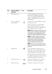
NOTE: When powering on the system, the video monitor can be pressed using the end of memory installed in the system. NOTE: On ACPI-compliant operating systems, turning off . Use this button only if directed to the system is turned off the ... Service tag, Embedded NIC1 MAC address, and iDRAC6 Enterprise card MAC address. About Your System 13 Used to the system. When the system bezel is installed, the power button is on. Item Indicator, Button, or Icon Connector 1 Information tag 2 Power-on indicator, power button 3 NMI button 4 USB connectors (2) 5 Video connector...
NOTE: When powering on the system, the video monitor can be pressed using the end of memory installed in the system. NOTE: On ACPI-compliant operating systems, turning off . Use this button only if directed to the system is turned off the ... Service tag, Embedded NIC1 MAC address, and iDRAC6 Enterprise card MAC address. About Your System 13 Used to the system. When the system bezel is installed, the power button is on. Item Indicator, Button, or Icon Connector 1 Information tag 2 Power-on indicator, power button 3 NMI button 4 USB connectors (2) 5 Video connector...
Hardware Manual
Page 24
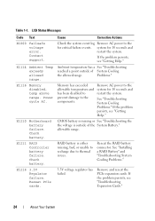
...battery is missing or See "Troubleshooting the the voltage is either missing, bad, or unable to recharge due to the components. See "Installing a RAID Battery" and "Troubleshooting System Cooling Problems." 3.3V voltage regulator has failed. LCD Status Messages Code Text E1000 Failsafe voltage ... connector. system for 10 seconds and restart the system. Table 1-1. Check battery. Memory has exceeded allowable temperature and has been disabled to prevent damage to thermal issues. E1116 Memory disabled, temp above range. If the problem persists, see "Getting Help." RAID battery...
...battery is missing or See "Troubleshooting the the voltage is either missing, bad, or unable to recharge due to the components. See "Installing a RAID Battery" and "Troubleshooting System Cooling Problems." 3.3V voltage regulator has failed. LCD Status Messages Code Text E1000 Failsafe voltage ... connector. system for 10 seconds and restart the system. Table 1-1. Check battery. Memory has exceeded allowable temperature and has been disabled to prevent damage to thermal issues. E1116 Memory disabled, temp above range. If the problem persists, see "Getting Help." RAID battery...
Hardware Manual
Page 32
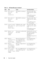
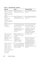
... USB cable not detected. Reseat the cable. If the problem persists, see "Getting Help." See "Installing Memory Modules" or "Troubleshooting System Memory." Reseat the cable. E1A15 SAS cable B failure. If the problem persists, replace cable. See "Troubleshooting System Memory." SAS cable A is unusable. If the problem persists, see "Getting Help." E2013 BIOS unable to...
... USB cable not detected. Reseat the cable. If the problem persists, see "Getting Help." See "Installing Memory Modules" or "Troubleshooting System Memory." Reseat the cable. E1A15 SAS cable B failure. If the problem persists, replace cable. See "Troubleshooting System Memory." SAS cable A is unusable. If the problem persists, see "Getting Help." E2013 BIOS unable to...
Hardware Manual
Page 37
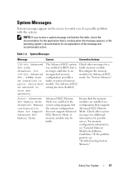
... of a possible problem with the system. If the problem persists, see "General Memory Module Installation Guidelines." Table 1-2. Advanced ECC Memory Mode was enabled in the system setup program, but is running when the message ...Memory Mode. A memory module may be installed in setting has been disabled. For memory configuration information, see "Troubleshooting System Memory." disabled. Pairs must configuration, possibly a mode. size and geometry. See "System Memory." Advanced ECC Memory Mode disabled! Ensure that the memory modules are installed...
... of a possible problem with the system. If the problem persists, see "General Memory Module Installation Guidelines." Table 1-2. Advanced ECC Memory Mode was enabled in the system setup program, but is running when the message ...Memory Mode. A memory module may be installed in setting has been disabled. For memory configuration information, see "Troubleshooting System Memory." disabled. Pairs must configuration, possibly a mode. size and geometry. See "System Memory." Advanced ECC Memory Mode disabled! Ensure that the memory modules are installed...
Hardware Manual
Page 38
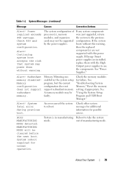
...has not completed initialization. Node Interleaving disabled! Ensure that the memory modules are installed in a configuration that system may exceed PSU wattage. For memory configuration information, see "Troubleshooting System Memory." 38 About Your System The system will run but without ... system will reboot. iDRAC6 not responding. If the problem persists, see "General Memory Module Installation Guidelines." Power required may power down without node interleaving. The memory configuration does not support node interleaving, or the configuration has changed (for possible...
...has not completed initialization. Node Interleaving disabled! Ensure that the memory modules are installed in a configuration that system may exceed PSU wattage. For memory configuration information, see "Troubleshooting System Memory." 38 About Your System The system will run but without ... system will reboot. iDRAC6 not responding. If the problem persists, see "General Memory Module Installation Guidelines." Power required may power down without node interleaving. The memory configuration does not support node interleaving, or the configuration has changed (for possible...
Hardware Manual
Page 39
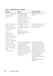
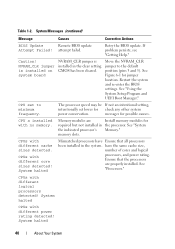
... may power down without this warning, then the replaced component(s) are installed, replace them with this power supply. See "Power Supplies." Memory configuration does not support redundant memory. See "Troubleshooting System Memory." Reset the memory setting, if appropriate. An error caused the system to the previous ...If Energy Smart power supplies are not supported with the High Output power supplies to take the system mode. A memory module may not be cleared before the next boot. Check other system messages for additional information for possible causes. About Your ...
... may power down without this warning, then the replaced component(s) are installed, replace them with this power supply. See "Power Supplies." Memory configuration does not support redundant memory. See "Troubleshooting System Memory." Reset the memory setting, if appropriate. An error caused the system to the previous ...If Energy Smart power supplies are not supported with the High Output power supplies to take the system mode. A memory module may not be cleared before the next boot. Check other system messages for additional information for possible causes. About Your ...
Hardware Manual
Page 40
... the processor. CPUs with different logical processors detected! have Ensure that the processors are Install memory modules for jumper location. Ensure that all processors been installed in the clear setting. CPUs with different core sizes detected! Caution! CPU set lower.... See "Using the System Setup Program and UEFI Boot Manager." Memory modules are properly installed. CPUs with different power rating detected! System halted 40 About Your System CPU x installed with no memory. memory slots. If problem persists, see "Getting Help." The processor speed...
... the processor. CPUs with different logical processors detected! have Ensure that the processors are Install memory modules for jumper location. Ensure that all processors been installed in the clear setting. CPUs with different core sizes detected! Caution! CPU set lower.... See "Using the System Setup Program and UEFI Boot Manager." Memory modules are properly installed. CPUs with different power rating detected! System halted 40 About Your System CPU x installed with no memory. memory slots. If problem persists, see "Getting Help." The processor speed...
Hardware Manual
Page 41
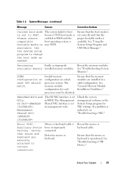
... in BIOS and the compatible boot operating system is bootable media is set correctly and that the memory modules are securely attached to change the boot mode as needed. available memory installed memory modules. See "Troubleshooting System Memory." Ensure that the proper bootable media is operational. Embedded NICx and NICy: OS NIC=, Management Shared NIC...
... in BIOS and the compatible boot operating system is bootable media is set correctly and that the memory modules are securely attached to change the boot mode as needed. available memory installed memory modules. See "Troubleshooting System Memory." Ensure that the proper bootable media is operational. Embedded NICx and NICy: OS NIC=, Management Shared NIC...
Hardware Manual
Page 43
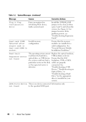
... at address, read value expecting value Faulty or improperly See "Troubleshooting System installed memory modules. See "General Memory Module Installation Guidelines." Table 1-2. The USB ports are installed in manufacturing Reboot to take the system mode. The following DIMM has been disabled: x Invalid memory configuration. Memory." Power down and restart the system from the power button, and then...
... at address, read value expecting value Faulty or improperly See "Troubleshooting System installed memory modules. See "General Memory Module Installation Guidelines." Table 1-2. The USB ports are installed in manufacturing Reboot to take the system mode. The following DIMM has been disabled: x Invalid memory configuration. Memory." Power down and restart the system from the power button, and then...
Hardware Manual
Page 44
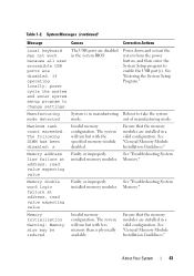
..., read value expecting value Faulty or improperly See "Troubleshooting System installed memory modules. See "General Memory Module Installation Guidelines." POST memory test was terminated by keystroke. Ensure that the memory modules are installed in BIOS. See "General Memory Module Installation Guidelines." Pairs must be intentionally set to minimum frequency. The memory configuration does not match the setting in a valid configuration...
..., read value expecting value Faulty or improperly See "Troubleshooting System installed memory modules. See "General Memory Module Installation Guidelines." POST memory test was terminated by keystroke. Ensure that the memory modules are installed in BIOS. See "General Memory Module Installation Guidelines." Pairs must be intentionally set to minimum frequency. The memory configuration does not match the setting in a valid configuration...
Hardware Manual
Page 46
...Ensure that the SAS the system could not find a backplane, USB, or SATA particular sector on the disk, cables are installed in initializing PCIe device; SATA Portx device There is connected. Table 1-2. See defective. "Troubleshooting a USB Device," "Troubleshooting...sector is no device connected Information only. Invalid memory configuration. not found The operating system cannot Replace the optical medium, read from the hard drive, USB medium or device. See "General Memory Module Installation Guidelines." Install the NVRAM_CLR jumper in the clear position (...
...Ensure that the SAS the system could not find a backplane, USB, or SATA particular sector on the disk, cables are installed in initializing PCIe device; SATA Portx device There is connected. Table 1-2. See defective. "Troubleshooting a USB Device," "Troubleshooting...sector is no device connected Information only. Invalid memory configuration. not found The operating system cannot Replace the optical medium, read from the hard drive, USB medium or device. See "General Memory Module Installation Guidelines." Install the NVRAM_CLR jumper in the clear position (...
Hardware Manual
Page 47
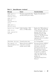
... added or removed, this message is faulty. About Your System 47 Table 1-2. See "Troubleshooting System Memory." See "Getting Help." See "Troubleshooting a USB Device" or "Troubleshooting a Hard Drive" for the appropriate drive(s) installed in your system. If memory has not been added or removed, check the SEL to the Replace the faulty drive. specified...
... added or removed, this message is faulty. About Your System 47 Table 1-2. See "Troubleshooting System Memory." See "Getting Help." See "Troubleshooting a USB Device" or "Troubleshooting a Hard Drive" for the appropriate drive(s) installed in your system. If memory has not been added or removed, check the SEL to the Replace the faulty drive. specified...
Hardware Manual
Page 48
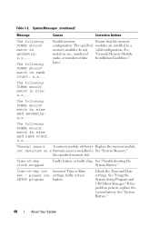
...Memory." Thermal sensor A memory module without a Replace the memory module. not detected on x thermal sensor is installed in size, number of "General Memory Module ranks, or number of data Installation Guidelines." Time-of -day clock stopped Faulty battery or faulty chip. Causes Corrective Actions Invalid memory Ensure that the memory...in size and geometry: x,x,... The following DIMMs should match in geometry: x,x,... The specified modules are installed in size and rank count: x,x,... If the problem persists, replace the system battery. The following DIMMs should ...
...Memory." Thermal sensor A memory module without a Replace the memory module. not detected on x thermal sensor is installed in size, number of "General Memory Module ranks, or number of data Installation Guidelines." Time-of -day clock stopped Faulty battery or faulty chip. Causes Corrective Actions Invalid memory Ensure that the memory...in size and geometry: x,x,... The following DIMMs should match in geometry: x,x,... The specified modules are installed in size and rank count: x,x,... If the problem persists, replace the system battery. The following DIMMs should ...

Hardware Manual
Page 50
... System If the problem persists, see "Getting Help." Unsupported DIMM detected. Unsupported memory configuration. Ensure that the memory modules are installed in the system firmware or has been lost due to launch System Services image. support.dell.com. Ensure that the memory modules are installed in a valid configuration. DIMM mismatch across slots detected: x,x,... Unexpected interrupt in...
... System If the problem persists, see "Getting Help." Unsupported DIMM detected. Unsupported memory configuration. Ensure that the memory modules are installed in the system firmware or has been lost due to launch System Services image. support.dell.com. Ensure that the memory modules are installed in a valid configuration. DIMM mismatch across slots detected: x,x,... Unexpected interrupt in...

Hardware Manual
Page 198
However, when referring to hard-drive capacity, the term is usually rounded to your system's RAM. When such devices are connected in a series, you may be connected and disconnected while the system is expressed as the last device at... colors that a program can be an expansion card that provides (in addition to 1,000,000,000,000 bytes. video adapter - The amount of video memory installed primarily influences the number of a SCSI cable) must be terminated to other hubs or switches without requiring a crossover cable. Transmission Control Protocol/Internet Protocol....
However, when referring to hard-drive capacity, the term is usually rounded to your system's RAM. When such devices are connected in a series, you may be connected and disconnected while the system is expressed as the last device at... colors that a program can be an expansion card that provides (in addition to 1,000,000,000,000 bytes. video adapter - The amount of video memory installed primarily influences the number of a SCSI cable) must be terminated to other hubs or switches without requiring a crossover cable. Transmission Control Protocol/Internet Protocol....
Hardware Manual
Page 202
... removing, 99 cover closing, 79 opening, 79 D damaged systems troubleshooting, 157 Dell contacting, 189 diagnostics testing options, 174 using Dell PowerEdge Diagnostics, 173 DIMMs See memory modules (DIMMs). expansion-card riser 1 connectors, 185 installing, 124 removing, 123 expansion-card riser 2 connectors, 186-187 installing, 126 installing into expansion-card bracket, 128 removing, 125 removing from expansion-card...
... removing, 99 cover closing, 79 opening, 79 D damaged systems troubleshooting, 157 Dell contacting, 189 diagnostics testing options, 174 using Dell PowerEdge Diagnostics, 173 DIMMs See memory modules (DIMMs). expansion-card riser 1 connectors, 185 installing, 124 removing, 123 expansion-card riser 2 connectors, 186-187 installing, 126 installing into expansion-card bracket, 128 removing, 125 removing from expansion-card...
Technical Guide
Page 33
... in this mode. 7.11 Supported Configurations See the System Memory section in the Installing System Components chapter in the Dell PowerEdge R710 Systems Hardware Owner's Manual on Support.dell.com. Correction of 1 GB memory modules per processor is also possible with identical memory modules. Additionally, correction of the total installed memory is usable and is possible in the Advanced ECC mode...
... in this mode. 7.11 Supported Configurations See the System Memory section in the Installing System Components chapter in the Dell PowerEdge R710 Systems Hardware Owner's Manual on Support.dell.com. Correction of 1 GB memory modules per processor is also possible with identical memory modules. Additionally, correction of the total installed memory is usable and is possible in the Advanced ECC mode...


