
Hardware Manual
Page 14
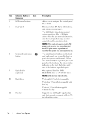
... is pushed again. The identification buttons on chassis with flex bay Up to AC power and an error has been detected, the LCD lights amber regardless of the buttons is pushed, the LCD panel on the front and the system status indicator on the back flash blue until one of...) 14 About Your System One optional slim-line SATA DVD-ROM drive or DVD+RW drive. NOTE: DVD devices are data only. Provides system ID, status information, and system error messages. The LCD lights amber when the system needs attention, and the LCD panel displays an error code followed by descriptive text. ...
... is pushed again. The identification buttons on chassis with flex bay Up to AC power and an error has been detected, the LCD lights amber regardless of the buttons is pushed, the LCD panel on the front and the system status indicator on the back flash blue until one of...) 14 About Your System One optional slim-line SATA DVD-ROM drive or DVD+RW drive. NOTE: DVD devices are data only. Provides system ID, status information, and system error messages. The LCD lights amber when the system needs attention, and the LCD panel displays an error code followed by descriptive text. ...
Hardware Manual
Page 18
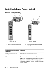
Drives are initialized after system power is applied. Hard-Drive Indicators 1 2 1 2 3.5-in carrier 1 drive-activity indicator (green) 2.5-in carrier 2 drive-status indicator (green and amber) Drive-Status Indicator Pattern (RAID Only) Blinks green two times per second Off Condition Identify drive/preparing for removal Drive ready for insertion or removal NOTE: The drive status indicator remains off until all hard drives are not ready for RAID Figure 1-4. Hard-Drive Indicator Patterns for insertion or removal during this time. 18 About Your System
Drives are initialized after system power is applied. Hard-Drive Indicators 1 2 1 2 3.5-in carrier 1 drive-activity indicator (green) 2.5-in carrier 2 drive-status indicator (green and amber) Drive-Status Indicator Pattern (RAID Only) Blinks green two times per second Off Condition Identify drive/preparing for removal Drive ready for insertion or removal NOTE: The drive status indicator remains off until all hard drives are not ready for RAID Figure 1-4. Hard-Drive Indicator Patterns for insertion or removal during this time. 18 About Your System
Hardware Manual
Page 19
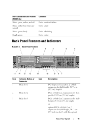
... Pattern (RAID Only) Blinks green, amber, and off Blinks amber four times per second Blinks green slowly Steady green Condition Drive predicted failure Drive failed Drive rebuilding Drive online Back Panel Features and Indicators Figure 1-5. Back Panel Features 1 2 3 4 5 6 15 14 13 12 11 Item Indicator, Button, or Icon Connector 1 PCIe slot 1 2 PCIe slot 2 3 ...
... Pattern (RAID Only) Blinks green, amber, and off Blinks amber four times per second Blinks green slowly Steady green Condition Drive predicted failure Drive failed Drive rebuilding Drive online Back Panel Features and Indicators Figure 1-5. Back Panel Features 1 2 3 4 5 6 15 14 13 12 11 Item Indicator, Button, or Icon Connector 1 PCIe slot 1 2 PCIe slot 2 3 ...
Technical Guide
Page 16
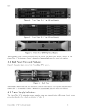
... view of the PowerEdge R710 Hardware Owner's Manual on Support.Dell.com for more information. 4.5 Power Supply Indicators The PowerEdge R710 redundant power supplies have one status bi-color LED: green for AC power present and amber for a fault as detailed in the About Your System chapter of the PowerEdge R710 server. Front View (3.5" Hard Drive Chassis) Figure 3. Front...
... view of the PowerEdge R710 Hardware Owner's Manual on Support.Dell.com for more information. 4.5 Power Supply Indicators The PowerEdge R710 redundant power supplies have one status bi-color LED: green for AC power present and amber for a fault as detailed in the About Your System chapter of the PowerEdge R710 server. Front View (3.5" Hard Drive Chassis) Figure 3. Front...
Technical Guide
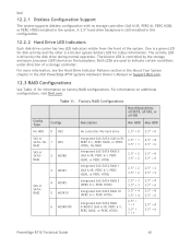
Page 42
...Drive Indicator Patterns section in the About Your System chapter in the Dell PowerEdge R710 Systems Hardware Owner's Manual on factory RAID configurations. The bicolor LED is a bicolor (green/amber) LED for information on Support.Dell...8214; = 6 2.5‖ = 2 3.5‖ = 2 2.5‖ = 8 3.5‖ = 6 2.5‖ = 8 3.5‖ = 6 2.5‖ = 8 3.5‖ = 6 PowerEdge R710 Technical Guide 42 One is a green LED for disk activity and the other is controlled by the disk drive during normal operation. Both LEDs are used to indicate certain conditions under direction of the system...
...Drive Indicator Patterns section in the About Your System chapter in the Dell PowerEdge R710 Systems Hardware Owner's Manual on factory RAID configurations. The bicolor LED is a bicolor (green/amber) LED for information on Support.Dell...8214; = 6 2.5‖ = 2 3.5‖ = 2 2.5‖ = 8 3.5‖ = 6 2.5‖ = 8 3.5‖ = 6 2.5‖ = 8 3.5‖ = 6 PowerEdge R710 Technical Guide 42 One is a green LED for disk activity and the other is controlled by the disk drive during normal operation. Both LEDs are used to indicate certain conditions under direction of the system...


