
Information Update - Intel Xeon 5600 Series Processors
Page 2
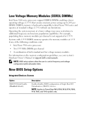
... voltage (1.35 V) that ensures memory power savings up to PowerEdge R410, R510, R610, R710, R910, T410, T610, and T710 systems only. Systems with 1.35 V DDR3L memory operates the memory modules at 1.5 V if any limitations. DDR3L memory is not supported at standard voltage...configuration of both standard and low voltage memory modules For information on the memory configuration guidelines, see your system's Hardware Owner's Manual at a lower voltage may cause restrictions to control frequency and voltage configuration within allowable limits. Operating the system memory at support.dell...
... voltage (1.35 V) that ensures memory power savings up to PowerEdge R410, R510, R610, R710, R910, T410, T610, and T710 systems only. Systems with 1.35 V DDR3L memory operates the memory modules at 1.5 V if any limitations. DDR3L memory is not supported at standard voltage...configuration of both standard and low voltage memory modules For information on the memory configuration guidelines, see your system's Hardware Owner's Manual at a lower voltage may cause restrictions to control frequency and voltage configuration within allowable limits. Operating the system memory at support.dell...
Information Update - Intel Xeon 5600 Series Processors
Page 3
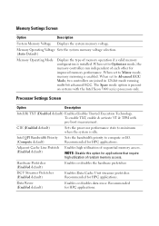
...Enabled default) Enables or disables data reuse. NOTE: Disable this option for applications that require high utilization of sequential memory access. To enable TXT, enable & activate VT & TPM with the Intel Xeon 5600 series processors only. Adjacent...Recommended for improved memory performance. When set to Optimizer mode, the memory controllers run independent of memory operation if a valid memory configuration is present on systems with pre-boot measurement. Memory Operating Voltage Sets the system memory voltage selection. (Auto Default) Memory Operating Mode ...
...Enabled default) Enables or disables data reuse. NOTE: Disable this option for applications that require high utilization of sequential memory access. To enable TXT, enable & activate VT & TPM with the Intel Xeon 5600 series processors only. Adjacent...Recommended for improved memory performance. When set to Optimizer mode, the memory controllers run independent of memory operation if a valid memory configuration is present on systems with pre-boot measurement. Memory Operating Voltage Sets the system memory voltage selection. (Auto Default) Memory Operating Mode ...
Hardware Owner's Manual
Page 33
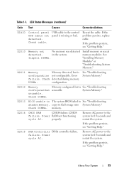
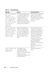
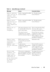
... E1A1D Control panel USB cable not detected. See "Installing Memory Modules" or "Troubleshooting System Memory." Error failure. E2012 Memory Memory configured, but is See "Troubleshooting configured but is missing or bad. System Memory." Check DIMMs. memory. CMOS failure. Power RAM not functioning cycle AC. Remove...Help." Check DIMMs. E2013 BIOS unable to The system BIOS failed to the control panel is configuration not configurable. copy its flash image into System Memory." Remove AC power to the system for 10 seconds and restart the system. USB cable ...
... E1A1D Control panel USB cable not detected. See "Installing Memory Modules" or "Troubleshooting System Memory." Error failure. E2012 Memory Memory configured, but is See "Troubleshooting configured but is missing or bad. System Memory." Check DIMMs. memory. CMOS failure. Power RAM not functioning cycle AC. Remove...Help." Check DIMMs. E2013 BIOS unable to The system BIOS failed to the control panel is configuration not configurable. copy its flash image into System Memory." Remove AC power to the system for 10 seconds and restart the system. USB cable ...
Hardware Owner's Manual
Page 35
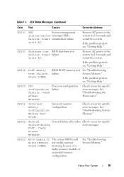
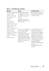
... Power initialization failure. E201D Shutdown test BIOS shutdown test failure. Table 1-1. Power failure. E201E POST memory test failure. See "Troubleshooting System Memory." Remove AC power to the system for specific failure during error messages. E2021 Incorrect Incorrect memory memory configuration. See "Troubleshooting System Memory." cycle AC. If the problem persists, see "Getting Help." See "Troubleshooting System...
... Power initialization failure. E201D Shutdown test BIOS shutdown test failure. Table 1-1. Power failure. E201E POST memory test failure. See "Troubleshooting System Memory." Remove AC power to the system for specific failure during error messages. E2021 Incorrect Incorrect memory memory configuration. See "Troubleshooting System Memory." cycle AC. If the problem persists, see "Getting Help." See "Troubleshooting System...
Hardware Owner's Manual
Page 38
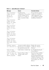
... Advanced ECC option Check other system messages for additional information for Advanced ECC configuration, possibly a mode. Memory configuration does not support Advanced ECC Memory Mode. Ensure that the memory modules are installed in BIOS, but the current configuration does not support Advanced ECC Memory Mode. The system will reboot. 38 About Your System See "System faulty or...
... Advanced ECC option Check other system messages for additional information for Advanced ECC configuration, possibly a mode. Memory configuration does not support Advanced ECC Memory Mode. Ensure that the memory modules are installed in BIOS, but the current configuration does not support Advanced ECC Memory Mode. The system will reboot. 38 About Your System See "System faulty or...
Hardware Owner's Manual
Page 39
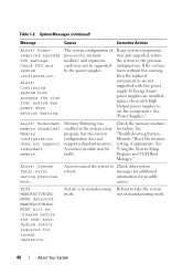
... The system will still run, but without warning. For memory configuration information, see "Troubleshooting System Memory." About Your System 39 Alert! Remove AC power to boot. The memory configuration does not support node interleaving, or the configuration has changed (for possible causes. responding. After AC recovery...the system. Continuing system boot The iDRAC6 was remotely reset while system was booting. Memory configuration does not support Node Interleaving. Node Interleaving disabled! Check other system messages for additional information for example...
... The system will still run, but without warning. For memory configuration information, see "Troubleshooting System Memory." About Your System 39 Alert! Remove AC power to boot. The memory configuration does not support node interleaving, or the configuration has changed (for possible causes. responding. After AC recovery...the system. Continuing system boot The iDRAC6 was remotely reset while system was booting. Memory configuration does not support Node Interleaving. Node Interleaving disabled! Check other system messages for additional information for example...
Hardware Owner's Manual
Page 40
... are not supported with High Output power supplies to take the system mode. Memory configuration does not support redundant memory. messages for additional information for normal operation. Redundant memory disabled! Reset the memory setting, if appropriate. MANUFACTURING MODE will be faulty. Alert! A memory module may be cleared before the next boot. Alert! An error caused the...
... are not supported with High Output power supplies to take the system mode. Memory configuration does not support redundant memory. messages for additional information for normal operation. Redundant memory disabled! Reset the memory setting, if appropriate. MANUFACTURING MODE will be faulty. Alert! A memory module may be cleared before the next boot. Alert! An error caused the...
Hardware Owner's Manual
Page 42
... is set to correct connectors. Verify that the enabled in BIOS. If a problem is operational. NIC= Error 8602 Auxiliary Device Failure. available memory memory modules. DIMM configuration on a dualprocessor system. Invalid memory configuration on each processor must be identical. Use the system setup program to boot Ensure that the boot mode is because UEFI boot...
... is set to correct connectors. Verify that the enabled in BIOS. If a problem is operational. NIC= Error 8602 Auxiliary Device Failure. available memory memory modules. DIMM configuration on a dualprocessor system. Invalid memory configuration on each processor must be identical. Use the system setup program to boot Ensure that the boot mode is because UEFI boot...

Hardware Owner's Manual
Page 44
... button, and then enter the System Setup program to change settings. out of manufacturing mode. The following DIMM has been disabled: x Invalid memory configuration. Ensure that the memory configuration. Memory Initialization Warning: Memory size may not work because all user accessible USB ports are installed in the system BIOS. See than is in a will run but...
... button, and then enter the System Setup program to change settings. out of manufacturing mode. The following DIMM has been disabled: x Invalid memory configuration. Ensure that the memory configuration. Memory Initialization Warning: Memory size may not work because all user accessible USB ports are installed in the system BIOS. See than is in a will run but...
Hardware Owner's Manual
Page 45
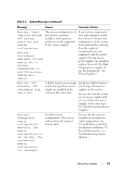
... failure at address, read value expecting value Faulty or improperly installed See "Troubleshooting memory modules. The memory frequency may support configuration supports the only the minimum frequency. MEMTEST lane failure detected on x Invalid memory configuration. Pairs must be matched in a valid configuration. Table 1-2. Memory set lower for check any other system power conservation. Information only. Mirror mode...
... failure at address, read value expecting value Faulty or improperly installed See "Troubleshooting memory modules. The memory frequency may support configuration supports the only the minimum frequency. MEMTEST lane failure detected on x Invalid memory configuration. Pairs must be matched in a valid configuration. Table 1-2. Memory set lower for check any other system power conservation. Information only. Mirror mode...
Hardware Owner's Manual
Page 49
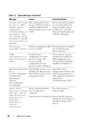
... stopped Faulty battery or faulty chip. See "Using the System Setup Program and UEFI Boot Manager." Invalid memory configuration. The following DIMMs should match in geometry: x,x,... Ensure that the memory modules are installed in size: x,x,... See "General Memory Module Installation Guidelines." faulty system SETUP program battery. System Messages (continued) Message Causes Corrective Actions The...
... stopped Faulty battery or faulty chip. See "Using the System Setup Program and UEFI Boot Manager." Invalid memory configuration. The following DIMMs should match in geometry: x,x,... Ensure that the memory modules are installed in size: x,x,... See "General Memory Module Installation Guidelines." faulty system SETUP program battery. System Messages (continued) Message Causes Corrective Actions The...

Hardware Owner's Manual
Page 51
...." or processor combination. Unified Server The iDRAC6 Enterprise card Configuration user flash memory may be documentation for instructions on support.dell.com. information. The following DIMM has been disabled: x Invalid memory configuration. System halted! See the to launch System Services image. Unexpected interrupt in a valid configuration. System halted after F10 Restart the system and keystroke because...
...." or processor combination. Unified Server The iDRAC6 Enterprise card Configuration user flash memory may be documentation for instructions on support.dell.com. information. The following DIMM has been disabled: x Invalid memory configuration. System halted! See the to launch System Services image. Unexpected interrupt in a valid configuration. System halted after F10 Restart the system and keystroke because...
Hardware Owner's Manual
Page 52
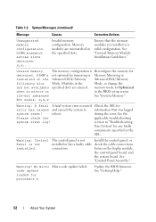
...BIOS setup screen. 128-bit advanced See "System Memory." See "Control Panel Assembly." See "Getting Help." 52 About Your System System Messages (continued) Message Causes Corrective Actions Unsupported memory configuration. The control panel is not installed. Warning! Table...and the system board. Ensure that was logged system reset! Unused memory The memory configuration is Reconfigure the memory for processor n Update the BIOS firmware. during the error. Invalid memory configuration. code update loaded for detected. Modules in the specified slots. section...
...BIOS setup screen. 128-bit advanced See "System Memory." See "Control Panel Assembly." See "Getting Help." 52 About Your System System Messages (continued) Message Causes Corrective Actions Unsupported memory configuration. The control panel is not installed. Warning! Table...and the system board. Ensure that was logged system reset! Unused memory The memory configuration is Reconfigure the memory for processor n Update the BIOS firmware. during the error. Invalid memory configuration. code update loaded for detected. Modules in the specified slots. section...
Hardware Owner's Manual
Page 53
...meet PSU wattage. system at the same time. Warning! The memory configuration is : Invalid memory configuration. Ensure that the memory modules are not supported with this power supply. PSU redundancy lost. Unsupported memory configuration detected. Table 1-2. Warning! Performance degraded. Warning! You can... with the High Output power supplies to use the components. The recommended memory configuration is not optimal. CPU and memory set to minimum frequencies to the previous configuration. If the system boots without this warning, then the replaced component(s) ...
...meet PSU wattage. system at the same time. Warning! The memory configuration is : Invalid memory configuration. Ensure that the memory modules are not supported with this power supply. PSU redundancy lost. Unsupported memory configuration detected. Table 1-2. Warning! Performance degraded. Warning! You can... with the High Output power supplies to use the components. The recommended memory configuration is not optimal. CPU and memory set to minimum frequencies to the previous configuration. If the system boots without this warning, then the replaced component(s) ...
Hardware Owner's Manual
Page 61
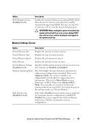
... POST. System Memory Speed Displays the system memory speed. For information about the memory modes, see "System Memory." System Memory Testing Specifies whether system memory tests are Enabled and Disabled. CAUTION: When setting this field is Enabled, memory interleaving is supported if a symmetric memory configuration is installed. System Memory Type Displays the type of memory operation if a valid memory configuration is enabled. Options...
... POST. System Memory Speed Displays the system memory speed. For information about the memory modes, see "System Memory." System Memory Testing Specifies whether system memory tests are Enabled and Disabled. CAUTION: When setting this field is Enabled, memory interleaving is supported if a symmetric memory configuration is installed. System Memory Type Displays the type of memory operation if a valid memory configuration is enabled. Options...
Hardware Owner's Manual
Page 124
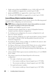
... producing any video output. • RDIMMs and UDIMMs cannot be mixed. • Except for memory channels that are unused, all populated memory channels must have identical configurations. • In a dual-processor configuration, the memory configuration for each channel depends on the memory configuration: - General Memory Module Installation Guidelines To ensure optimal performance of your system, observe the following order...
... producing any video output. • RDIMMs and UDIMMs cannot be mixed. • Except for memory channels that are unused, all populated memory channels must have identical configurations. • In a dual-processor configuration, the memory configuration for each channel depends on the memory configuration: - General Memory Module Installation Guidelines To ensure optimal performance of your system, observe the following order...
Hardware Owner's Manual
Page 125
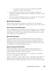
... supported in this mode. A minimal single-channel configuration of one 1-GB memory module per channel are mixed with x8-based memory modules. or dual-rank modules, the quad-rank modules must be installed in the farthest channel). The samples show sample memory configurations that follow the appropriate memory guidelines stated in this mode, all three channels...
... supported in this mode. A minimal single-channel configuration of one 1-GB memory module per channel are mixed with x8-based memory modules. or dual-rank modules, the quad-rank modules must be installed in the farthest channel). The samples show sample memory configurations that follow the appropriate memory guidelines stated in this mode, all three channels...
Hardware Owner's Manual
Page 126
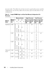
Sample RDIMM Single- memory totals. Table 3-2. and Dual-Rank Memory Configurations (Per Processor) Memory Mode Memory Sockets Memory Module 1 Size 4 2 5 3 6 Single Processor Dual Processor Physical Available Physical Available Memory Memory Memory Memory (GB) (GB) (GB) (GB) Optimizer 2-GB X 2 all 4 all X X 4 8 X X X 6 12 XX 4 8 XXXX 8 16 X X X X X X 12 24 4-GB X 4 all 8 all X... 32 64 126 Installing System Components The tables do not show mixed or quad-rank memory-module configurations, nor do they address the memory speed considerations of any...
Sample RDIMM Single- memory totals. Table 3-2. and Dual-Rank Memory Configurations (Per Processor) Memory Mode Memory Sockets Memory Module 1 Size 4 2 5 3 6 Single Processor Dual Processor Physical Available Physical Available Memory Memory Memory Memory (GB) (GB) (GB) (GB) Optimizer 2-GB X 2 all 4 all X X 4 8 X X X 6 12 XX 4 8 XXXX 8 16 X X X X X X 12 24 4-GB X 4 all 8 all X... 32 64 126 Installing System Components The tables do not show mixed or quad-rank memory-module configurations, nor do they address the memory speed considerations of any...
Hardware Owner's Manual
Page 127
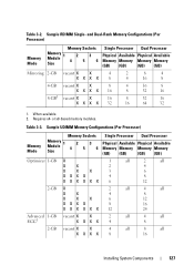
... X 4 8 2-GB vacant X X 4 X XX X 8 all 8 all 16 Installing System Components 127 Sample RDIMM Single- or x8-based memory modules. Table 3-2. and Dual-Rank Memory Configurations (Per Processor) Memory Mode Memory Sockets Memory Module 1 Size 4 2 5 3 6 Single Processor Dual Processor Physical Available Physical Available Memory Memory Memory Memory (GB) (GB) (GB) (GB) Mirroring 2-GB vacant X X 4 XXX X 8 2 8 4 4 16 8 4-GB vacant X X 8 4 16 8 X X X X 16 8 32 16...
... X 4 8 2-GB vacant X X 4 X XX X 8 all 8 all 16 Installing System Components 127 Sample RDIMM Single- or x8-based memory modules. Table 3-2. and Dual-Rank Memory Configurations (Per Processor) Memory Mode Memory Sockets Memory Module 1 Size 4 2 5 3 6 Single Processor Dual Processor Physical Available Physical Available Memory Memory Memory Memory (GB) (GB) (GB) (GB) Mirroring 2-GB vacant X X 4 XXX X 8 2 8 4 4 16 8 4-GB vacant X X 8 4 16 8 X X X X 16 8 32 16...
Hardware Owner's Manual
Page 128
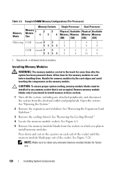
... has been powered down and out on the ejectors on the memory module. Remove memory-module blanks only if you intend to cool before handling them. Sample UDIMM Memory Configurations (Per Processor) Memory Mode Memory Sockets Memory Module 1 Size 4 2 5 3 6 Single Processor Dual Processor Physical Available Physical Available Memory Memory Memory Memory (GB) (GB) (GB) (GB) Mirroring 1-GB vacant X X 2 1 4 2 X XX X 4 2 8 4 2-GB vacant...
... has been powered down and out on the ejectors on the memory module. Remove memory-module blanks only if you intend to cool before handling them. Sample UDIMM Memory Configurations (Per Processor) Memory Mode Memory Sockets Memory Module 1 Size 4 2 5 3 6 Single Processor Dual Processor Physical Available Physical Available Memory Memory Memory Memory (GB) (GB) (GB) (GB) Mirroring 1-GB vacant X X 2 1 4 2 X XX X 4 2 8 4 2-GB vacant...


