
Hardware Owner's Manual
Page 3
Contents 1 About Your System 11 Accessing System Features During Startup 11 Front-Panel Features and Indicators 12 LCD Panel Features (Optional 14 Home Screen 16 Setup Menu 16 View Menu 17 Hard-Drive Status Indicators 18 Back-Panel Features and Indicators 19 Guidelines for Connecting External Devices 21 NIC Indicator Codes 21 Power Indicator Codes 22 Diagnostic Lights (Optional 23 LCD Status Messages (Optional 25 Solving Problems Described by LCD Status Messages (Optional 37 Removing LCD Status Messages (Optional 37 System Messages 38 Warning Messages 52 Contents 3
Contents 1 About Your System 11 Accessing System Features During Startup 11 Front-Panel Features and Indicators 12 LCD Panel Features (Optional 14 Home Screen 16 Setup Menu 16 View Menu 17 Hard-Drive Status Indicators 18 Back-Panel Features and Indicators 19 Guidelines for Connecting External Devices 21 NIC Indicator Codes 21 Power Indicator Codes 22 Diagnostic Lights (Optional 23 LCD Status Messages (Optional 25 Solving Problems Described by LCD Status Messages (Optional 37 Removing LCD Status Messages (Optional 37 System Messages 38 Warning Messages 52 Contents 3
Hardware Owner's Manual
Page 5
... the System 75 Front Bezel (Optional 77 Opening and Closing the System 78 Opening the System 78 Closing the System 79 Optical Drive (Optional 80 Removing an Optical Drive 80 Installing an Optical Drive 82 Hard Drives 83 Removing a Drive Blank 83 Installing a Drive Blank 84 Removing a Hard-Drive Carrier 84 Installing a Hard-Drive Carrier 86 Removing a Hard Drive From a Hard-Drive Carrier 86 Installing a Hard Drive Into a Hard-Drive Carrier 88 Contents 5
... the System 75 Front Bezel (Optional 77 Opening and Closing the System 78 Opening the System 78 Closing the System 79 Optical Drive (Optional 80 Removing an Optical Drive 80 Installing an Optical Drive 82 Hard Drives 83 Removing a Drive Blank 83 Installing a Drive Blank 84 Removing a Hard-Drive Carrier 84 Installing a Hard-Drive Carrier 86 Removing a Hard Drive From a Hard-Drive Carrier 86 Installing a Hard Drive Into a Hard-Drive Carrier 88 Contents 5

Hardware Owner's Manual
Page 6
Removing a Cabled Hard Drive 88 Installing a Cabled Hard Drive 89 Removing a Hard Drive From a Hard-Drive Bracket 91 Installing a Hard Drive Into a Hard-Drive Bracket 91 Expansion Card 92 Expansion Card Installation Guidelines 92 Installing an Expansion Card 94 Removing an Expansion Card 96 Expansion-Card Riser 97 Removing an Expansion-Card Riser 97 Installing an Expansion-Card Riser 99 Internal USB Memory Key 99 Cooling Shroud...
Removing a Cabled Hard Drive 88 Installing a Cabled Hard Drive 89 Removing a Hard Drive From a Hard-Drive Bracket 91 Installing a Hard Drive Into a Hard-Drive Bracket 91 Expansion Card 92 Expansion Card Installation Guidelines 92 Installing an Expansion Card 94 Removing an Expansion Card 96 Expansion-Card Riser 97 Removing an Expansion-Card Riser 97 Installing an Expansion-Card Riser 99 Internal USB Memory Key 99 Cooling Shroud...

Hardware Owner's Manual
Page 18
..., amber, and off until all hard drives are not ready for insertion or removal NOTE: The drive status indicator remains off Drive predicted failure Blinks amber four times per second Identify drive/preparing for removal Off Drive ready for insertion or removal during this time. Hard-Drive Indicators 2 1 1 drive-status indicator (green and amber) 2 drive-activity indicator (green) Drive-Status Indicator Pattern (RAID Only...
..., amber, and off until all hard drives are not ready for insertion or removal NOTE: The drive status indicator remains off Drive predicted failure Blinks amber four times per second Identify drive/preparing for removal Off Drive ready for insertion or removal during this time. Hard-Drive Indicators 2 1 1 drive-status indicator (green and amber) 2 drive-activity indicator (green) Drive-Status Indicator Pattern (RAID Only...

Hardware Owner's Manual
Page 32
...E2010 Memory not No memory was detected detected. Error detected during memory configuration. See "Troubleshooting a Hard Drive" on page 169. E1812 Hard drive ## The specified hard removed. E1A14 SAS cable A SAS cable A is missing or bad. Reseat the cable. connection. ...) Code Text Causes Corrective Actions E1810 Hard drive ## The specified hard drive fault. upgrade has failed. from the system. Reseat the cable. Check DIMMs. Memory detected, but is missing failure. Check drive has been removed drive. Reseat the cable. E1920 iDRAC6 Upgrade...
...E2010 Memory not No memory was detected detected. Error detected during memory configuration. See "Troubleshooting a Hard Drive" on page 169. E1812 Hard drive ## The specified hard removed. E1A14 SAS cable A SAS cable A is missing or bad. Reseat the cable. connection. ...) Code Text Causes Corrective Actions E1810 Hard drive ## The specified hard drive fault. upgrade has failed. from the system. Reseat the cable. Check DIMMs. Memory detected, but is missing failure. Check drive has been removed drive. Reseat the cable. E1920 iDRAC6 Upgrade...
Hardware Owner's Manual
Page 83
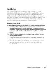
...your warranty. Read and follow the safety instructions that is not authorized by Dell is free of the system (see Figure 3-1). See "Front Bezel (Optional)" on page 77. 2 Grasp the front of the hard-drive blank, press the release lever on your product documentation, or as hot-...swappable. Installing System Components 83 CAUTION: To maintain proper system cooling, all empty hard-drive bays must have drive blanks installed. 1 If applicable, remove the front bezel. Depending on the right side, and slide the blank out until it is not covered by ...
...your warranty. Read and follow the safety instructions that is not authorized by Dell is free of the system (see Figure 3-1). See "Front Bezel (Optional)" on page 77. 2 Grasp the front of the hard-drive blank, press the release lever on your product documentation, or as hot-...swappable. Installing System Components 83 CAUTION: To maintain proper system cooling, all empty hard-drive bays must have drive blanks installed. 1 If applicable, remove the front bezel. Depending on the right side, and slide the blank out until it is not covered by ...
Hardware Owner's Manual
Page 84
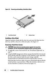
..., prepare the hard drive for removal. See your operating system supports hot-swap drive installation. When the hard-drive indicators are off, the hard drive is powered down. Figure 3-5. Removing a Hard-Drive Carrier CAUTION: Ensure that the drive can be removed safely. Wait until the release lever clicks into place. Removing and Installing a Hard-Drive Blank 1 2 1 hard-drive blank 2 release lever Installing a Drive Blank Align the hard-drive blank with the...
..., prepare the hard drive for removal. See your operating system supports hot-swap drive installation. When the hard-drive indicators are off, the hard drive is powered down. Figure 3-5. Removing a Hard-Drive Carrier CAUTION: Ensure that the drive can be removed safely. Wait until the release lever clicks into place. Removing and Installing a Hard-Drive Blank 1 2 1 hard-drive blank 2 release lever Installing a Drive Blank Align the hard-drive blank with the...
Hardware Owner's Manual
Page 85
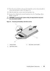
See Figure 3-6. 4 Slide the hard-drive carrier out of the hard-drive bay. 5 Insert a drive blank in the vacated hard-drive bay. Removing and Installing a Hard-Drive Carrier 1 2 1 release button 3 hard-drive carrier 3 2 hard-drive carrier handle Installing System Components 85 Figure 3-6. See "Installing a Drive Blank" on page 84. 3 Press the release button and open the hard-drive carrier release handle to release the hard-drive carrier. CAUTION: To maintain proper system cooling, all empty hard-drive bays must have drive blanks installed.
See Figure 3-6. 4 Slide the hard-drive carrier out of the hard-drive bay. 5 Insert a drive blank in the vacated hard-drive bay. Removing and Installing a Hard-Drive Carrier 1 2 1 release button 3 hard-drive carrier 3 2 hard-drive carrier handle Installing System Components 85 Figure 3-6. See "Installing a Drive Blank" on page 84. 3 Press the release button and open the hard-drive carrier release handle to release the hard-drive carrier. CAUTION: To maintain proper system cooling, all empty hard-drive bays must have drive blanks installed.
Hardware Owner's Manual
Page 86
... support team. See Figure 3-8. 5 Close the hard-drive carrier handle to lock the hard drive in the bay, remove it contacts the backplane. Removing a Hard Drive From a Hard-Drive Carrier CAUTION: Use only hard drives that the adjacent drives are fully installed. Remove the screws from the slide rails on the hard-drive carrier open, slide the hard-drive carrier into the hard-drive bay until it . CAUTION: Combining SATA...
... support team. See Figure 3-8. 5 Close the hard-drive carrier handle to lock the hard drive in the bay, remove it contacts the backplane. Removing a Hard Drive From a Hard-Drive Carrier CAUTION: Use only hard drives that the adjacent drives are fully installed. Remove the screws from the slide rails on the hard-drive carrier open, slide the hard-drive carrier into the hard-drive bay until it . CAUTION: Combining SATA...

Hardware Owner's Manual
Page 87
Figure 3-7. Installing and Removing a Hard Drive 1 2 4 1 screws (4) 3 SAS/SATA screw hole 3 2 hard drive 4 hard-drive carrier Installing System Components 87
Figure 3-7. Installing and Removing a Hard Drive 1 2 4 1 screws (4) 3 SAS/SATA screw hole 3 2 hard drive 4 hard-drive carrier Installing System Components 87
Hardware Owner's Manual
Page 88
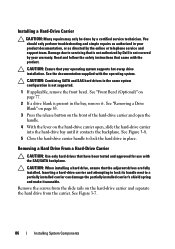
...Hard Drive Into a Hard-Drive Carrier NOTE: If you are upgrading from a 2.5" hard drive to a 3.5" hard drive, you need to remove the inserts inside the carrier before installing the 3.5" hard drive in the carrier. 1 Insert the hard drive into the hard-drive carrier with the connector end of the hard-drive carrier. 3 Attach the four screws to secure the hard drive... on the hard-drive carrier. Damage due to the hard-drive carrier. Read and follow the safety instructions that is not authorized by Dell is not covered by your product documentation, or as authorized in the hard-drive bay. 4 ...
...Hard Drive Into a Hard-Drive Carrier NOTE: If you are upgrading from a 2.5" hard drive to a 3.5" hard drive, you need to remove the inserts inside the carrier before installing the 3.5" hard drive in the carrier. 1 Insert the hard drive into the hard-drive carrier with the connector end of the hard-drive carrier. 3 Attach the four screws to secure the hard drive... on the hard-drive carrier. Damage due to the hard-drive carrier. Read and follow the safety instructions that is not authorized by Dell is not covered by your product documentation, or as authorized in the hard-drive bay. 4 ...
Hardware Owner's Manual
Page 89
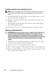
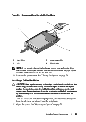
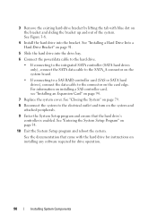
...not authorized by Dell is not covered by your product documentation, or as directed by a certified service technician. Installing System Components 89 Figure 3-8. See "Closing the System" on page 78. Installing a Cabled Hard Drive CAUTION: Many ...drive bracket (see "Removing a Hard Drive From a Hard-Drive Bracket" on page 91) and insert the empty bracket back into the drive bay. 5 Replace the system cover. Removing and Installing a Cabled Hard Drive 2 1 3 4 1 hard drive 3 tab 2 power/data cable 4 drive bracket NOTE: If you are not replacing the hard drive, remove the drive...
...not authorized by Dell is not covered by your product documentation, or as directed by a certified service technician. Installing System Components 89 Figure 3-8. See "Closing the System" on page 78. Installing a Cabled Hard Drive CAUTION: Many ...drive bracket (see "Removing a Hard Drive From a Hard-Drive Bracket" on page 91) and insert the empty bracket back into the drive bay. 5 Replace the system cover. Removing and Installing a Cabled Hard Drive 2 1 3 4 1 hard drive 3 tab 2 power/data cable 4 drive bracket NOTE: If you are not replacing the hard drive, remove the drive...
Hardware Owner's Manual
Page 90
... Setup program and reboot the system. See Figure 3-8. 4 Install the hard drive into the drive bay. 6 Connect the power/data cable to the hard drive. • If connecting to the integrated SATA controller (SATA hard drives only), connect the SATA data cable to the SATA_A connector on the..." on installing any software required for instructions on page 94. 7 Replace the system cover. 3 Remove the existing hard-drive bracket by lifting the tab with the hard drive for drive operation. 90 Installing System Components See "Entering the System Setup Program" on the bracket and sliding ...
... Setup program and reboot the system. See Figure 3-8. 4 Install the hard drive into the drive bay. 6 Connect the power/data cable to the hard drive. • If connecting to the integrated SATA controller (SATA hard drives only), connect the SATA data cable to the SATA_A connector on the..." on installing any software required for instructions on page 94. 7 Replace the system cover. 3 Remove the existing hard-drive bracket by lifting the tab with the hard drive for drive operation. 90 Installing System Components See "Entering the System Setup Program" on the bracket and sliding ...
Hardware Owner's Manual
Page 91
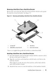
... the hard drives ordered from Dell. Figure 3-9. Installing a Hard Drive Into a Hard-Drive Bracket 1 Insert the hard drive into the hard-drive bracket with the back set of the drive at the back. See Figure 3-9. 2 Align the screw holes on the hard drive with the connector end of holes on the hard-drive bracket and separate the hard drive from the bracket. Installing System Components 91 Removing a Hard Drive From a Hard-Drive Bracket Remove...
... the hard drives ordered from Dell. Figure 3-9. Installing a Hard Drive Into a Hard-Drive Bracket 1 Insert the hard drive into the hard-drive bracket with the back set of the drive at the back. See Figure 3-9. 2 Align the screw holes on the hard drive with the connector end of holes on the hard-drive bracket and separate the hard drive from the bracket. Installing System Components 91 Removing a Hard Drive From a Hard-Drive Bracket Remove...
Hardware Owner's Manual
Page 103
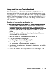
... expansion card. Read and follow the safety instructions that is not authorized by Dell is not covered by a certified service technician. Removing the Integrated Storage Controller Card CAUTION: Many repairs may only be done by your system's internal hard drives. Integrated Storage Controller Card Your system includes a dedicated expansion-card slot on the card...
... expansion card. Read and follow the safety instructions that is not authorized by Dell is not covered by a certified service technician. Removing the Integrated Storage Controller Card CAUTION: Many repairs may only be done by your system's internal hard drives. Integrated Storage Controller Card Your system includes a dedicated expansion-card slot on the card...

Hardware Owner's Manual
Page 128
... came with power-supply removal. See "Opening the System" on page 78. 5 Disconnect all attached peripherals. 2 Disconnect the power cable from the power source. 3 Disconnect the power cable from the power supply to the system board, hard drives and optical drive. Damage due to servicing that is not authorized by Dell is not covered by...
... came with power-supply removal. See "Opening the System" on page 78. 5 Disconnect all attached peripherals. 2 Disconnect the power cable from the power source. 3 Disconnect the power cable from the power supply to the system board, hard drives and optical drive. Damage due to servicing that is not authorized by Dell is not covered by...
Hardware Owner's Manual
Page 135
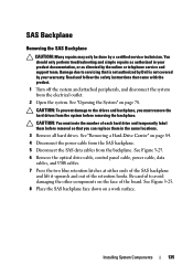
... authorized by Dell is not covered by a certified service technician. CAUTION: To prevent damage to the drives and backplane, you can replace them in your warranty. Installing System Components 135 CAUTION: You must remove the hard drives from the system before removal so that ...you must note the number of each hard drive and temporarily label them before removing the backplane. SAS Backplane Removing the SAS Backplane CAUTION: Many repairs may only...
... authorized by Dell is not covered by a certified service technician. CAUTION: To prevent damage to the drives and backplane, you can replace them in your warranty. Installing System Components 135 CAUTION: You must remove the hard drives from the system before removal so that ...you must note the number of each hard drive and temporarily label them before removing the backplane. SAS Backplane Removing the SAS Backplane CAUTION: Many repairs may only...

Hardware Owner's Manual
Page 137
...79. 6 Reconnect the system to its electrical outlet and turn the system on the system board. Damage due to servicing that is not authorized by Dell is not covered by your product documentation, or as directed by the online or telephone service and support team. Installing System Components 137 You should... only perform troubleshooting and simple repairs as authorized in their original locations. 5 Close the system. Installing the SAS Backplane CAUTION: Many repairs may have removed to uninstall the SAS backplane. 4 Install the hard drives in your warranty. See Figure 3-25.
...79. 6 Reconnect the system to its electrical outlet and turn the system on the system board. Damage due to servicing that is not authorized by Dell is not covered by your product documentation, or as directed by the online or telephone service and support team. Installing System Components 137 You should... only perform troubleshooting and simple repairs as authorized in their original locations. 5 Close the system. Installing the SAS Backplane CAUTION: Many repairs may have removed to uninstall the SAS backplane. 4 Install the hard drives in your warranty. See Figure 3-25.

Hardware Owner's Manual
Page 141
...must supply the recovery key when you restart your system or program before removing the system board. 6 Remove the system battery. Be sure to create a recovery key during operation. See "Removing a Processor" on your hard drives. 1 Turn off the system and attached peripherals, and disconnect the ...TPM) with the product. To avoid burns, ensure that is not authorized by Dell is not covered by your product documentation, or as directed by a certified service technician. See "Removing an iDRAC6 Enterprise Card" on page 111. You should only perform troubleshooting and...
...must supply the recovery key when you restart your system or program before removing the system board. 6 Remove the system battery. Be sure to create a recovery key during operation. See "Removing a Processor" on your hard drives. 1 Turn off the system and attached peripherals, and disconnect the ...TPM) with the product. To avoid burns, ensure that is not authorized by Dell is not covered by your product documentation, or as directed by a certified service technician. See "Removing an iDRAC6 Enterprise Card" on page 111. You should only perform troubleshooting and...

Hardware Owner's Manual
Page 148
...due to the same data transmission speed. • Use another connector on page 78. 3 Remove the following components from the electrical outlet. 2 Open the system. See "Installing System Components" ...bound. See "Integrated Devices Screen" on page 60. 6 Ensure that is not authorized by Dell is not covered by your product documentation, or as authorized in your warranty. Troubleshooting a Wet...cables are all set to servicing that the NICs, hubs, and switches on page 75. • Hard drives • USB memory key • NIC hardware key • VFlash media • Expansion card...
...due to the same data transmission speed. • Use another connector on page 78. 3 Remove the following components from the electrical outlet. 2 Open the system. See "Installing System Components" ...bound. See "Integrated Devices Screen" on page 60. 6 Ensure that is not authorized by Dell is not covered by your product documentation, or as authorized in your warranty. Troubleshooting a Wet...cables are all set to servicing that the NICs, hubs, and switches on page 75. • Hard drives • USB memory key • NIC hardware key • VFlash media • Expansion card...


