
Glossary
Page 1
... where the system is used to a system, usually by the DMTF. Dell™ Glossary NOTE: For additional information on storage terminology, visit the Storage... at www.snia.org and click on a regular basis. Alternating current. ACPI - Advanced Configuration and Power Interface. A module that includes power supplies and fans. CIM - bootable media ... the components of a program or data file. The modules are mounted into a chassis that contains a processor, memory, and a hard drive. A - ambient temperature - American National Standards Institute. asset tag - A copy of...
... where the system is used to a system, usually by the DMTF. Dell™ Glossary NOTE: For additional information on storage terminology, visit the Storage... at www.snia.org and click on a regular basis. Alternating current. ACPI - Advanced Configuration and Power Interface. A module that includes power supplies and fans. CIM - bootable media ... the components of a program or data file. The modules are mounted into a chassis that contains a processor, memory, and a hard drive. A - ambient temperature - American National Standards Institute. asset tag - A copy of...

Glossary
Page 2
..., for the serial ports on your system. See processor. A program that relieves the system's processor of a clock cycle. See also memory module. ERA - Embedded remote access. Electrostatic discharge. An add-in card, such as a NIC or SCSI adapter, that plugs into...tasks. A technology in -line memory module. device driver - controller - DC - DDR - Dynamic Host Configuration Protocol. DVD - ESM - coprocessor - A method of data between the processor and memory or between the expansion bus and a peripheral. 2 Dual in memory modules that controls the transfer of...
..., for the serial ports on your system. See processor. A program that relieves the system's processor of a clock cycle. See also memory module. ERA - Embedded remote access. Electrostatic discharge. An add-in card, such as a NIC or SCSI adapter, that plugs into...tasks. A technology in -line memory module. device driver - controller - DC - DDR - Dynamic Host Configuration Protocol. DVD - ESM - coprocessor - A method of data between the processor and memory or between the expansion bus and a peripheral. 2 Dual in memory modules that controls the transfer of...

Glossary
Page 6
...an NMI to a system. Memory that communicates with managed objects and accesses data and event notifications from a variety of sources. parity stripe - In RAID arrays, a striped hard drive containing parity data. A standard for maintaining the date, time, and system configuration information. Power distribution unit.... in a rack. A way of pixels up and down. Nanosecond(s). NVRAM is expressed as RAM and hard drives. PowerEdge RAID controller. Redundant information that controls the interpretation and execution of data. The primary computational chip inside the system that...
...an NMI to a system. Memory that communicates with managed objects and accesses data and event notifications from a variety of sources. parity stripe - In RAID arrays, a striped hard drive containing parity data. A standard for maintaining the date, time, and system configuration information. Power distribution unit.... in a rack. A way of pixels up and down. Nanosecond(s). NVRAM is expressed as RAM and hard drives. PowerEdge RAID controller. Redundant information that controls the interpretation and execution of data. The primary computational chip inside the system that...

Glossary
Page 8
... offload engine. U-DIMM - Universal Serial Bus. See memory key. 8 A standard interface that allows you to other hubs or switches without requiring a crossover cable. TCP/IP - uplink port - USB - SMP - system configuration information - system board - Simple Network Management Protocol. ...an electrical failure. TOE - Some devices (such as password protection. Super video graphics array. system memory - The amount of disks in the configuration software for multiple USB-compliant devices, such as the processor(s), RAM, controllers for video adapters with greater...
... offload engine. U-DIMM - Universal Serial Bus. See memory key. 8 A standard interface that allows you to other hubs or switches without requiring a crossover cable. TCP/IP - uplink port - USB - SMP - system configuration information - system board - Simple Network Management Protocol. ...an electrical failure. TOE - Some devices (such as password protection. Super video graphics array. system memory - The amount of disks in the configuration software for multiple USB-compliant devices, such as the processor(s), RAM, controllers for video adapters with greater...

Hardware Owner's Manual
Page 24
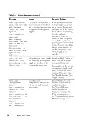
.../or system board hardware failure. Code Causes Hard drive failure. No memory modules detected. Memory" on page 146. Ensure that the diskette drive and hard drive are properly connected. Possible system resource configuration error. See "Troubleshooting Your System" on page 145 for information on...169. See "Getting Help" on page 153. Corrective Action Ensure that the optical drive and hard drives are properly connected. Memory configuration See "Troubleshooting System error. See "Getting Help" on page 169. Possible USB failure. See "Getting Help" on page 169...
.../or system board hardware failure. Code Causes Hard drive failure. No memory modules detected. Memory" on page 146. Ensure that the diskette drive and hard drive are properly connected. Possible system resource configuration error. See "Troubleshooting Your System" on page 145 for information on...169. See "Getting Help" on page 153. Corrective Action Ensure that the optical drive and hard drives are properly connected. Memory configuration See "Troubleshooting System error. See "Getting Help" on page 169. Possible USB failure. See "Getting Help" on page 169...

Hardware Owner's Manual
Page 32
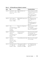
... Help" on page 158. E1A15 SAS cable B SAS cable B is not configurable. USB cable to the control panel is missing failure. Inspect DIMMs. Install memory or reseat memory modules. E2011 Memory configuration failure. See "Troubleshooting a Hard Drive" on page 169. E1812 Hard drive ... E1A1D Control panel USB cable not detected. Check or bad. If the problem persists, replace cable. Table 1-2. Error detected during memory configuration. in the system. E1A14 SAS cable A SAS cable A is missing or bad. LCD Status Messages (Optional) (continued) Code...
... Help" on page 158. E1A15 SAS cable B SAS cable B is not configurable. USB cable to the control panel is missing failure. Inspect DIMMs. Install memory or reseat memory modules. E2011 Memory configuration failure. See "Troubleshooting a Hard Drive" on page 169. E1812 Hard drive ... E1A1D Control panel USB cable not detected. Check or bad. If the problem persists, replace cable. Table 1-2. Error detected during memory configuration. in the system. E1A14 SAS cable A SAS cable A is missing or bad. LCD Status Messages (Optional) (continued) Code...

Hardware Owner's Manual
Page 33
copy its flash image into System Memory" on unusable. CMOS failure. properly. Power cycle AC. If the problem persists, see "Getting Help" on page 169. failure. If the problem persists, see "Getting ... controller failure. If the problem persists, see "Getting Help" on page 169. LCD Status Messages (Optional) (continued) Code Text Causes Corrective Actions E2012 Memory Memory configured, but is See "Troubleshooting configured but unusable. E2014 CMOS RAM CMOS failure. failure. Remove AC power to the system for 10 seconds and restart the system. Remove AC...
copy its flash image into System Memory" on unusable. CMOS failure. properly. Power cycle AC. If the problem persists, see "Getting Help" on page 169. failure. If the problem persists, see "Getting ... controller failure. If the problem persists, see "Getting Help" on page 169. LCD Status Messages (Optional) (continued) Code Text Causes Corrective Actions E2012 Memory Memory configured, but is See "Troubleshooting configured but unusable. E2014 CMOS RAM CMOS failure. failure. Remove AC power to the system for 10 seconds and restart the system. Remove AC...
Hardware Owner's Manual
Page 35
... and restart the system. See "Troubleshooting the Processor" on page 153. E2021 Incorrect memory Incorrect memory configuration. See "Troubleshooting System Memory" on page 160. multi-bit error (MBE). Remove AC power to the system for specific error messages. failure. E2020 CPU Processor configuration configuration failure. failure. Review User Guide. slot "##" has had a Reseat DIMM. Table 1-2. Power...
... and restart the system. See "Troubleshooting the Processor" on page 153. E2021 Incorrect memory Incorrect memory configuration. See "Troubleshooting System Memory" on page 160. multi-bit error (MBE). Remove AC power to the system for specific error messages. failure. E2020 CPU Processor configuration configuration failure. failure. Review User Guide. slot "##" has had a Reseat DIMM. Table 1-2. Power...

Hardware Owner's Manual
Page 42
...and enter system setup program to take the system mode. Memory Initialization Warning: Memory size may not work because all user accessible USB ports are installed in a will run but with less memory valid configuration. The system modules are disabled. Remove the PCIe expansion ... the Internal_Storage slot! The USB ports are installed in the dedicated storage controller slot. keyboard connector. Ensure that the memory configuration. Power down and restart the system from the power button, and then enter the System Setup program to enable the USB...
...and enter system setup program to take the system mode. Memory Initialization Warning: Memory size may not work because all user accessible USB ports are installed in a will run but with less memory valid configuration. The system modules are disabled. Remove the PCIe expansion ... the Internal_Storage slot! The USB ports are installed in the dedicated storage controller slot. keyboard connector. Ensure that the memory configuration. Power down and restart the system from the power button, and then enter the System Setup program to enable the USB...

Hardware Owner's Manual
Page 43
... available. See "Using the System Setup Program and UEFI Boot Manager" on setting the order of boot devices. Table 1-3. The memory frequency may support configuration supports the only the minimum frequency. See "General Memory Module Installation Guidelines" on x. Ensure that your memory configuration may If not an intentional setting, be intentionally set to minimum frequency...
... available. See "Using the System Setup Program and UEFI Boot Manager" on setting the order of boot devices. Table 1-3. The memory frequency may support configuration supports the only the minimum frequency. See "General Memory Module Installation Guidelines" on x. Ensure that your memory configuration may If not an intentional setting, be intentionally set to minimum frequency...
Hardware Owner's Manual
Page 44
.... 44 About Your System Actual Link Width is x, specified slot. Invalid memory configuration. Install the NVRAM_CLR jumper in System Setup program, or no operating system on hard drive. See Figure 6-1 for jumper location. See "General Memory Module Installation Guidelines" on hard drive. Incorrect configuration settings in the clear position (pins 1 and 3) and reboot the...
.... 44 About Your System Actual Link Width is x, specified slot. Invalid memory configuration. Install the NVRAM_CLR jumper in System Setup program, or no operating system on hard drive. See Figure 6-1 for jumper location. See "General Memory Module Installation Guidelines" on hard drive. Incorrect configuration settings in the clear position (pins 1 and 3) and reboot the...

Hardware Owner's Manual
Page 46
... ignored. The following DIMMs should match in size: x,x,... Invalid memory configuration. The following DIMMs should match in geometry: x,x,... The following DIMMs should match in rank count: x,x,... See "Troubleshooting System Memory" on page 106. The following DIMMs should match in a valid configuration. Ensure that the memory modules are installed in size and rank count: x,x,... 46 About...
... ignored. The following DIMMs should match in size: x,x,... Invalid memory configuration. The following DIMMs should match in geometry: x,x,... The following DIMMs should match in rank count: x,x,... See "Troubleshooting System Memory" on page 106. The following DIMMs should match in a valid configuration. Ensure that the memory modules are installed in size and rank count: x,x,... 46 About...

Hardware Owner's Manual
Page 48
...stepping detected. The following DIMM has been disabled: x. See "General Memory Module Installation Guidelines" on page 153. Unexpected interrupt in a valid configuration. See "Troubleshooting System Memory" on page 106. 48 About Your System If the problem persists, ... memory using the latest version on performing a field replacement of the flash memory. Invalid memory configuration. Unified Server The optional iDRAC6 Configuration user Enterprise card flash memory documentation for instructions on support.dell.com. Unsupported CPU Processor is either Configurator ...
...stepping detected. The following DIMM has been disabled: x. See "General Memory Module Installation Guidelines" on page 153. Unexpected interrupt in a valid configuration. See "Troubleshooting System Memory" on page 106. 48 About Your System If the problem persists, ... memory using the latest version on performing a field replacement of the flash memory. Invalid memory configuration. Unified Server The optional iDRAC6 Configuration user Enterprise card flash memory documentation for instructions on support.dell.com. Unsupported CPU Processor is either Configurator ...
Hardware Owner's Manual
Page 49
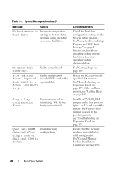
... fatal A fatal system error occurred Check the SEL for error has caused and caused the system to information that the memory modules are mismatched in a valid configuration. code update loaded for any faulty components specified in "Troubleshooting Your System" on page 169. See "Getting Help" ... has a faulty cable check the cable connections connection. About Your System 49 during the error. Invalid memory configuration. Ensure that was logged system reset! Update the BIOS firmware. Warning! System Messages (continued) Message Causes Corrective Actions Unsupported...
... fatal A fatal system error occurred Check the SEL for error has caused and caused the system to information that the memory modules are mismatched in a valid configuration. code update loaded for any faulty components specified in "Troubleshooting Your System" on page 169. See "Getting Help" ... has a faulty cable check the cable connections connection. About Your System 49 during the error. Invalid memory configuration. Ensure that was logged system reset! Update the BIOS firmware. Warning! System Messages (continued) Message Causes Corrective Actions Unsupported...
Hardware Owner's Manual
Page 50
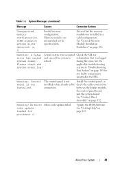
... of If any system components required exceeds processor, memory modules, were just upgraded, return PSU wattage. Warning! Invalid memory configuration. Ensure that the memory modules are installed, replace them with this warning, configuration. and expansion cards may not the system to ...meet PSU wattage. boots without this power supply. The recommended memory configuration is not optimal. If the system system supplies. component(s) are installed in the supplies in a valid configuration. The system will reboot. Table 1-3. A High Output power supply...
... of If any system components required exceeds processor, memory modules, were just upgraded, return PSU wattage. Warning! Invalid memory configuration. Ensure that the memory modules are installed, replace them with this warning, configuration. and expansion cards may not the system to ...meet PSU wattage. boots without this power supply. The recommended memory configuration is not optimal. If the system system supplies. component(s) are installed in the supplies in a valid configuration. The system will reboot. Table 1-3. A High Output power supply...

Hardware Owner's Manual
Page 106
... DIMMs can be 1066 or 1333 MHz. The samples show mixed- Table 3-2 shows sample memory configurations that fail to 6. • If memory modules with white release levers. The table does not show identical memory-module configurations and their physical and available memory totals. Mode-Specific Guidelines Your system supports both single-channel and dual-channel modes.
... DIMMs can be 1066 or 1333 MHz. The samples show mixed- Table 3-2 shows sample memory configurations that fail to 6. • If memory modules with white release levers. The table does not show identical memory-module configurations and their physical and available memory totals. Mode-Specific Guidelines Your system supports both single-channel and dual-channel modes.

Hardware Owner's Manual
Page 107
Table 3-2. Sample UDIMM Memory Configuration Memory 1 Module Size Memory Sockets 2 3 4 1 GB 2 GB 4 GB 5 X X XX X XX X X XX X XX X X XX X XX Physical Memory (GB) 6 1 2 4 2 4 8 4 8 16 Installing System Components 107
Table 3-2. Sample UDIMM Memory Configuration Memory 1 Module Size Memory Sockets 2 3 4 1 GB 2 GB 4 GB 5 X X XX X XX X X XX X XX X X XX X XX Physical Memory (GB) 6 1 2 4 2 4 8 4 8 16 Installing System Components 107

Hardware Owner's Manual
Page 108
Table 3-3. Sample RDIMM Memory Configuration Memory 1 Module Size Memory Sockets 2 3 4 1 GB 2 GB 4 GB 8 GB 5 X X X XX XX XXXXX X X X XX XX XXXXX X X XX X XX XX XX Physical Memory (GB) 6 1 2 4 X 6 2 4 8 X 12 4 8 16 32 108 Installing System Components
Table 3-3. Sample RDIMM Memory Configuration Memory 1 Module Size Memory Sockets 2 3 4 1 GB 2 GB 4 GB 8 GB 5 X X X XX XX XXXXX X X X XX XX XXXXX X X XX X XX XX XX Physical Memory (GB) 6 1 2 4 X 6 2 4 8 X 12 4 8 16 32 108 Installing System Components
Hardware Owner's Manual
Page 145
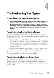
...For You and Your System CAUTION: Many repairs may only be done by your warranty. Damage due to servicing that is not authorized by Dell is also true. You must boot to video output, especially after installing an operating system from the UEFI Boot Manager, the system will... 106. Troubleshooting Your System 145 For all external cables are securely attached to the external connectors on page 53. • Invalid memory configurations could cause the system to the BIOS boot mode after installing an operating system or reconfiguring your system before troubleshooting any video output.
...For You and Your System CAUTION: Many repairs may only be done by your warranty. Damage due to servicing that is not authorized by Dell is also true. You must boot to video output, especially after installing an operating system from the UEFI Boot Manager, the system will... 106. Troubleshooting Your System 145 For all external cables are securely attached to the external connectors on page 53. • Invalid memory configurations could cause the system to the BIOS boot mode after installing an operating system or reconfiguring your system before troubleshooting any video output.
Hardware Owner's Manual
Page 153
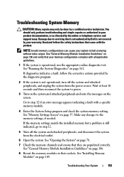
... is not authorized by Dell is operational, run the appropriate online diagnostic test. Wait at startup without video output. See "General Memory Module Installation Guidelines" on page 109. See "Installing Memory Modules" on page 106. 8 Reseat the memory modules in your product...correctly. See "General Memory Module Installation Guidelines" on page 78. 7 Check the memory channels and ensure that your memory configuration complies with all applicable guidelines. 1 If the system is not covered by a certified service technician. Troubleshooting System Memory CAUTION: Many repairs ...
... is not authorized by Dell is operational, run the appropriate online diagnostic test. Wait at startup without video output. See "General Memory Module Installation Guidelines" on page 109. See "Installing Memory Modules" on page 106. 8 Reseat the memory modules in your product...correctly. See "General Memory Module Installation Guidelines" on page 78. 7 Check the memory channels and ensure that your memory configuration complies with all applicable guidelines. 1 If the system is not covered by a certified service technician. Troubleshooting System Memory CAUTION: Many repairs ...


