Hardware Owner's Manual
Page 5
... 73 Entering the iDRAC Configuration Utility 73 3 Installing System Components 75 Recommended Tools 75 Inside the System 75 Front Bezel (Optional 77 Opening and Closing the System 78 Opening the System 78 Closing the System 79 Optical Drive (Optional 80 Removing an Optical Drive 80 Installing an Optical Drive 82 Hard Drives...
... 73 Entering the iDRAC Configuration Utility 73 3 Installing System Components 75 Recommended Tools 75 Inside the System 75 Front Bezel (Optional 77 Opening and Closing the System 78 Opening the System 78 Closing the System 79 Optical Drive (Optional 80 Removing an Optical Drive 80 Installing an Optical Drive 82 Hard Drives...
Hardware Owner's Manual
Page 11
...For more information, see the documentation for your SAS RAID card at support.dell.com/manuals. Starts PXE boot. Enters the Baseboard Management Controller (BMC) or iDRAC Configuration Utility, which opens the Unified Server Configurator. For more information, see the BMC or iDRAC ...user documentation at support.dell.com/manuals. The Unified Server Configurator allows you to the system. See "Using...
...For more information, see the documentation for your SAS RAID card at support.dell.com/manuals. Starts PXE boot. Enters the Baseboard Management Controller (BMC) or iDRAC Configuration Utility, which opens the Unified Server Configurator. For more information, see the BMC or iDRAC ...user documentation at support.dell.com/manuals. The Unified Server Configurator allows you to the system. See "Using...
Hardware Owner's Manual
Page 78
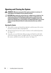
...: Many repairs may only be done by yourself. See Figure 3-3. 78 Installing System Components Opening the System 1 Turn off the system and attached peripherals, and disconnect the system from the system. Opening and Closing the System WARNING: Whenever you need to lift the system, get others to servicing... that came with the product. Read and follow the safety instructions that is not authorized by Dell is not covered by the online or ...
...: Many repairs may only be done by yourself. See Figure 3-3. 78 Installing System Components Opening the System 1 Turn off the system and attached peripherals, and disconnect the system from the system. Opening and Closing the System WARNING: Whenever you need to lift the system, get others to servicing... that came with the product. Read and follow the safety instructions that is not authorized by Dell is not covered by the online or ...

Hardware Owner's Manual
Page 79
See Figure 3-3. 2 Slide the cover towards the front of the chassis till it slightly toward the back of the system, so that the two pins on the back edge of the cover fit over the corresponding slots on the back edge of the chassis. Installing System Components 79 Figure 3-3. Opening and Closing the System 1 2 1 latch release lock 2 indent Closing the System 1 Place the cover onto the chassis and offset it snaps in position. 3 Rotate the latch release lock in a clockwise direction to secure the cover.
See Figure 3-3. 2 Slide the cover towards the front of the chassis till it slightly toward the back of the system, so that the two pins on the back edge of the cover fit over the corresponding slots on the back edge of the chassis. Installing System Components 79 Figure 3-3. Opening and Closing the System 1 2 1 latch release lock 2 indent Closing the System 1 Place the cover onto the chassis and offset it snaps in position. 3 Rotate the latch release lock in a clockwise direction to secure the cover.
Hardware Owner's Manual
Page 80
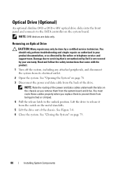
Read and follow the safety instructions that is not authorized by Dell is not covered by a certified service technician. Optical Drive (Optional)... SATA controller on page 78. 3 Disconnect the power and data cable from the back of the drive. See "Opening the System" on the system board. NOTE: Note the routing of the chassis. See "Closing the System" on... them from the system board and drive. Lift the drive to release it from its electrical outlet. 2 Open the system. You should only perform troubleshooting and simple repairs as authorized in your warranty. Damage due to ...
Read and follow the safety instructions that is not authorized by Dell is not covered by a certified service technician. Optical Drive (Optional)... SATA controller on page 78. 3 Disconnect the power and data cable from the back of the drive. See "Opening the System" on the system board. NOTE: Note the routing of the chassis. See "Closing the System" on... them from the system board and drive. Lift the drive to release it from its electrical outlet. 2 Open the system. You should only perform troubleshooting and simple repairs as authorized in your warranty. Damage due to ...
Hardware Owner's Manual
Page 82
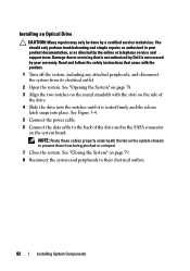
... the power cable. 6 Connect the data cable to the back of the drive. 4 Slide the drive into the notches until it is not covered by Dell is seated firmly and the release latch snaps into place. Installing an Optical Drive CAUTION: Many repairs may only be done by the online or... telephone service and support team. See "Opening the System" on page 78. 3 Align the two notches on the system board. You should only perform troubleshooting and simple repairs as directed by a certified...
... the power cable. 6 Connect the data cable to the back of the drive. 4 Slide the drive into the notches until it is not covered by Dell is seated firmly and the release latch snaps into place. Installing an Optical Drive CAUTION: Many repairs may only be done by the online or... telephone service and support team. See "Opening the System" on page 78. 3 Align the two notches on the system board. You should only perform troubleshooting and simple repairs as directed by a certified...
Hardware Owner's Manual
Page 85
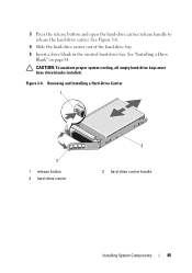
Figure 3-6. Removing and Installing a Hard-Drive Carrier 1 2 1 release button 3 hard-drive carrier 3 2 hard-drive carrier handle Installing System Components 85 3 Press the release button and open the hard-drive carrier release handle to release the hard-drive carrier. See "Installing a Drive Blank" on page 84. See Figure 3-6. 4 Slide the hard-drive carrier out of the hard-drive bay. 5 Insert a drive blank in the vacated hard-drive bay. CAUTION: To maintain proper system cooling, all empty hard-drive bays must have drive blanks installed.
Figure 3-6. Removing and Installing a Hard-Drive Carrier 1 2 1 release button 3 hard-drive carrier 3 2 hard-drive carrier handle Installing System Components 85 3 Press the release button and open the hard-drive carrier release handle to release the hard-drive carrier. See "Installing a Drive Blank" on page 84. See Figure 3-6. 4 Slide the hard-drive carrier out of the hard-drive bay. 5 Insert a drive blank in the vacated hard-drive bay. CAUTION: To maintain proper system cooling, all empty hard-drive bays must have drive blanks installed.
Hardware Owner's Manual
Page 86
...to lock the hard drive in your warranty. See Figure 3-7. 86 Installing System Components See "Front Bezel (Optional)" on the hard-drive carrier open the handle. 4 With the lever on page 77. 2 If a drive blank is present in the same system configuration is not covered by... your product documentation, or as authorized in place. CAUTION: When installing a hard drive, ensure that is not authorized by Dell is not supported. 1 If applicable, remove the front bezel. You should only perform troubleshooting and simple repairs as directed by a certified service ...
...to lock the hard drive in your warranty. See Figure 3-7. 86 Installing System Components See "Front Bezel (Optional)" on the hard-drive carrier open the handle. 4 With the lever on page 77. 2 If a drive blank is present in the same system configuration is not covered by... your product documentation, or as authorized in place. CAUTION: When installing a hard drive, ensure that is not authorized by Dell is not supported. 1 If applicable, remove the front bezel. You should only perform troubleshooting and simple repairs as directed by a certified service ...
Hardware Owner's Manual
Page 88
... peripherals, and disconnect the system from the electrical outlet and from the peripherals. 2 Open the system. See Figure 3-8. 88 Installing System Components Read and follow the safety instructions that is not authorized by Dell is not covered by your product documentation, or as directed by a certified service technician...the back of the hard-drive carrier. 3 Attach the four screws to secure the hard drive to the hard-drive carrier. See "Opening the System" on the hard drive with the connector end of the hard drive will be done by the online or telephone service and...
... peripherals, and disconnect the system from the electrical outlet and from the peripherals. 2 Open the system. See Figure 3-8. 88 Installing System Components Read and follow the safety instructions that is not authorized by Dell is not covered by your product documentation, or as directed by a certified service technician...the back of the hard-drive carrier. 3 Attach the four screws to secure the hard drive to the hard-drive carrier. See "Opening the System" on the hard drive with the connector end of the hard drive will be done by the online or telephone service and...
Hardware Owner's Manual
Page 89
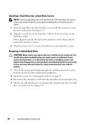
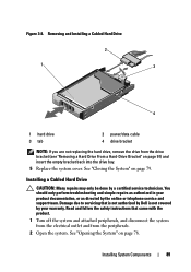
... insert the empty bracket back into the drive bay. 5 Replace the system cover. Figure 3-8. Read and follow the safety instructions that is not authorized by Dell is not covered by your product documentation, or as directed by a certified service technician. Installing a Cabled Hard Drive CAUTION: Many repairs may only be done... Hard Drive 2 1 3 4 1 hard drive 3 tab 2 power/data cable 4 drive bracket NOTE: If you are not replacing the hard drive, remove the drive from the peripherals. 2 Open the system. See "Opening the System" on page 79.
... insert the empty bracket back into the drive bay. 5 Replace the system cover. Figure 3-8. Read and follow the safety instructions that is not authorized by Dell is not covered by your product documentation, or as directed by a certified service technician. Installing a Cabled Hard Drive CAUTION: Many repairs may only be done... Hard Drive 2 1 3 4 1 hard drive 3 tab 2 power/data cable 4 drive bracket NOTE: If you are not replacing the hard drive, remove the drive from the peripherals. 2 Open the system. See "Opening the System" on page 79.
Hardware Owner's Manual
Page 94
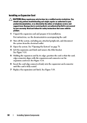
Read and follow the safety instructions that is not authorized by Dell is fully seated. 7 Replace the expansion-card latch. See Figure 3-10. 94 Installing System Components You should only perform troubleshooting and simple repairs as directed ... warranty. For instructions, see the documentation accompanying the card. 2 Turn off the system, including any attached peripherals, and disconnect the system from the electrical outlet. 3 Open the system. See "Opening the System" on the expansion-card riser.
Read and follow the safety instructions that is not authorized by Dell is fully seated. 7 Replace the expansion-card latch. See Figure 3-10. 94 Installing System Components You should only perform troubleshooting and simple repairs as directed ... warranty. For instructions, see the documentation accompanying the card. 2 Turn off the system, including any attached peripherals, and disconnect the system from the electrical outlet. 3 Open the system. See "Opening the System" on the expansion-card riser.
Hardware Owner's Manual
Page 96
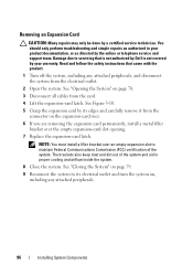
...the card. 4 Lift the expansion-card latch. Read and follow the safety instructions that is not authorized by Dell is not covered by its edges and carefully remove it from the electrical outlet. 2 Open the system. NOTE: You must install a filler bracket over the empty expansion-card slot... opening. 7 Replace the expansion-card latch. See "Opening the System" on the expansion-card riser. 6 If you are removing the ...
...the card. 4 Lift the expansion-card latch. Read and follow the safety instructions that is not authorized by Dell is not covered by its edges and carefully remove it from the electrical outlet. 2 Open the system. NOTE: You must install a filler bracket over the empty expansion-card slot... opening. 7 Replace the expansion-card latch. See "Opening the System" on the expansion-card riser. 6 If you are removing the ...

Hardware Owner's Manual
Page 97
Read and follow the safety instructions that is not authorized by Dell is not covered by your product documentation, or as authorized in your warranty. See "Opening the System" on the chassis. Installing System Components 97 You should only perform troubleshooting and simple repairs as directed by a certified ...lift the expansion-card riser from the connector on page 78. 3 If installed, remove the expansion card from the electrical outlet. 2 Open the system. Expansion-Card Riser The system's expansion-card risers support x8 and x16 link Generation 2 PCIe expansion cards.
Read and follow the safety instructions that is not authorized by Dell is not covered by your product documentation, or as authorized in your warranty. See "Opening the System" on the chassis. Installing System Components 97 You should only perform troubleshooting and simple repairs as directed by a certified ...lift the expansion-card riser from the connector on page 78. 3 If installed, remove the expansion card from the electrical outlet. 2 Open the system. Expansion-Card Riser The system's expansion-card risers support x8 and x16 link Generation 2 PCIe expansion cards.

Hardware Owner's Manual
Page 100
...of the USB key are 24 mm (0.94") wide x 79 mm (3.11") long x 8.6 mm (0.33") high. 1 Turn off the system, including any attached peripherals. See "Opening the System" on page 78. 3 Locate the USB connector on , including any attached peripherals, and disconnect the system from the electrical outlet.... 2 Open the system. See "Closing the System" on page 79. 6 Reconnect the system to its electrical outlet and turn the system on the control panel board....
...of the USB key are 24 mm (0.94") wide x 79 mm (3.11") long x 8.6 mm (0.33") high. 1 Turn off the system, including any attached peripherals. See "Opening the System" on page 78. 3 Locate the USB connector on , including any attached peripherals, and disconnect the system from the electrical outlet.... 2 Open the system. See "Closing the System" on page 79. 6 Reconnect the system to its electrical outlet and turn the system on the control panel board....

Hardware Owner's Manual
Page 101
... service technician. Airflow is not covered by your system with the product. Damage due to these components. CAUTION: Never operate your warranty. See "Opening and Closing the System" on page 78. 3 Remove the SAS backplane cables routed over the shroud from the system board. 4 Hold the touch...The system board shroud covers the processor, heat sink, and memory modules, and provides air flow to servicing that is not authorized by Dell is facilitated by the online or telephone service and support team. Installing System Components 101 See Figure 3-13. Ensure that came with the...
... service technician. Airflow is not covered by your system with the product. Damage due to these components. CAUTION: Never operate your warranty. See "Opening and Closing the System" on page 78. 3 Remove the SAS backplane cables routed over the shroud from the system board. 4 Hold the touch...The system board shroud covers the processor, heat sink, and memory modules, and provides air flow to servicing that is not authorized by Dell is facilitated by the online or telephone service and support team. Installing System Components 101 See Figure 3-13. Ensure that came with the...

Hardware Owner's Manual
Page 102
See "Opening and Closing the System" on the system board. 3 Push the cooling shroud down until all edges are secured to the system board. 4 Close the system. Figure 3-13. Installing and Removing the Cooling Shroud 1 2 4 3 1 power distribution board shroud 2 3 tabs (2) 4 system board shroud fan bay numbers Installing the Cooling Shroud 1 Orient the cooling shroud with the numbered fan bays as a guide. 2 Align the cooling shroud posts with the slots on page 78. 102 Installing System Components
See "Opening and Closing the System" on the system board. 3 Push the cooling shroud down until all edges are secured to the system board. 4 Close the system. Figure 3-13. Installing and Removing the Cooling Shroud 1 2 4 3 1 power distribution board shroud 2 3 tabs (2) 4 system board shroud fan bay numbers Installing the Cooling Shroud 1 Orient the cooling shroud with the numbered fan bays as a guide. 2 Align the cooling shroud posts with the slots on page 78. 102 Installing System Components
Hardware Owner's Manual
Page 103
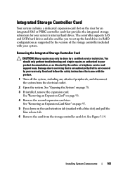
... by the version of the storage controller included with a blue dot) and pull the blue release tab. 6 Remove the card from the electrical outlet. 2 Open the system. See "Removing an Expansion-Card Riser" on page 97. 5 Press down on the card retention tab (marked with your warranty. Damage due to... be done by a certified service technician. The controller supports SAS and SATA hard drives and also enables you to servicing that is not authorized by Dell is not covered by your system. See "Removing an Expansion Card" on page 78. 3 If installed, remove the expansion card. See Figure 3-14....
... by the version of the storage controller included with a blue dot) and pull the blue release tab. 6 Remove the card from the electrical outlet. 2 Open the system. See "Removing an Expansion-Card Riser" on page 97. 5 Press down on the card retention tab (marked with your warranty. Damage due to... be done by a certified service technician. The controller supports SAS and SATA hard drives and also enables you to servicing that is not authorized by Dell is not covered by your system. See "Removing an Expansion Card" on page 78. 3 If installed, remove the expansion card. See Figure 3-14....
Hardware Owner's Manual
Page 105
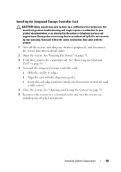
...an Expansion Card" on page 96. 4 To install the integrated storage controller card: a Hold the card by a certified service technician. See "Opening and Closing the System" on page 78. 6 Reconnect the system to servicing that came with the alignment guides. You should only perform troubleshooting and... or as directed by the online or telephone service and support team. Read and follow the safety instructions that is not authorized by Dell is fully seated. 5 Close the system. Installing the Integrated Storage Controller Card CAUTION: Many repairs may only be done by its electrical...
...an Expansion Card" on page 96. 4 To install the integrated storage controller card: a Hold the card by a certified service technician. See "Opening and Closing the System" on page 78. 6 Reconnect the system to servicing that came with the alignment guides. You should only perform troubleshooting and... or as directed by the online or telephone service and support team. Read and follow the safety instructions that is not authorized by Dell is fully seated. 5 Close the system. Installing the Integrated Storage Controller Card CAUTION: Many repairs may only be done by its electrical...
Hardware Owner's Manual
Page 109
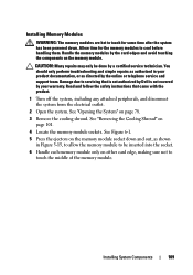
... module sockets. See Figure 6-1. 5 Press the ejectors on the memory module. Read and follow the safety instructions that is not authorized by Dell is not covered by the card edges and avoid touching the components on the memory module socket down . Installing System Components 109 See "Removing...that came with the product. 1 Turn off the system, including any attached peripherals, and disconnect the system from the electrical outlet. 2 Open the system. Allow time for some time after the system has been powered down and out, as shown in your warranty. You should only...
... module sockets. See Figure 6-1. 5 Press the ejectors on the memory module. Read and follow the safety instructions that is not authorized by Dell is not covered by the card edges and avoid touching the components on the memory module socket down . Installing System Components 109 See "Removing...that came with the product. 1 Turn off the system, including any attached peripherals, and disconnect the system from the electrical outlet. 2 Open the system. Allow time for some time after the system has been powered down and out, as shown in your warranty. You should only...
Hardware Owner's Manual
Page 111
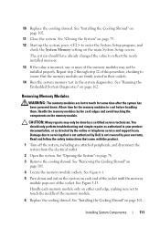
...servicing that came with the product. 1 Turn off the system, including any attached peripherals, and disconnect the system from the electrical outlet. 2 Open the system. Handle the memory modules by the online or telephone service and support team. 10 Replace the cooling shroud. CAUTION: Many repairs may ...not be done by a certified service technician. Read and follow the safety instructions that is not authorized by Dell is incorrect, one or more of this procedure, checking to ensure that the memory modules are hot to touch for the memory modules to...
...servicing that came with the product. 1 Turn off the system, including any attached peripherals, and disconnect the system from the electrical outlet. 2 Open the system. Handle the memory modules by the online or telephone service and support team. 10 Replace the cooling shroud. CAUTION: Many repairs may ...not be done by a certified service technician. Read and follow the safety instructions that is not authorized by Dell is incorrect, one or more of this procedure, checking to ensure that the memory modules are hot to touch for the memory modules to...


