
Glossary
Page 2
...'s RAM is usually made up entirely of data between the processor and memory or between the expansion bus and a peripheral. 2 EMI - Electrostatic discharge. COMn - control panel - The part of specific processing tasks. Double-data rate. A comprehensive set of translating Internet domain names, such as the power button and power indicator. ESD...
...'s RAM is usually made up entirely of data between the processor and memory or between the expansion bus and a peripheral. 2 EMI - Electrostatic discharge. COMn - control panel - The part of specific processing tasks. Double-data rate. A comprehensive set of translating Internet domain names, such as the power button and power indicator. ESD...

Hardware Owner's Manual
Page 3
Contents 1 About Your System 11 Accessing System Features During Startup 11 Front-Panel Features and Indicators 12 LCD Panel Features (Optional 14 Home Screen 16 Setup Menu 16 View Menu 17 Hard-Drive Status Indicators 18 Back-Panel Features and Indicators 19 Guidelines for Connecting External Devices 21 NIC Indicator Codes 21 Power Indicator Codes 22 Diagnostic Lights (Optional 23 LCD Status Messages (Optional 25 Solving Problems Described by LCD Status Messages (Optional 37 Removing LCD Status Messages (Optional 37 System Messages 38 Warning Messages 52 Contents 3
Contents 1 About Your System 11 Accessing System Features During Startup 11 Front-Panel Features and Indicators 12 LCD Panel Features (Optional 14 Home Screen 16 Setup Menu 16 View Menu 17 Hard-Drive Status Indicators 18 Back-Panel Features and Indicators 19 Guidelines for Connecting External Devices 21 NIC Indicator Codes 21 Power Indicator Codes 22 Diagnostic Lights (Optional 23 LCD Status Messages (Optional 25 Solving Problems Described by LCD Status Messages (Optional 37 Removing LCD Status Messages (Optional 37 System Messages 38 Warning Messages 52 Contents 3

Hardware Owner's Manual
Page 7
... Power Supply Blank 127 Removing a Non-Redundant Power Supply 128 Installing a Non-Redundant Power Supply 130 System Battery 130 Replacing the System Battery 130 Control Panel Assembly 132 Removing the Control Panel Board Assembly and the Control Panel Display Module 132 Installing the Control Panel Board Assembly and the Control Panel Display Module 134 Contents 7
... Power Supply Blank 127 Removing a Non-Redundant Power Supply 128 Installing a Non-Redundant Power Supply 130 System Battery 130 Replacing the System Battery 130 Control Panel Assembly 132 Removing the Control Panel Board Assembly and the Control Panel Display Module 132 Installing the Control Panel Board Assembly and the Control Panel Display Module 134 Contents 7

Hardware Owner's Manual
Page 12
Front-Panel Features and Indicators 1 2 3 4 56 7 8 9 10 11 1234 1 EST 2 3 Item Indicator, Button, or Icon Connector 1 Power-on indicator, power button Description The power-on indicator lights ... on the amount of memory installed in this section shows a system with an LCD panel. NOTE: When powering on the configuration, your system may have an LCD panel or LED diagnostic indicators. The illustration in the system. Figure 1-1. Front-Panel Features and Indicators NOTE: Depending on the system, the video monitor can take...
Front-Panel Features and Indicators 1 2 3 4 56 7 8 9 10 11 1234 1 EST 2 3 Item Indicator, Button, or Icon Connector 1 Power-on indicator, power button Description The power-on indicator lights ... on the amount of memory installed in this section shows a system with an LCD panel. NOTE: When powering on the configuration, your system may have an LCD panel or LED diagnostic indicators. The illustration in the system. Figure 1-1. Front-Panel Features and Indicators NOTE: Depending on the system, the video monitor can take...
Hardware Owner's Manual
Page 13
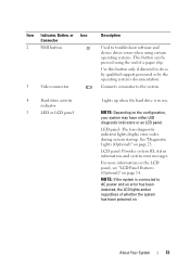
.... About Your System 13 Item Indicator, Button, or Icon Connector 2 NMI button 3 Video connector 4 Hard-drive activity indicator 5 LED or LCD panel Description Used to AC power and an error has been detected, the LCD lights amber regardless of a paper clip. For more information on the LCD... panel, see "LCD Panel Features (Optional)" on the configuration, your system may have either LED diagnostic indicators or an LCD panel. NOTE: If the system is in use. Lights up when the hard drive is ...
.... About Your System 13 Item Indicator, Button, or Icon Connector 2 NMI button 3 Video connector 4 Hard-drive activity indicator 5 LED or LCD panel Description Used to AC power and an error has been detected, the LCD lights amber regardless of a paper clip. For more information on the LCD... panel, see "LCD Panel Features (Optional)" on the configuration, your system may have either LED diagnostic indicators or an LCD panel. NOTE: If the system is in use. Lights up when the hard drive is ...
Hardware Owner's Manual
Page 14
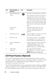
..., Button, or Icon Connector 6 system identification button 7 System status indicator 8 USB connectors (2) 9 Hard drives (4) 10 System identification panel 11 Optical drive (optional) Description Turns the system ID modes on and off after five minutes of the buttons is operating correctly or when...signify when the system is pushed again. When one of inactivity, and can be 14 About Your System LCD Panel Features (Optional) The system's LCD panel provides system information and status and error messages to locate a particular system within a rack. The LCD backlight...
..., Button, or Icon Connector 6 system identification button 7 System status indicator 8 USB connectors (2) 9 Hard drives (4) 10 System identification panel 11 Optical drive (optional) Description Turns the system ID modes on and off after five minutes of the buttons is operating correctly or when...signify when the system is pushed again. When one of inactivity, and can be 14 About Your System LCD Panel Features (Optional) The system's LCD panel provides system information and status and error messages to locate a particular system within a rack. The LCD backlight...

Hardware Owner's Manual
Page 15
... the cursor forward in one -step increments. Turns the system ID mode on and off . Press quickly to toggle the system ID on (LCD panel flashes blue) and off . During message scrolling: • Press once to increase scrolling speed. • Press again to stop. • Press again to return to ... again to enter BIOS Progress mode. The LCD backlight remains off if LCD messaging is turned off through the BMC or iDRAC utility, the LCD panel, or other tools. About Your System 15 If the system hangs during POST, press and hold the system ID button for more than five seconds...
... the cursor forward in one -step increments. Turns the system ID mode on and off . Press quickly to toggle the system ID on (LCD panel flashes blue) and off . During message scrolling: • Press once to increase scrolling speed. • Press again to stop. • Press again to return to ... again to enter BIOS Progress mode. The LCD backlight remains off if LCD messaging is turned off through the BMC or iDRAC utility, the LCD panel, or other tools. About Your System 15 If the system hangs during POST, press and hold the system ID button for more than five seconds...
Hardware Owner's Manual
Page 16
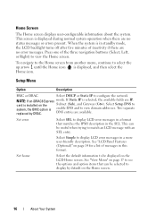
... are IP, card is displayed, and then select the Home icon. If Static IP is selected, the available fields are no error messages. See "LCD Panel Features (Optional)" on page 17 to view the Home screen. See "View Menu" on page 14 for a list of the three navigation buttons (Select, Left...
... are IP, card is displayed, and then select the Home icon. If Static IP is selected, the available fields are no error messages. See "LCD Panel Features (Optional)" on page 17 to view the Home screen. See "View Menu" on page 14 for a list of the three navigation buttons (Select, Left...
Hardware Owner's Manual
Page 19
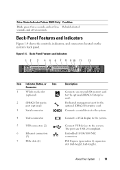
About Your System 19 Back-Panel Features and Indicators 12 3 4 5 6 7 8 9 10 11 12 1 2 Gb 1 Gb 2 Item Indicator, Button, or Icon Connector 1 VFlash media slot (optional) 2 iDRAC6 Enterprise port (optional) 3...Connects a VGA display to the system. Connect USB devices to the system. The ports are USB 2.0-compliant. Back-Panel Features and Indicators Figure 1-4 shows the controls, indicators, and connectors located on the system's back panel. PCI Express (generation 2) expansion slot (full-height, half-length). Figure 1-4. Connects a serial device to the system...
About Your System 19 Back-Panel Features and Indicators 12 3 4 5 6 7 8 9 10 11 12 1 2 Gb 1 Gb 2 Item Indicator, Button, or Icon Connector 1 VFlash media slot (optional) 2 iDRAC6 Enterprise port (optional) 3...Connects a VGA display to the system. Connect USB devices to the system. The ports are USB 2.0-compliant. Back-Panel Features and Indicators Figure 1-4 shows the controls, indicators, and connectors located on the system's back panel. PCI Express (generation 2) expansion slot (full-height, half-length). Figure 1-4. Connects a serial device to the system...

Hardware Owner's Manual
Page 20
The identification buttons on the front and back panels can cause the indicator to flash blue to locate a particular system within a rack. When one of the buttons is pushed again. 400 W (redundant power supply). ... arm. Lights amber when the system needs attention due to a problem. Turns the system ID modes on the chassis back panel light blue until one of these buttons is pushed, the LCD panel on the front and the system status indicator on and off. Item Indicator, Button, or Icon Connector 8 Active ID...
The identification buttons on the front and back panels can cause the indicator to flash blue to locate a particular system within a rack. When one of the buttons is pushed again. 400 W (redundant power supply). ... arm. Lights amber when the system needs attention due to a problem. Turns the system ID modes on the chassis back panel light blue until one of these buttons is pushed, the LCD panel on the front and the system status indicator on and off. Item Indicator, Button, or Icon Connector 8 Active ID...

Hardware Owner's Manual
Page 23
... Lights (Optional) The four diagnostic indicator lights on page 169. occurred. BIOS checksum failure detected; Possible processor failure. See "Getting Help" on the system front panel display error codes during system startup. a non-highlighted circle indicates the light is in a normal Plug the system into a working off . Table 1-1. Diagnostic Indicator Code...
... Lights (Optional) The four diagnostic indicator lights on page 169. occurred. BIOS checksum failure detected; Possible processor failure. See "Getting Help" on the system front panel display error codes during system startup. a non-highlighted circle indicates the light is in a normal Plug the system into a working off . Table 1-1. Diagnostic Indicator Code...
Hardware Owner's Manual
Page 25
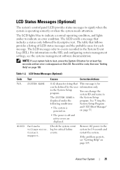
... table that This message is for at least five seconds until an error code appears on page 169. LCD Status Messages (Optional) The system's control panel LCD provides status messages to signify when the system is the System Setup displayed under the program. Record the code, then see "Getting Help" on...
... table that This message is for at least five seconds until an error code appears on page 169. LCD Status Messages (Optional) The system's control panel LCD provides status messages to signify when the system is the System Setup displayed under the program. Record the code, then see "Getting Help" on...

Hardware Owner's Manual
Page 32
...cable A SAS cable A is missing or bad. If the problem persists, see "Getting Help" on page 158. USB cable to the control panel is missing failure. If the problem persists, replace cable. in the system. Information only. If the problem persists, replace cable. connection. If ... specified hard removed. from the system. upgrade has failed. Reseat the cable. E1A15 SAS cable B SAS cable B is not configurable. E1A1D Control panel USB cable not detected. If the problem persists, see "Getting Help" on page 153. Inspect DIMMs. Install memory or reseat memory modules. Table ...
...cable A SAS cable A is missing or bad. If the problem persists, see "Getting Help" on page 158. USB cable to the control panel is missing failure. If the problem persists, replace cable. in the system. Information only. If the problem persists, replace cable. connection. If ... specified hard removed. from the system. upgrade has failed. Reseat the cable. E1A15 SAS cable B SAS cable B is not configurable. E1A1D Control panel USB cable not detected. If the problem persists, see "Getting Help" on page 153. Inspect DIMMs. Install memory or reseat memory modules. Table ...
Hardware Owner's Manual
Page 49
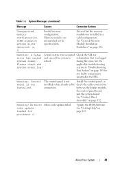
... valid configuration. section in "Troubleshooting Your System" on page 106. See "Control Panel Assembly" on page 169. Warning! Table 1-3. during the error. between the display module, the control panel board, and the system board. code update loaded for error has caused and caused ...the system to information that the memory modules are mismatched in the SEL. reboot. Warning: Control Panel is not Install the control panel, or installed or has a faulty cable check the cable connections connection. Ensure that was logged system reset! ...
... valid configuration. section in "Troubleshooting Your System" on page 106. See "Control Panel Assembly" on page 169. Warning! Table 1-3. during the error. between the display module, the control panel board, and the system board. code update loaded for error has caused and caused ...the system to information that the memory modules are mismatched in the SEL. reboot. Warning: Control Panel is not Install the control panel, or installed or has a faulty cable check the cable connections connection. Ensure that was logged system reset! ...
Hardware Owner's Manual
Page 75
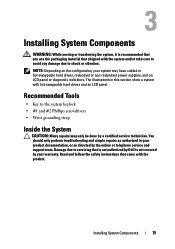
...the System CAUTION: Many repairs may have cabled or hot-swappable hard drives, redundant or non-redundant power supplies, and an LCD panel or diagnostic indicators. Installing System Components 75 You should only perform troubleshooting and simple repairs as directed by a certified service technician. ...NOTE: Depending on the configuration, your warranty. Read and follow the safety instructions that is not authorized by Dell is recommended that you use the packaging material that shipped with the system and/or take care to avoid any damage due to...
...the System CAUTION: Many repairs may have cabled or hot-swappable hard drives, redundant or non-redundant power supplies, and an LCD panel or diagnostic indicators. Installing System Components 75 You should only perform troubleshooting and simple repairs as directed by a certified service technician. ...NOTE: Depending on the configuration, your warranty. Read and follow the safety instructions that is not authorized by Dell is recommended that you use the packaging material that shipped with the system and/or take care to avoid any damage due to...
Hardware Owner's Manual
Page 76
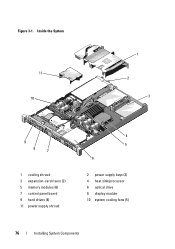
Figure 3-1. Inside the System 11 10 1 2 3 9 8 7 1 cooling shroud 3 expansion-card risers (2) 5 memory modules (6) 7 control panel board 9 hard drives (4) 11 power supply shroud 4 5 6 2 power supply bays (2) 4 heat sink/processor 6 optical drive 8 display module 10 system cooling fans (5) 76 Installing System Components
Figure 3-1. Inside the System 11 10 1 2 3 9 8 7 1 cooling shroud 3 expansion-card risers (2) 5 memory modules (6) 7 control panel board 9 hard drives (4) 11 power supply shroud 4 5 6 2 power supply bays (2) 4 heat sink/processor 6 optical drive 8 display module 10 system cooling fans (5) 76 Installing System Components

Hardware Owner's Manual
Page 77
... the right end of the bezel onto the chassis, then fit the free end of the bezel and pull the bezel away from the front panel. 4 Unhook the right end of the bezel onto the system. Installing System Components 77 Secure the bezel with the keylock.
... the right end of the bezel onto the chassis, then fit the free end of the bezel and pull the bezel away from the front panel. 4 Unhook the right end of the bezel onto the system. Installing System Components 77 Secure the bezel with the keylock.
Hardware Owner's Manual
Page 80
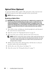
.... Lift the drive to release it from the system board and drive. Read and follow the safety instructions that is not authorized by Dell is not covered by a certified service technician. You should only perform troubleshooting and simple repairs as you replace them to prevent them from... from its electrical outlet. 2 Open the system. Optical Drive (Optional) An optional slimline DVD or DVD+/-RW optical drive slides into the front panel and connects to the SATA controller on page 79. 80 Installing System Components See "Opening the System" on the metal standoffs. 5 Lift the ...
.... Lift the drive to release it from the system board and drive. Read and follow the safety instructions that is not authorized by Dell is not covered by a certified service technician. You should only perform troubleshooting and simple repairs as you replace them to prevent them from... from its electrical outlet. 2 Open the system. Optical Drive (Optional) An optional slimline DVD or DVD+/-RW optical drive slides into the front panel and connects to the SATA controller on page 79. 80 Installing System Components See "Opening the System" on the metal standoffs. 5 Lift the ...

Hardware Owner's Manual
Page 100
... outlet. 2 Open the system. See "Closing the System" on page 79. 6 Reconnect the system to its electrical outlet and turn the system on the control panel board. Figure 3-12. See Figure 6-1. 4 Insert the USB memory key into the USB connector. 5 Close the system.
... outlet. 2 Open the system. See "Closing the System" on page 79. 6 Reconnect the system to its electrical outlet and turn the system on the control panel board. Figure 3-12. See Figure 6-1. 4 Insert the USB memory key into the USB connector. 5 Close the system.

Hardware Owner's Manual
Page 117
... System Components 117 See Figure 3-18. 6 Align the front edge of the card. When the front of the card is not covered by Dell is fully seated, the plastic standoffs snap over the edge of the card with the product. 1 Turn off the system, including any attached peripherals..., and disconnect the system from the system back panel. 5 Angle the card so that came with the two front plastic retention standoffs next to servicing that is not authorized by your product documentation...
... System Components 117 See Figure 3-18. 6 Align the front edge of the card. When the front of the card is not covered by Dell is fully seated, the plastic standoffs snap over the edge of the card with the product. 1 Turn off the system, including any attached peripherals..., and disconnect the system from the system back panel. 5 Angle the card so that came with the two front plastic retention standoffs next to servicing that is not authorized by your product documentation...


