Rack Installation Guide
Page 8
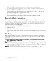
... and VersaRails rack kits are similar. One rack kit is provided to the rack. The total rack load should not exceed 80 percent of cabinet control may occur. The RapidRails™ rack kit can be installed in the rack cabinet. The procedures for trained service technicians installing one or more systems...
... and VersaRails rack kits are similar. One rack kit is provided to the rack. The total rack load should not exceed 80 percent of cabinet control may occur. The RapidRails™ rack kit can be installed in the rack cabinet. The procedures for trained service technicians installing one or more systems...

Information Update
Page 2
... are registered trademarks of Dell Inc. b Press during startup to the system board is an update to change the setting to either the entities claiming the marks and names or their products. RAC Mode Support When installing an optional Remote Access Controller (RAC) card in ...this document is strictly forbidden. Other trademarks and trade names may be configured only as a dedicated NIC port. Dell Inc. e Press , save your system. Trademarks used in your RAC...
... are registered trademarks of Dell Inc. b Press during startup to the system board is an update to change the setting to either the entities claiming the marks and names or their products. RAC Mode Support When installing an optional Remote Access Controller (RAC) card in ...this document is strictly forbidden. Other trademarks and trade names may be configured only as a dedicated NIC port. Dell Inc. e Press , save your system. Trademarks used in your RAC...

Getting Started Guide
Page 5
... dual-ranked registered 667-MHz DDR2 memory modules with ECC, upgradeable to two 3.5-inch, internal, SATA hard drives with an optional SAS controller card (hot-plug option available). One riser card (left and center risers), each providing a x8 lane width PCI-Express expansion slot....Your System 3 NOTE: Use the System Setup program to two 3.5-inch, internal, Serial-Attached SCSI (SAS) hard drives with the optional SAS controller card (hot-plug option available). - System Features The major hardware and software features of the following riser card options: - Single Core Intel&#...
... dual-ranked registered 667-MHz DDR2 memory modules with ECC, upgradeable to two 3.5-inch, internal, SATA hard drives with an optional SAS controller card (hot-plug option available). One riser card (left and center risers), each providing a x8 lane width PCI-Express expansion slot....Your System 3 NOTE: Use the System Setup program to two 3.5-inch, internal, Serial-Attached SCSI (SAS) hard drives with the optional SAS controller card (hot-plug option available). - System Features The major hardware and software features of the following riser card options: - Single Core Intel&#...

Getting Started Guide
Page 6
... 800 x 600, 1024 x 768, 1280 x 1024. • Optional remote access controller for remote systems management, which provides remote system management, crashed system recovery, and power control functions for Dell PowerEdge. • An integrated VGA-compatible video subsystem with an ATI ES1000, 33-MHz PCI... video controller. true-color graphics are used for the two redundant PSUs (hot...
... 800 x 600, 1024 x 768, 1280 x 1024. • Optional remote access controller for remote systems management, which provides remote system management, crashed system recovery, and power control functions for Dell PowerEdge. • An integrated VGA-compatible video subsystem with an ATI ES1000, 33-MHz PCI... video controller. true-color graphics are used for the two redundant PSUs (hot...

Getting Started Guide
Page 12
... the system. 10 Getting Started With Your System Be sure the operating system is satisfactory. Installing the Bezel Install the bezel (optional). Adjust the monitor's controls until the displayed image is installed before installing hardware or software not purchased with your system. Complete the 0perating System Setup If you purchased a preinstalled...
... the system. 10 Getting Started With Your System Be sure the operating system is satisfactory. Installing the Bezel Install the bezel (optional). Adjust the monitor's controls until the displayed image is installed before installing hardware or software not purchased with your system. Complete the 0perating System Setup If you purchased a preinstalled...

Getting Started Guide
Page 14
... SATA SAS CD/DVD drive USB flash drive Up to two 3.5-inch, internal (optional for hot-plug) Up to two 3.5-inch, internal with optional SAS controller card (optional for integrated 1-Gigabit network adapters) 9 pin Two 4-pin, USB 2.0 compliant 15-pin VGA 15-pin VGA Two 4-pin, USB 2.0 compliant Three 7-pin one...
... SATA SAS CD/DVD drive USB flash drive Up to two 3.5-inch, internal (optional for hot-plug) Up to two 3.5-inch, internal with optional SAS controller card (optional for integrated 1-Gigabit network adapters) 9 pin Two 4-pin, USB 2.0 compliant 15-pin VGA 15-pin VGA Two 4-pin, USB 2.0 compliant Three 7-pin one...

Getting Started Guide
Page 15
... Wattage Voltage Maximum inrush current System battery Physical Height Width Depth With optional bezel Without optional bezel Weight (maximum configuration Kg) Integrated ATI ES1000 VGA controller 32 MB (Min)-64 MB (Max) DDR II 400 W redundant PSU for hot-plug hard drives plus redundant PSU configuration (maximum configuration) 100-240 VAC...
... Wattage Voltage Maximum inrush current System battery Physical Height Width Depth With optional bezel Without optional bezel Weight (maximum configuration Kg) Integrated ATI ES1000 VGA controller 32 MB (Min)-64 MB (Max) DDR II 400 W redundant PSU for hot-plug hard drives plus redundant PSU configuration (maximum configuration) 100-240 VAC...

Hardware Owner's Manual (PDF)
Page 4
... Exit Screen 56 System and Setup Password Features 56 Using the System Password 57 Using the Setup Password 59 Disabling a Forgotten Password 60 Baseboard Management Controller Configuration 61 Entering the BMC Setup Module 61 BMC Setup Module Options 61 3 Installing System Components 63 Recommended Tools 63 Inside the System 64 Front...
... Exit Screen 56 System and Setup Password Features 56 Using the System Password 57 Using the Setup Password 59 Disabling a Forgotten Password 60 Baseboard Management Controller Configuration 61 Entering the BMC Setup Module 61 BMC Setup Module Options 61 3 Installing System Components 63 Recommended Tools 63 Inside the System 64 Front...

Hardware Owner's Manual (PDF)
Page 7
... (Service-only Procedure 113 Removing the Control Panel Assembly 113 Installing the Control Panel Assembly 115 Power Distribution Board 116 Removing the Power Distribution Board 116 Replacing the Power Distribution Board . . . . . 118 System Board (Service-Only Procedure 118 ...
... (Service-only Procedure 113 Removing the Control Panel Assembly 113 Installing the Control Panel Assembly 115 Power Distribution Board 116 Removing the Power Distribution Board 116 Replacing the Power Distribution Board . . . . . 118 System Board (Service-Only Procedure 118 ...

Hardware Owner's Manual (PDF)
Page 8
... Drive 141 Troubleshooting a Hard Drive 142 Troubleshooting a Hot-plug Hard Drive 143 Troubleshooting a SAS or SAS RAID Controller . . . . 145 Troubleshooting Expansion Cards 147 Troubleshooting the Microprocessors 149 5 Running the System Diagnostics 151 Using Dell PowerEdge Diagnostics 151 System Diagnostics Features 151 When to Use the System Diagnostics 152 Running the System Diagnostics 152...
... Drive 141 Troubleshooting a Hard Drive 142 Troubleshooting a Hot-plug Hard Drive 143 Troubleshooting a SAS or SAS RAID Controller . . . . 145 Troubleshooting Expansion Cards 147 Troubleshooting the Microprocessors 149 5 Running the System Diagnostics 151 Using Dell PowerEdge Diagnostics 151 System Diagnostics Features 151 When to Use the System Diagnostics 152 Running the System Diagnostics 152...

Hardware Owner's Manual (PDF)
Page 9
Using Custom Test Options 153 Selecting Devices for Testing 153 Selecting Diagnostics Options 153 Viewing Information and Results 154 6 Jumpers and Connectors 155 System Board Jumpers 155 System Board Connectors 155 Riser Card Connectors 158 Control Panel Assembly Connectors 159 SAS/SATA Backplane Board Connectors 160 Expansion Card Connectors for SAS Controller Daughter Cards 160 Disabling a Forgotten Password 162 7 Getting Help 165 Contacting Dell 165 Glossary 167 Index 179 Contents 9
Using Custom Test Options 153 Selecting Devices for Testing 153 Selecting Diagnostics Options 153 Viewing Information and Results 154 6 Jumpers and Connectors 155 System Board Jumpers 155 System Board Connectors 155 Riser Card Connectors 158 Control Panel Assembly Connectors 159 SAS/SATA Backplane Board Connectors 160 Expansion Card Connectors for SAS Controller Daughter Cards 160 Disabling a Forgotten Password 162 7 Getting Help 165 Contacting Dell 165 Glossary 167 Index 179 Contents 9

Hardware Owner's Manual (PDF)
Page 12
...documentation describes how to install (if necessary), configure, and use of the remote access controller (RAC) card. This keystroke enters the SAS Configuration Utility. See the Dell OpenManage™ Baseboard Management Controller User's Guide for any components you enter the keystroke, allow the system to the ... to describe changes to finish booting, and then restart your system and try again. If your SAS controller User's Guide for more information on support.dell.com and read the updates first because they often supersede information in other documents. • Release notes...
...documentation describes how to install (if necessary), configure, and use of the remote access controller (RAC) card. This keystroke enters the SAS Configuration Utility. See the Dell OpenManage™ Baseboard Management Controller User's Guide for any components you enter the keystroke, allow the system to the ... to describe changes to finish booting, and then restart your system and try again. If your SAS controller User's Guide for more information on support.dell.com and read the updates first because they often supersede information in other documents. • Release notes...

Hardware Owner's Manual (PDF)
Page 13
... the optional bezel. (To remove the bezel, press the latch at the left end of the bezel. Front-Panel Features and Indicators Figure 1-1 shows the controls, indicators, connectors, and features on page 68.) Table 1-2 provides component descriptions. Front-Panel Features and Indicators 1 2 3 45 6 7 8 9 10 11 ...enabled through the System Setup Program (see the documentation for PXE boot. If you to configure NIC settings for your SAS controller card. Figure 1-1. For more information, see "Integrated Devices Screen" on page 51), this keystroke allows you have the optional battery-...
... the optional bezel. (To remove the bezel, press the latch at the left end of the bezel. Front-Panel Features and Indicators Figure 1-1 shows the controls, indicators, connectors, and features on page 68.) Table 1-2 provides component descriptions. Front-Panel Features and Indicators 1 2 3 45 6 7 8 9 10 11 ...enabled through the System Setup Program (see the documentation for PXE boot. If you to configure NIC settings for your SAS controller card. Figure 1-1. For more information, see "Integrated Devices Screen" on page 51), this keystroke allows you have the optional battery-...

Hardware Owner's Manual (PDF)
Page 19
... bay 2 (PS2) system identification button system status indicator connector NIC1 connector (Gb) video connector remote access controller (RAC) connector (optional) Connecting External Devices When connecting external devices to your system, follow these guidelines: ...the device itself.) See the documentation that accompanied the device for specific installation and configuration instructions. Back-Panel Features and Indicators Figure 1-3 shows the controls, indicators, and connectors located on the system's back panel. Figure 1-3. riser card 2 3 power supply bay 1 (PS1) 4 5 redundant...
... bay 2 (PS2) system identification button system status indicator connector NIC1 connector (Gb) video connector remote access controller (RAC) connector (optional) Connecting External Devices When connecting external devices to your system, follow these guidelines: ...the device itself.) See the documentation that accompanied the device for specific installation and configuration instructions. Back-Panel Features and Indicators Figure 1-3 shows the controls, indicators, and connectors located on the system's back panel. Figure 1-3. riser card 2 3 power supply bay 1 (PS1) 4 5 redundant...

Hardware Owner's Manual (PDF)
Page 20
... device while your system and the device are turned off. The indicators on the redundant power supplies show whether power is on the front panel controls the power to the system. Power supply fault Amber indicates a problem with the power supply. See "Using the System Setup Program" on the system (unless...
... device while your system and the device are turned off. The indicators on the redundant power supplies show whether power is on the front panel controls the power to the system. Power supply fault Amber indicates a problem with the power supply. See "Using the System Setup Program" on the system (unless...

Hardware Owner's Manual (PDF)
Page 22
... LCD scrolls a message that can occur and the probable cause for complete information about safety precautions, working inside the system. LCD Status Messages The system's control panel LCD provides status messages to signify when the system is connected to remove the system cover and access any of the components inside the...
... LCD scrolls a message that can occur and the probable cause for complete information about safety precautions, working inside the system. LCD Status Messages The system's control panel LCD provides status messages to signify when the system is connected to remove the system cover and access any of the components inside the...

Hardware Owner's Manual (PDF)
Page 24
... Messages (continued) Code Text Causes Corrective Actions E1211 ROMB Batt RAID battery is no longer fan- page 165. page 165. Check control panel LCD redundant. See "Troubleshooting a SAS or SAS RAID Controller" on page 145, and "Troubleshooting System Cooling Problems" on exceeded the allowable page 165. page 165. Another fan for additional...
... Messages (continued) Code Text Causes Corrective Actions E1211 ROMB Batt RAID battery is no longer fan- page 165. page 165. Check control panel LCD redundant. See "Troubleshooting a SAS or SAS RAID Controller" on page 145, and "Troubleshooting System Cooling Problems" on exceeded the allowable page 165. page 165. Another fan for additional...

Hardware Owner's Manual (PDF)
Page 25
... disconnected and reconnected to the AC power source, or the SEL is out of acceptable temperature range and has halted operation. See the Dell™ OpenManage™ Baseboard Management Controller User's Guide for the most current system information. If the problem persists, see "Getting Help" on page 134. See "Troubleshooting System Cooling...
... disconnected and reconnected to the AC power source, or the SEL is out of acceptable temperature range and has halted operation. See the Dell™ OpenManage™ Baseboard Management Controller User's Guide for the most current system information. If the problem persists, see "Getting Help" on page 134. See "Troubleshooting System Cooling...

Hardware Owner's Manual (PDF)
Page 30
... Err E2012 Unusable Memory E2013 Shadow BIOS Fail E2014 CMOS Fail E2015 DMA Controller E2016 Int Controller E2017 Timer Fail Causes Corrective Actions SAS cable C is not See "Troubleshooting configurable. configuration. DMA controller failure. See "Getting Help" on page 165. The system BIOS failed ...to copy its flash image into memory. See "Getting Help" on subsystem failure. Reseat the cable. Control cable for the power Reseat the cable. If the problem persists, see "Getting Help" on page 165. If the distribution board (PDB...
... Err E2012 Unusable Memory E2013 Shadow BIOS Fail E2014 CMOS Fail E2015 DMA Controller E2016 Int Controller E2017 Timer Fail Causes Corrective Actions SAS cable C is not See "Troubleshooting configurable. configuration. DMA controller failure. See "Getting Help" on page 165. The system BIOS failed ...to copy its flash image into memory. See "Getting Help" on subsystem failure. Reseat the cable. Control cable for the power Reseat the cable. If the problem persists, see "Getting Help" on page 165. If the distribution board (PDB...

Hardware Owner's Manual (PDF)
Page 31
.... See "Getting Help" on page 165. E201E POST Mem Test BIOS POST memory test failure. E201F DRAC Config Dell remote access controller (DRAC) configuration failure. Check screen for specific error messages. Ensure that DRAC cables and connectors are properly seated. Check screen for specific error messages. Check ...
.... See "Getting Help" on page 165. E201E POST Mem Test BIOS POST memory test failure. E201F DRAC Config Dell remote access controller (DRAC) configuration failure. Check screen for specific error messages. Ensure that DRAC cables and connectors are properly seated. Check screen for specific error messages. Check ...

