Information Update - Dell OpenManage™ Server Support Kit Version 4.3 (.pdf)
Page 1
...connector on the system board. CAUTION: To help prevent damage to the system's RAC connector on the system board. See "Opening the System" in the Installation and Troubleshooting Guide for installing the Dell™ Remote Access ...Controller 4/P (DRAC 4/P) card into expansion slot: a Position the DRAC 4/P card so that the system is unplugged from its AC power source. You should be connected only one way. 5 Install the DRAC 4/P card into a Dell PowerEdge...
...connector on the system board. CAUTION: To help prevent damage to the system's RAC connector on the system board. See "Opening the System" in the Installation and Troubleshooting Guide for installing the Dell™ Remote Access ...Controller 4/P (DRAC 4/P) card into expansion slot: a Position the DRAC 4/P card so that the system is unplugged from its AC power source. You should be connected only one way. 5 Install the DRAC 4/P card into a Dell PowerEdge...

Information Update - Dell OpenManage™ Server Support Kit Version 4.3 (.pdf)
Page 2
...system's integrated NIC connector. 9 Reattach the system to the back panel instead of a screw. NOTE: Some systems use may vary on your system board and the actual expansion slot that secures the expansion-card bracket to the card NIC connector on the DRAC 4/P card- Figure 1. c Install the ... the monitor cable to the card video connector on the system. See Figure 2. www.dell.com | support.dell.com b Insert the card-edge connector firmly into the system-board card connector until the card is fully seated. The monitor cable must be connected to the card NIC connector on the DRAC...
...system's integrated NIC connector. 9 Reattach the system to the back panel instead of a screw. NOTE: Some systems use may vary on your system board and the actual expansion slot that secures the expansion-card bracket to the card NIC connector on the DRAC 4/P card- Figure 1. c Install the ... the monitor cable to the card video connector on the system. See Figure 2. www.dell.com | support.dell.com b Insert the card-edge connector firmly into the system-board card connector until the card is fully seated. The monitor cable must be connected to the card NIC connector on the DRAC...

Getting Started Guide
Page 5
... an optional remote access controller (RAC) card. • One 3.5-inch CD, DVD, or combination CD-RW/DVD in four memory module sockets on the system board. • One of the following riser card options: - One full-height, half-length, x8 lane PCIe expansion slot and one full-height, half-length, x8...
... an optional remote access controller (RAC) card. • One 3.5-inch CD, DVD, or combination CD-RW/DVD in four memory module sockets on the system board. • One of the following riser card options: - One full-height, half-length, x8 lane PCIe expansion slot and one full-height, half-length, x8...

Hardware Owner's Manual (PDF)
Page 6
... Panel Assembly (Service-Only Procedure 89 Removing the Control Panel Assembly 89 Installing the Control Panel Assembly 90 System Board (Service-Only Procedure 91 Removing the System Board Assembly 91 Installing the System Board Assembly 94 4 Troubleshooting Your System 97 Safety First-For You and Your System 97 Start-Up Routine 97 Checking...
... Panel Assembly (Service-Only Procedure 89 Removing the Control Panel Assembly 89 Installing the Control Panel Assembly 90 System Board (Service-Only Procedure 91 Removing the System Board Assembly 91 Installing the System Board Assembly 94 4 Troubleshooting Your System 97 Safety First-For You and Your System 97 Start-Up Routine 97 Checking...

Hardware Owner's Manual (PDF)
Page 8
...for Testing 120 Selecting Diagnostics Options 120 Viewing Information and Results 120 6 Jumpers and Connectors 121 System Board Jumpers 121 System Board Connectors 122 Riser Card Connectors 124 Disabling a Forgotten Password 125 7 Getting Help 127 Obtaining Assistance 127... Online Services 128 Automated Order-Status Service 129 Support Service 129 Dell Enterprise Training and Certification 129 Problems With Your Order 129 Product ...
...for Testing 120 Selecting Diagnostics Options 120 Viewing Information and Results 120 6 Jumpers and Connectors 121 System Board Jumpers 121 System Board Connectors 122 Riser Card Connectors 124 Disabling a Forgotten Password 125 7 Getting Help 127 Obtaining Assistance 127... Online Services 128 Automated Order-Status Service 129 Support Service 129 Dell Enterprise Training and Certification 129 Problems With Your Order 129 Product ...
Hardware Owner's Manual (PDF)
Page 20
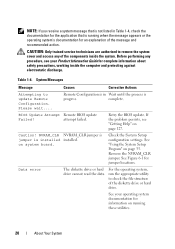
.... NVRAM_CLR NVRAM_CLR jumper is jumper is progress. See "Using the System Setup Program" on page 127. See your Product Information Guide for information on system board. complete. attempt failed. NOTE: If you receive a system message that is not listed in Wait until the process is installed installed. Before performing any of...
.... NVRAM_CLR NVRAM_CLR jumper is jumper is progress. See "Using the System Setup Program" on page 127. See your Product Information Guide for information on system board. complete. attempt failed. NOTE: If you receive a system message that is not listed in Wait until the process is installed installed. Before performing any of...

Hardware Owner's Manual (PDF)
Page 22
...failure Faulty keyboard controller See "Getting Help" on failure (faulty system board). Take the appropriate action to correct connectors. Keyboard controller Faulty keyboard controller See "Getting Help" on (faulty system board). page 127. Ensure that mouse and keyboard are securely attached to... resolve the problem. Faulty system board. If the problem persists, the system board is faulty. See "Getting Help" on page 127. ...
...failure Faulty keyboard controller See "Getting Help" on failure (faulty system board). Take the appropriate action to correct connectors. Keyboard controller Faulty keyboard controller See "Getting Help" on (faulty system board). page 127. Ensure that mouse and keyboard are securely attached to... resolve the problem. Faulty system board. If the problem persists, the system board is faulty. See "Getting Help" on page 127. ...
Hardware Owner's Manual (PDF)
Page 23
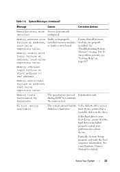
... If the diskette drive is in the drive. installed. during POST to end address Memory write/read failure at address, read value or faulty system board. boot device, ensure that all memory failure at address, installed memory modules, modules are properly read value expecting value Memory" on page 127. Memory address...
... If the diskette drive is in the drive. installed. during POST to end address Memory write/read failure at address, read value or faulty system board. boot device, ensure that all memory failure at address, installed memory modules, modules are properly read value expecting value Memory" on page 127. Memory address...
Hardware Owner's Manual (PDF)
Page 24
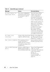
... timer tick interrupt A chip on page 113. 24 About Your System might be incorrect. If the problem persists, see "Troubleshooting Expansion Cards" on the system board Run the system diagnostics. See your Hardware Owner's Manual for reinstallation information. Not a boot diskette The operating system is Insert a diskette that all appropriate ROM...
... timer tick interrupt A chip on page 113. 24 About Your System might be incorrect. If the problem persists, see "Troubleshooting Expansion Cards" on the system board Run the system diagnostics. See your Hardware Owner's Manual for reinstallation information. Not a boot diskette The operating system is Insert a diskette that all appropriate ROM...
Hardware Owner's Manual (PDF)
Page 26
faulty system board. See particular sector on the "Troubleshooting a USB disk, or the requested sector Device" on page 111. 26 About Your System Retry Remote Configuration. configuration error ...
faulty system board. See particular sector on the "Troubleshooting a USB disk, or the requested sector Device" on page 111. 26 About Your System Retry Remote Configuration. configuration error ...
Hardware Owner's Manual (PDF)
Page 27
... 127. See "Troubleshooting System Memory" on page 127. If the problem persists, see "Getting Help" on page 108. Faulty memory module. Table 1-4. faulty stopped system board. Time-of system memory has changed the memory configuration. About Your System 27 Sector not found no disk installed. Faulty memory module. program to correct...
... 127. See "Troubleshooting System Memory" on page 127. If the problem persists, see "Getting Help" on page 108. Faulty memory module. Table 1-4. faulty stopped system board. Time-of system memory has changed the memory configuration. About Your System 27 Sector not found no disk installed. Faulty memory module. program to correct...
Hardware Owner's Manual (PDF)
Page 28
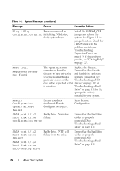
...Time-of-day not set Incorrect Time or Date - Unexpected interrupt in protected mode Faulty or improperly installed memory modules or faulty system board. If the problem persists, see "Getting Help" on page 106. If the problem persists, see "Troubleshooting System Memory" on page ...! Update the BIOS firmware. See the CDs that all memory modules are properly installed. please run SETUP settings; Timer chip counter Faulty system board. 2 failed See "Getting Help" on page 81. See "Memory Module Installation Guidelines" on page 127. No micro code update loaded for...
...Time-of-day not set Incorrect Time or Date - Unexpected interrupt in protected mode Faulty or improperly installed memory modules or faulty system board. If the problem persists, see "Getting Help" on page 106. If the problem persists, see "Troubleshooting System Memory" on page ...! Update the BIOS firmware. See the CDs that all memory modules are properly installed. please run SETUP settings; Timer chip counter Faulty system board. 2 failed See "Getting Help" on page 81. See "Memory Module Installation Guidelines" on page 127. No micro code update loaded for...
Hardware Owner's Manual (PDF)
Page 30
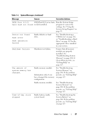
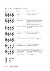
... memory modules See "Troubleshooting System detected. Memory" on page 127. See "Troubleshooting a USB Device" on page 98. Possible system board See "Troubleshooting IRQ resource and/or Assignment Conflicts" on page 102. system board If the problem persists, see "Getting hardware failure. Corrective Action See "Troubleshooting Expansion Cards" on page 108. A B C D A B C D A B C D Memory See...
... memory modules See "Troubleshooting System detected. Memory" on page 127. See "Troubleshooting a USB Device" on page 98. Possible system board See "Troubleshooting IRQ resource and/or Assignment Conflicts" on page 102. system board If the problem persists, see "Getting hardware failure. Corrective Action See "Troubleshooting Expansion Cards" on page 108. A B C D A B C D A B C D Memory See...

Hardware Owner's Manual (PDF)
Page 32
faulty system board Faulty system board. failure Main-memory refresh verification failure No memory installed Chip or data line failure in the first 64 KB ... initialization failure See "Troubleshooting System Memory" on page 114. Table 1-6. BIOS error Reflash the BIOS. Programmable interval-timer Faulty system board. See "Getting Help" failure; CMOS write/read page 108. faulty system board on page 127. System Beep Codes Code 1-1-2 1-1-3 1-1-4 1-2-1 1-2-2 1-2-3 1-3-1 1-3-2 1-3-3 1-3-4 1-4-1 1-4-2 1-4-3 1-4-4 2-1-1 through 2-4-4 Cause Corrective Action CPU register ...
faulty system board Faulty system board. failure Main-memory refresh verification failure No memory installed Chip or data line failure in the first 64 KB ... initialization failure See "Troubleshooting System Memory" on page 114. Table 1-6. BIOS error Reflash the BIOS. Programmable interval-timer Faulty system board. See "Getting Help" failure; CMOS write/read page 108. faulty system board on page 127. System Beep Codes Code 1-1-2 1-1-3 1-1-4 1-2-1 1-2-2 1-2-3 1-3-1 1-3-2 1-3-3 1-3-4 1-4-1 1-4-2 1-4-3 1-4-4 2-1-1 through 2-4-4 Cause Corrective Action CPU register ...

Hardware Owner's Manual (PDF)
Page 33
... initialization failure Screen-retrace test failure Video ROM search failure No timer tick Shutdown test failure Faulty system board. System Beep Codes (continued) Code 3-1-1 3-1-2 3-1-3 3-1-4 3-2-2 3-2-4 3-3-1 3-3-2 3-3-3 3-3-4 3-4-1 3-4-2 3-4-3 4-2-1 4-2-2 4-2-3 4-2-4 4-3-1 4-3-2 Cause Corrective Action Slave DMA-register failure Faulty system board. No memory modules installed Install a memory module in the first in protected mode See "Troubleshooting Expansion Cards" on...
... initialization failure Screen-retrace test failure Video ROM search failure No timer tick Shutdown test failure Faulty system board. System Beep Codes (continued) Code 3-1-1 3-1-2 3-1-3 3-1-4 3-2-2 3-2-4 3-3-1 3-3-2 3-3-3 3-3-4 3-4-1 3-4-2 3-4-3 4-2-1 4-2-2 4-2-3 4-2-4 4-3-1 4-3-2 Cause Corrective Action Slave DMA-register failure Faulty system board. No memory modules installed Install a memory module in the first in protected mode See "Troubleshooting Expansion Cards" on...
Hardware Owner's Manual (PDF)
Page 34
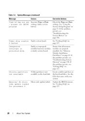
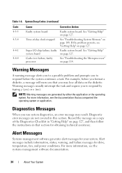
...page 127. See "Getting Help" on page 108. System Beep Codes (continued) Code 4-3-3 4-3-4 4-4-1 4-4-4 Cause Corrective Action Faulty system board Faulty system board. Time-of the Diagnostics Checklist in "Getting Help" on page 127, and then follow the instructions in this section. Record the message... on a copy of -day clock stopped See "Troubleshooting System Memory" on page 127. faulty Faulty system board. See "Getting Help" system board on the diskette. NOTE: Warning messages are not covered in that you to respond before you format a diskette, a...
...page 127. See "Getting Help" on page 108. System Beep Codes (continued) Code 4-3-3 4-3-4 4-4-1 4-4-4 Cause Corrective Action Faulty system board Faulty system board. Time-of the Diagnostics Checklist in "Getting Help" on page 127, and then follow the instructions in this section. Record the message... on a copy of -day clock stopped See "Troubleshooting System Memory" on page 127. faulty Faulty system board. See "Getting Help" system board on the diskette. NOTE: Warning messages are not covered in that you to respond before you format a diskette, a...
Hardware Owner's Manual (PDF)
Page 46
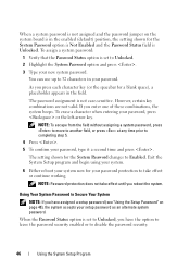
... the option to leave the password security enabled or to Enabled. As you have assigned a setup password (see "Using the Setup Password" on the system board is in your password. If you reboot the system. Exit the System Setup program and begin using your system. 6 Either reboot your system now for...
... the option to leave the password security enabled or to Enabled. As you have assigned a setup password (see "Using the Setup Password" on the system board is in your password. If you reboot the system. Exit the System Setup program and begin using your system. 6 Either reboot your system now for...

Hardware Owner's Manual (PDF)
Page 51
...; Fan assembly • Optional PCI fan • Power supply • Expansion cards • Riser card • System memory • Processor • Control panel • System board Recommended Tools You may need the following items to perform the procedures in this section: • Key to the system keylock • Wrist grounding strap...
...; Fan assembly • Optional PCI fan • Power supply • Expansion cards • Riser card • System memory • Processor • Control panel • System board Recommended Tools You may need the following items to perform the procedures in this section: • Key to the system keylock • Wrist grounding strap...
Hardware Owner's Manual (PDF)
Page 52
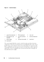
Power is supplied to two hard drives and an optional optical drive. The peripheral bays provide space for up to the system board and drives through one nonredundant power supply. 52 Installing System Components Inside the System 4 3 2 1 5 6 7 10 8 9 1 optical drive (optional) 2 ... drive 0 PCI fan (optional) 3 processor and heat 6 sink processor fan module 9 riser card memory modules (4) hard drive 1 The system board holds the system's control circuitry and other electronic components. Using a riser card, the system can accommodate two expansion cards. The processor and memory...
Power is supplied to two hard drives and an optional optical drive. The peripheral bays provide space for up to the system board and drives through one nonredundant power supply. 52 Installing System Components Inside the System 4 3 2 1 5 6 7 10 8 9 1 optical drive (optional) 2 ... drive 0 PCI fan (optional) 3 processor and heat 6 sink processor fan module 9 riser card memory modules (4) hard drive 1 The system board holds the system's control circuitry and other electronic components. Using a riser card, the system can accommodate two expansion cards. The processor and memory...

Hardware Owner's Manual (PDF)
Page 58
... battery with your Product Information Guide for complete information about safety precautions, working inside the system. See "Using the System Setup Program" on the system board. See "Removing the Riser Card" on page 79. 5 Locate the battery on page 35. 2 Open the system. NOTE: The side of the battery labeled "+" must...
... battery with your Product Information Guide for complete information about safety precautions, working inside the system. See "Using the System Setup Program" on the system board. See "Removing the Riser Card" on page 79. 5 Locate the battery on page 35. 2 Open the system. NOTE: The side of the battery labeled "+" must...


