
Information Update - Dell OpenManage™ Server Support Kit Version 4.3 (.pdf)
Page 2
...the Installation and Troubleshooting Guide for instructions. See Figure 2. not to the system's integrated NIC connector. 9 Reattach the system to the back panel instead of a screw. NOTE: Some systems use may vary on your system board and the actual expansion slot that secures the expansion-card ... See Figure 2. not to the system's integrated video connector. 8 Connect the network to the card video connector on the system. www.dell.com | support.dell.com b Insert the card-edge connector firmly into the system-board card connector until the card is fully seated. c Install the screw ...
...the Installation and Troubleshooting Guide for instructions. See Figure 2. not to the system's integrated NIC connector. 9 Reattach the system to the back panel instead of a screw. NOTE: Some systems use may vary on your system board and the actual expansion slot that secures the expansion-card ... See Figure 2. not to the system's integrated video connector. 8 Connect the network to the card video connector on the system. www.dell.com | support.dell.com b Insert the card-edge connector firmly into the system-board card connector until the card is fully seated. c Install the screw ...
Getting Started Guide
Page 6
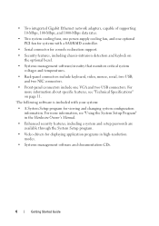
... 11. For more information, see "Technical Specifications" on the optional bezel. • Systems management software/circuitry that monitors critical system voltages and temperatures. • Back-panel connectors include keyboard, video, mouse, serial, two USB, and two NIC connectors. • Front...
... 11. For more information, see "Technical Specifications" on the optional bezel. • Systems management software/circuitry that monitors critical system voltages and temperatures. • Back-panel connectors include keyboard, video, mouse, serial, two USB, and two NIC connectors. • Front...

Hardware Owner's Manual (PDF)
Page 3
Contents 1 About Your System 11 Other Information You May Need 11 Accessing System Features During Startup 12 Front-Panel Features and Indicators 13 Back-Panel Features and Indicators 17 Connecting External Devices 18 NIC Indicator Codes 19 System Messages 19 Diagnostics Indicator Codes 29 System Beep Codes 31 Warning Messages 34 Diagnostics Messages 34 Alert Messages 34 2 Using the System Setup Program 35 Entering the System Setup Program 35 Responding to Error Messages 35 Using the System Setup Program 36 Contents 3
Contents 1 About Your System 11 Other Information You May Need 11 Accessing System Features During Startup 12 Front-Panel Features and Indicators 13 Back-Panel Features and Indicators 17 Connecting External Devices 18 NIC Indicator Codes 19 System Messages 19 Diagnostics Indicator Codes 29 System Beep Codes 31 Warning Messages 34 Diagnostics Messages 34 Alert Messages 34 2 Using the System Setup Program 35 Entering the System Setup Program 35 Responding to Error Messages 35 Using the System Setup Program 36 Contents 3

Hardware Owner's Manual (PDF)
Page 6
... Module Installation Guidelines 81 Installing Memory Modules 82 Removing Memory Modules 84 Processor 85 Replacing the Processor 85 Control Panel Assembly (Service-Only Procedure 89 Removing the Control Panel Assembly 89 Installing the Control Panel Assembly 90 System Board (Service-Only Procedure 91 Removing the System Board Assembly 91 Installing the System Board...
... Module Installation Guidelines 81 Installing Memory Modules 82 Removing Memory Modules 84 Processor 85 Replacing the Processor 85 Control Panel Assembly (Service-Only Procedure 89 Removing the Control Panel Assembly 89 Installing the Control Panel Assembly 90 System Board (Service-Only Procedure 91 Removing the System Board Assembly 91 Installing the System Board...

Hardware Owner's Manual (PDF)
Page 11
...Rack Installation Instructions included with your rack solution describe how to resolve any problems indicated by any of the following: • Front or back panel indicators • System messages • Diagnostic indicator codes • Beep codes • Warning messages • Diagnostics messages • Alert ... your system into a rack. • The Getting Started Guide provides an overview of your system's front and back panels provide convenient connectivity and system expansion capability. System conditions can be included within this section. About Your System 11
...Rack Installation Instructions included with your rack solution describe how to resolve any problems indicated by any of the following: • Front or back panel indicators • System messages • Diagnostic indicator codes • Beep codes • Warning messages • Diagnostics messages • Alert ... your system into a rack. • The Getting Started Guide provides an overview of your system's front and back panels provide convenient connectivity and system expansion capability. System conditions can be included within this section. About Your System 11
Hardware Owner's Manual (PDF)
Page 13
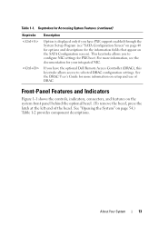
Keystrokes for Accessing System Features (continued) Keystroke Description Option is displayed only if you have the optional Dell Remote Access Controller (DRAC), this keystroke allows access to configure NIC settings for the information fields that appear on page 54.)... component descriptions. See the DRAC User's Guide for your integrated NIC. About Your System 13 If you to selected DRAC configuration settings. Front-Panel Features and Indicators Figure 1-1 shows the controls, indicators, connectors, and features on setup and use of the bezel. For more information on ...
Keystrokes for Accessing System Features (continued) Keystroke Description Option is displayed only if you have the optional Dell Remote Access Controller (DRAC), this keystroke allows access to configure NIC settings for the information fields that appear on page 54.)... component descriptions. See the DRAC User's Guide for your integrated NIC. About Your System 13 If you to selected DRAC configuration settings. Front-Panel Features and Indicators Figure 1-1 shows the controls, indicators, connectors, and features on setup and use of the bezel. For more information on ...

Hardware Owner's Manual (PDF)
Page 15
Front-Panel Components Item Component Icon 1 Power-on indicator, power button Description The power button turns system power off the system using the power button and the ...
Front-Panel Components Item Component Icon 1 Power-on indicator, power button Description The power button turns system power off the system using the power button and the ...
Hardware Owner's Manual (PDF)
Page 16
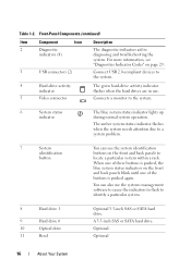
...the system needs attention due to a system problem. 7 System identification button You can also use the system identification buttons on the front and back panels to identify a particular system. 8 Hard drive 1 9 Hard drive 0 10 Optical drive 11 Bezel Optional 3.5-inch SAS or SATA hard drive... to flash to locate a particular system within a rack. For more information, see "Diagnostics Indicator Codes" on the front and back panels blink until one of the buttons is pushed, the blue system status indicators on page 29. 3 USB connectors (2) Connect USB 2.0-compliant...
...the system needs attention due to a system problem. 7 System identification button You can also use the system identification buttons on the front and back panels to identify a particular system. 8 Hard drive 1 9 Hard drive 0 10 Optical drive 11 Bezel Optional 3.5-inch SAS or SATA hard drive... to flash to locate a particular system within a rack. For more information, see "Diagnostics Indicator Codes" on the front and back panels blink until one of the buttons is pushed, the blue system status indicators on page 29. 3 USB connectors (2) Connect USB 2.0-compliant...

Hardware Owner's Manual (PDF)
Page 17
Back-Panel Features and Indicators Figure 1-2 shows the controls, indicators, and connectors located on the system's back panel. Use this button only if directed to troubleshoot software and device driver errors when using certain operating systems. This button can be pressed using the end of a paper clip. About Your System 17 Table 1-2. Front-Panel Components (continued) Item Component 12 NMI button Icon Description The NMI button is used to do so by qualified support personnel or by the operating system's documentation.
Back-Panel Features and Indicators Figure 1-2 shows the controls, indicators, and connectors located on the system's back panel. Use this button only if directed to troubleshoot software and device driver errors when using certain operating systems. This button can be pressed using the end of a paper clip. About Your System 17 Table 1-2. Front-Panel Components (continued) Item Component 12 NMI button Icon Description The NMI button is used to do so by qualified support personnel or by the operating system's documentation.

Hardware Owner's Manual (PDF)
Page 18
Figure 1-2. Back-Panel Features and Indicators 1 23 45 6 7 89 10 12 11 1 power supply connector 4 USB connectors (2) 7 video connector 10 expansion slots (2) 2 keyboard connector 3 mouse connector 5 Kensington lock 8 ...
Figure 1-2. Back-Panel Features and Indicators 1 23 45 6 7 89 10 12 11 1 power supply connector 4 USB connectors (2) 7 video connector 10 expansion slots (2) 2 keyboard connector 3 mouse connector 5 Kensington lock 8 ...

Hardware Owner's Manual (PDF)
Page 19
... 2 activity indicator Table 1-3. Link indicator is green. Next, turn on any external devices before turning on the screen to a valid link partner on the back panel has an indicator that can occur and the probable cause and corrective action for each message. • Always attach an external device while your system...
... 2 activity indicator Table 1-3. Link indicator is green. Next, turn on any external devices before turning on the screen to a valid link partner on the back panel has an indicator that can occur and the probable cause and corrective action for each message. • Always attach an external device while your system...
Hardware Owner's Manual (PDF)
Page 29
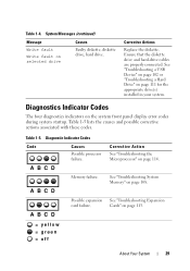
Corrective Actions Replace the diskette. See "Troubleshooting Expansion Cards" on the system front panel display error codes during system startup. Diagnostics Indicator Codes The four diagnostics indicators on page 113. = yellow = green = off About Your System 29 Ensure that ...
Corrective Actions Replace the diskette. See "Troubleshooting Expansion Cards" on the system front panel display error codes during system startup. Diagnostics Indicator Codes The four diagnostics indicators on page 113. = yellow = green = off About Your System 29 Ensure that ...

Hardware Owner's Manual (PDF)
Page 44
... restored to the last power state. AC Power Recovery (Last default) Determines how the system reacts when power is restored. On turns on the front panel. Pressing this button halts the operating system and displays a diagnostic screen. The button is enabled in the System Setup program.
... restored to the last power state. AC Power Recovery (Last default) Determines how the system reacts when power is restored. On turns on the front panel. Pressing this button halts the operating system and displays a diagnostic screen. The button is enabled in the System Setup program.

Hardware Owner's Manual (PDF)
Page 51
...; Hard drives • Fan assembly • Optional PCI fan • Power supply • Expansion cards • Riser card • System memory • Processor • Control panel • System board Recommended Tools You may need the following items to perform the procedures in this section: • Key to the system keylock •...
...; Hard drives • Fan assembly • Optional PCI fan • Power supply • Expansion cards • Riser card • System memory • Processor • Control panel • System board Recommended Tools You may need the following items to perform the procedures in this section: • Key to the system keylock •...

Hardware Owner's Manual (PDF)
Page 53
See Figure 3-2. 2 Unlatch the left end of the bezel and rotate it away from the front panel. 3 Unhook the right end of the bezel and pull the bezel away from the system. To upgrade or troubleshoot the system, remove the bezel and cover. Installing and Removing the Optional Bezel 1 2 1 key lock 2 bezel Installing System Components 53 Figure 3-2. Removing the Bezel 1 Unlock the bezel. Opening and Closing the System The system is enclosed by an optional bezel and cover.
See Figure 3-2. 2 Unlatch the left end of the bezel and rotate it away from the front panel. 3 Unhook the right end of the bezel and pull the bezel away from the system. To upgrade or troubleshoot the system, remove the bezel and cover. Installing and Removing the Optional Bezel 1 2 1 key lock 2 bezel Installing System Components 53 Figure 3-2. Removing the Bezel 1 Unlock the bezel. Opening and Closing the System The system is enclosed by an optional bezel and cover.
Hardware Owner's Manual (PDF)
Page 54
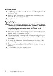
... grasp the cover on the right side of the system front plate 2 Rotate the other end of the bezel toward the front panel and press the bezel onto the panel to remove the system cover and access any of the system. Installing the Bezel 1 Hook the right end of the bezel into...
... grasp the cover on the right side of the system front plate 2 Rotate the other end of the bezel toward the front panel and press the bezel onto the panel to remove the system cover and access any of the system. Installing the Bezel 1 Hook the right end of the bezel into...
Hardware Owner's Manual (PDF)
Page 71
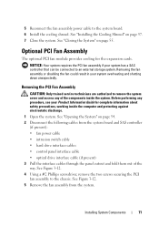
... (if present): • fan power cable • intrusion switch cable • hard drive interface cables • control panel interface cable • optical drive interface cable (if present) 3 Pull the interface cables through the panel cutout and fold them out of the components inside the computer and protecting against electrostatic discharge. 1 Open the...
... (if present): • fan power cable • intrusion switch cable • hard drive interface cables • control panel interface cable • optical drive interface cable (if present) 3 Pull the interface cables through the panel cutout and fold them out of the components inside the computer and protecting against electrostatic discharge. 1 Open the...
Hardware Owner's Manual (PDF)
Page 72
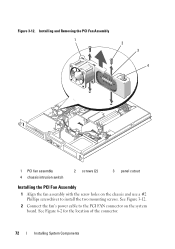
Figure 3-12. See Figure 3-12. 2 Connect the fan's power cable to the PCI FAN connector on the chassis and use a #2 Phillips screwdriver to install the two mounting screws. Installing and Removing the PCI Fan Assembly 1 2 3 4 1 PCI fan assembly 4 chassis intrusion switch 2 screws (2) 3 panel cutout Installing the PCI Fan Assembly 1 Align the fan assembly with the screw holes on the system board. See Figure 6-2 for the location of the connector. 72 Installing System Components
Figure 3-12. See Figure 3-12. 2 Connect the fan's power cable to the PCI FAN connector on the chassis and use a #2 Phillips screwdriver to install the two mounting screws. Installing and Removing the PCI Fan Assembly 1 2 3 4 1 PCI fan assembly 4 chassis intrusion switch 2 screws (2) 3 panel cutout Installing the PCI Fan Assembly 1 Align the fan assembly with the screw holes on the system board. See Figure 6-2 for the location of the connector. 72 Installing System Components

Hardware Owner's Manual (PDF)
Page 73
...controller, if present. See "Closing the System" on page 55. See "Installing a Hard Drive" on page 67. 6 Connect the control panel interface cable to the INTRUSION_SWITCH connector on the system board. See Figure 6-2 for the location of the connector. 4 Route all interface connectors through ...the panel cutout. 5 Connect the hard-drive connectors to the SATA connectors on the system board or to the chassis. See "Opening the System"...
...controller, if present. See "Closing the System" on page 55. See "Installing a Hard Drive" on page 67. 6 Connect the control panel interface cable to the INTRUSION_SWITCH connector on the system board. See Figure 6-2 for the location of the connector. 4 Route all interface connectors through ...the panel cutout. 5 Connect the hard-drive connectors to the SATA connectors on the system board or to the chassis. See "Opening the System"...

Hardware Owner's Manual (PDF)
Page 76
... card firmly into the expansion-card connector on the riser card until the card is also inserted into the securing slot on the chassis's back panel. 6 Replace the expansion-card retainer. The brackets also keep dust and dirt out of the expansion card. See Figure 3-14. 7 Slide the expansion-card sliding...
... card firmly into the expansion-card connector on the riser card until the card is also inserted into the securing slot on the chassis's back panel. 6 Replace the expansion-card retainer. The brackets also keep dust and dirt out of the expansion card. See Figure 3-14. 7 Slide the expansion-card sliding...


