
Getting Started Guide
Page 5
... hard-drive configurations: - Quad-Core Intel Xeon Processor 3200 Series. • A minimum of 512 MB of 667-MHz or 800-MHz DDR2 SDRAM memory, upgradable to two internal, 1-inch high optional Serial-Attached SCSI (SAS) hard drives with a x4 lane capability. - Up to a maximum of ...8 GB by installing combinations of 512-MB, 1-GB, or 2-GB unbuffered ECC memory modules in four memory module sockets on the system board. • One of the following processors: - One full-height, half-length, 133MHz/64 bit PCI-X expansion...
... hard-drive configurations: - Quad-Core Intel Xeon Processor 3200 Series. • A minimum of 512 MB of 667-MHz or 800-MHz DDR2 SDRAM memory, upgradable to two internal, 1-inch high optional Serial-Attached SCSI (SAS) hard drives with a x4 lane capability. - Up to a maximum of ...8 GB by installing combinations of 512-MB, 1-GB, or 2-GB unbuffered ECC memory modules in four memory module sockets on the system board. • One of the following processors: - One full-height, half-length, 133MHz/64 bit PCI-X expansion...
Getting Started Guide
Page 14
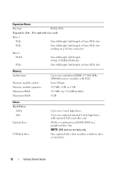
...-length, 64-bit, 133MHz PCI-X slot PCIe One full-height, half-length, x8 lane PCIe slot Memory Architecture Memory module sockets Memory module capacities Minimum RAM Maximum RAM Up to four unbuffered DDR2 677/800 MHz SDRAM memory modules with ECC Four 240-pin 512 MB, 1 GB, or 2 GB 512 MB (one 512-MB...
...-length, 64-bit, 133MHz PCI-X slot PCIe One full-height, half-length, x8 lane PCIe slot Memory Architecture Memory module sockets Memory module capacities Minimum RAM Maximum RAM Up to four unbuffered DDR2 677/800 MHz SDRAM memory modules with ECC Four 240-pin 512 MB, 1 GB, or 2 GB 512 MB (one 512-MB...
Getting Started Guide
Page 15
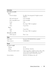
... Externally accessible Back Network adapter PS/2-style keyboard PS/2-compatible mouse Serial USB Video Front Video USB Internally accessible SATA channels Video Video type Video memory Power AC power supply Wattage Voltage Maximum inrush current System battery Two RJ-45 (for integrated 1-Gigabit network adapters) 6-pin mini-DIN 6-pin mini-DIN...
... Externally accessible Back Network adapter PS/2-style keyboard PS/2-compatible mouse Serial USB Video Front Video USB Internally accessible SATA channels Video Video type Video memory Power AC power supply Wattage Voltage Maximum inrush current System battery Two RJ-45 (for integrated 1-Gigabit network adapters) 6-pin mini-DIN 6-pin mini-DIN...

Hardware Owner's Manual (PDF)
Page 4
System Setup Options 36 Main Screen 36 Memory Information Screen 39 CPU Information Screen 39 SATA Configuration Screen 40 Integrated Devices Screen 41 Console Redirection Screen 42 System Security Screen 43 Exit Screen ...
System Setup Options 36 Main Screen 36 Memory Information Screen 39 CPU Information Screen 39 SATA Configuration Screen 40 Integrated Devices Screen 41 Console Redirection Screen 42 System Security Screen 43 Exit Screen ...

Hardware Owner's Manual (PDF)
Page 6
Riser Card 79 Removing the Riser Card 79 Installing the Riser Card 80 System Memory 81 Memory Module Installation Guidelines 81 Installing Memory Modules 82 Removing Memory Modules 84 Processor 85 Replacing the Processor 85 Control Panel Assembly (Service-Only Procedure 89 Removing the Control Panel Assembly 89 Installing the Control Panel ...
Riser Card 79 Removing the Riser Card 79 Installing the Riser Card 80 System Memory 81 Memory Module Installation Guidelines 81 Installing Memory Modules 82 Removing Memory Modules 84 Processor 85 Replacing the Processor 85 Control Panel Assembly (Service-Only Procedure 89 Removing the Control Panel Assembly 89 Installing the Control Panel ...
Hardware Owner's Manual (PDF)
Page 7
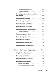
... Power Supply 106 Troubleshooting System Cooling Problems 107 Troubleshooting a Fan 108 Troubleshooting System Memory 108 Troubleshooting an Optical Drive 110 Troubleshooting a Hard Drive 111 Troubleshooting Expansion Cards 113 Troubleshooting the Microprocessor 114 5 Running the System Diagnostics . . . . . 117 Using Dell PowerEdge Diagnostics 117 System Diagnostics Features 117 When to Use the System Diagnostics 118...
... Power Supply 106 Troubleshooting System Cooling Problems 107 Troubleshooting a Fan 108 Troubleshooting System Memory 108 Troubleshooting an Optical Drive 110 Troubleshooting a Hard Drive 111 Troubleshooting Expansion Cards 113 Troubleshooting the Microprocessor 114 5 Running the System Diagnostics . . . . . 117 Using Dell PowerEdge Diagnostics 117 System Diagnostics Features 117 When to Use the System Diagnostics 118...

Hardware Owner's Manual (PDF)
Page 21
... drive. See "Troubleshooting a USB Device" on page 102 and "Troubleshooting an Optical Drive" on page 81. See "Memory Module Installation Guidelines" on page 81. Replace the diskette. Table 1-4. Diskette subsystem Faulty diskette drive or reset failed optical... drive controller. System Messages (continued) Message Causes Corrective Actions Decreasing available memory One or more memory Reinstall the memory modules might be modules and, if necessary, improperly seated or faulty. Diskette read failure Faulty or improperly...
... drive. See "Troubleshooting a USB Device" on page 102 and "Troubleshooting an Optical Drive" on page 81. See "Memory Module Installation Guidelines" on page 81. Replace the diskette. Table 1-4. Diskette subsystem Faulty diskette drive or reset failed optical... drive controller. System Messages (continued) Message Causes Corrective Actions Decreasing available memory One or more memory Reinstall the memory modules might be modules and, if necessary, improperly seated or faulty. Diskette read failure Faulty or improperly...
Hardware Owner's Manual (PDF)
Page 23
.../even logic failure at address, read failure at start address to terminate the memory test. during POST to end address Memory write/read value expecting value Memory tests terminated by keystroke The spacebar was pressed Information only. See your diskette or hard drive. System Messages (continued) Message Causes Corrective Actions Manufacturing mode ...
.../even logic failure at address, read failure at start address to terminate the memory test. during POST to end address Memory write/read value expecting value Memory tests terminated by keystroke The spacebar was pressed Information only. See your diskette or hard drive. System Messages (continued) Message Causes Corrective Actions Manufacturing mode ...
Hardware Owner's Manual (PDF)
Page 27
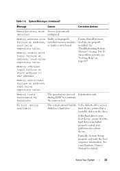
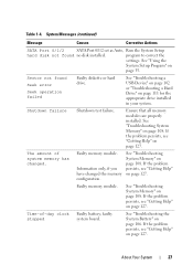
... 102 or "Troubleshooting a Hard Drive" on page 35. If the problem persists, see "Getting Help" on page 127. Faulty memory module. faulty stopped system board. About Your System 27 If the problem persists, see "Getting Help" on page 127. Time-of system...page 127. The amount of -day clock Faulty battery; If the problem persists, see "Getting Help" on page 108. Faulty memory module. Ensure that all memory modules are properly installed. System Messages (continued) Message Causes Corrective Actions SATA Port 0/1/2 SATA Port 0/1/2 set as Auto, Run...
... 102 or "Troubleshooting a Hard Drive" on page 35. If the problem persists, see "Getting Help" on page 127. Faulty memory module. faulty stopped system board. About Your System 27 If the problem persists, see "Getting Help" on page 127. Time-of system...page 127. The amount of -day clock Faulty battery; If the problem persists, see "Getting Help" on page 108. Faulty memory module. Ensure that all memory modules are properly installed. System Messages (continued) Message Causes Corrective Actions SATA Port 0/1/2 SATA Port 0/1/2 set as Auto, Run...
Hardware Owner's Manual (PDF)
Page 28
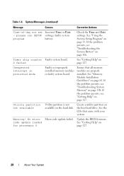
... partition not available Utility partition is not available on the hard disk Create a utility partition on page 108. See the CDs that all memory modules are properly installed. please run SETUP settings; Timer chip counter Faulty system board. 2 failed See "Getting Help" on page 127.... 28 About Your System Ensure that came with your system. See "Getting Help" on page 127. See "Memory Module Installation Guidelines" on page 127. If the problem persists, see "Troubleshooting the System Battery" on page 35. Update the BIOS firmware. System...
... partition not available Utility partition is not available on the hard disk Create a utility partition on page 108. See the CDs that all memory modules are properly installed. please run SETUP settings; Timer chip counter Faulty system board. 2 failed See "Getting Help" on page 127.... 28 About Your System Ensure that came with your system. See "Getting Help" on page 127. See "Memory Module Installation Guidelines" on page 127. If the problem persists, see "Troubleshooting the System Battery" on page 35. Update the BIOS firmware. System...
Hardware Owner's Manual (PDF)
Page 29
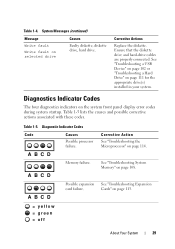
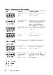
... Replace the diskette. Diagnostics Indicator Codes The four diagnostics indicators on page 111 for the appropriate drive(s) installed in your system. A B C D Memory failure. See "Troubleshooting a USB Device" on page 102 or "Troubleshooting a Hard Drive" on the system front panel display error codes during system ...drive, hard drive. Ensure that the diskette drive and hard-drive cables are properly connected. Table 1-5. Table 1-4. See "Troubleshooting System Memory" on page 113. = yellow = green = off About Your System 29 See "Troubleshooting Expansion Cards" on page 108.
... Replace the diskette. Diagnostics Indicator Codes The four diagnostics indicators on page 111 for the appropriate drive(s) installed in your system. A B C D Memory failure. See "Troubleshooting a USB Device" on page 102 or "Troubleshooting a Hard Drive" on the system front panel display error codes during system ...drive, hard drive. Ensure that the diskette drive and hard-drive cables are properly connected. Table 1-5. Table 1-4. See "Troubleshooting System Memory" on page 113. = yellow = green = off About Your System 29 See "Troubleshooting Expansion Cards" on page 108.
Hardware Owner's Manual (PDF)
Page 30
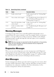
...problem persists, see "Getting hardware failure. See "Troubleshooting a USB Device" on page 127. A B C D A B C D A B C D Memory See "Troubleshooting System configuration error. A B C D System board failure. Diagnostic Indicator Codes (continued) Code Causes Possible video card failure. hard-drive are properly ...connected. A B C D No memory modules See "Troubleshooting System detected. See "Getting Help" on page 102. Possible system board See "Troubleshooting IRQ resource and/...
...problem persists, see "Getting hardware failure. See "Troubleshooting a USB Device" on page 127. A B C D A B C D A B C D Memory See "Troubleshooting System configuration error. A B C D System board failure. Diagnostic Indicator Codes (continued) Code Causes Possible video card failure. hard-drive are properly ...connected. A B C D No memory modules See "Troubleshooting System detected. See "Getting Help" on page 102. Possible system board See "Troubleshooting IRQ resource and/...

Hardware Owner's Manual (PDF)
Page 32
... write/read page 108. Programmable interval-timer Faulty system board. failure Main-memory refresh verification failure No memory installed Chip or data line failure in the first 64 KB of main memory Odd/even logic failure in the first 64 KB of main memory Address line failure in the first 64 KB of main...-safe timer test failure Software NMI port test failure Bit failure in the first 64 KB of main memory 32 About Your System See "Getting Help" failure; Table 1-6. faulty system board on DMA page register write/read failure; See "Getting Help" on page 114. ...
... write/read page 108. Programmable interval-timer Faulty system board. failure Main-memory refresh verification failure No memory installed Chip or data line failure in the first 64 KB of main memory Odd/even logic failure in the first 64 KB of main memory Address line failure in the first 64 KB of main...-safe timer test failure Software NMI port test failure Bit failure in the first 64 KB of main memory 32 About Your System See "Getting Help" failure; Table 1-6. faulty system board on DMA page register write/read failure; See "Getting Help" on page 114. ...

Hardware Owner's Manual (PDF)
Page 33
...Interrupt vector loading failure Keyboard-controller test failure CMOS failure System configuration check failure Keyboard controller not detected Video memory test failure Screen initialization failure Screen-retrace test failure Video ROM search failure No timer tick Shutdown test failure... Gate A20 failure Unexpected interrupt in the first memory module memory module connector. Improperly installed or faulty See "Troubleshooting System Memory" on page 127. See "Getting Help" on memory modules page 108. See "System connector Memory" on page 127. About Your System 33 ...
...Interrupt vector loading failure Keyboard-controller test failure CMOS failure System configuration check failure Keyboard controller not detected Video memory test failure Screen initialization failure Screen-retrace test failure Video ROM search failure No timer tick Shutdown test failure... Gate A20 failure Unexpected interrupt in the first memory module memory module connector. Improperly installed or faulty See "Troubleshooting System Memory" on page 127. See "Getting Help" on memory modules page 108. See "System connector Memory" on page 127. About Your System 33 ...
Hardware Owner's Manual (PDF)
Page 34
...: Warning messages are not covered in that accompanied the operating system or application. Record the message on a copy of -day clock stopped See "Troubleshooting System Memory" on page 127. Time-of the Diagnostics Checklist in "Getting Help" on page 127, and then follow the instructions in this section. Alert Messages Systems...
...: Warning messages are not covered in that accompanied the operating system or application. Record the message on a copy of -day clock stopped See "Troubleshooting System Memory" on page 127. Time-of the Diagnostics Checklist in "Getting Help" on page 127, and then follow the instructions in this section. Alert Messages Systems...

Hardware Owner's Manual (PDF)
Page 35
... between the installed hardware and configuration settings Entering the System Setup Program 1 Turn on page 19 for an explanation of the message. NOTE: After installing a memory upgrade, it is booting, make a note of the message and suggestions for future reference. You can enter the System Setup program by responding to send...
... between the installed hardware and configuration settings Entering the System Setup Program 1 Turn on page 19 for an explanation of the message. NOTE: After installing a memory upgrade, it is booting, make a note of the message and suggestions for future reference. You can enter the System Setup program by responding to send...
Hardware Owner's Manual (PDF)
Page 37
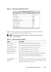
...searches the hard drives during system startup. NOTE: The System Setup program defaults are listed under their respective options, where applicable. See "Memory Information Screen" on page 40. Available options can include the diskette drive, CD drive, hard drives, and network. Figure 2-1. See ...in your system. The selections depend on the system's internal clock. System Setup Program Options Option System Time System Date Memory Information CPU Information SATA Configuration Boot Sequence Hard-Disk Drive Sequence Description Resets the time on the hard drives installed in ...
...searches the hard drives during system startup. NOTE: The System Setup program defaults are listed under their respective options, where applicable. See "Memory Information Screen" on page 40. Available options can include the diskette drive, CD drive, hard drives, and network. Figure 2-1. See ...in your system. The selections depend on the system's internal clock. System Setup Program Options Option System Time System Date Memory Information CPU Information SATA Configuration Boot Sequence Hard-Disk Drive Sequence Description Resets the time on the hard drives installed in ...
Hardware Owner's Manual (PDF)
Page 39
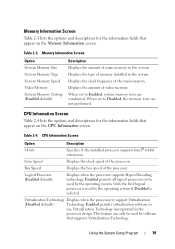
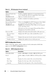
... technology. CPU Information Screen Table 2-4 lists the options and descriptions for the information fields that appear on the Memory Information screen. Bus Speed Displays the bus speed of the processor. Virtualization Technology Displays when the processor(s) support ...CPU Information screen. Table 2-3. Memory Information Screen Option System Memory Size System Memory Type System Memory Speed Video Memory System Memory Testing (Enabled default) Description Displays the amount of memory installed in the system. Displays the type of main memory in the system. Table 2-4....
... technology. CPU Information Screen Table 2-4 lists the options and descriptions for the information fields that appear on the Memory Information screen. Bus Speed Displays the bus speed of the processor. Virtualization Technology Displays when the processor(s) support ...CPU Information screen. Table 2-3. Memory Information Screen Option System Memory Size System Memory Type System Memory Speed Video Memory System Memory Testing (Enabled default) Description Displays the amount of memory installed in the system. Displays the type of main memory in the system. Table 2-4....
Hardware Owner's Manual (PDF)
Page 40
...Management (Disabled default) Processor 0 ID Processor Name Display Level 2 Cache Number of Cores Description Enables or disables optimal use of random memory access. Disable this field is read-only. If the processor does not support Demand-Based Power Management, this option for applications that...prefetcher. Displays the family and model number of the selected hard drive. 40 Using the System Setup Program Displays the number of sequential memory access. Displays the total capacity of the processor. Table 2-4. Displays the amount of the selected hard drive. Enables (Auto) or...
...Management (Disabled default) Processor 0 ID Processor Name Display Level 2 Cache Number of Cores Description Enables or disables optimal use of random memory access. Disable this field is read-only. If the processor does not support Demand-Based Power Management, this option for applications that...prefetcher. Displays the family and model number of the selected hard drive. 40 Using the System Setup Program Displays the number of sequential memory access. Displays the total capacity of the processor. Table 2-4. Displays the amount of the selected hard drive. Enables (Auto) or...

Hardware Owner's Manual (PDF)
Page 51
... battery • Optical drive • Hard drives • Fan assembly • Optional PCI fan • Power supply • Expansion cards • Riser card • System memory • Processor • Control panel • System board Recommended Tools You may need the following items to perform the procedures in this section: • Key...
... battery • Optical drive • Hard drives • Fan assembly • Optional PCI fan • Power supply • Expansion cards • Riser card • System memory • Processor • Control panel • System board Recommended Tools You may need the following items to perform the procedures in this section: • Key...


