

Glossary
Page 1
... - An information pathway between the processor and RAM. Centimeter(s). 1 A module that includes power supplies and fans. ANSI - Certificate authority. ACPI - Your system contains an expansion bus that allows the processor to direct configuration and power management. Advanced Configuration and Power Interface. CIM - Dell™ Glossary NOTE: For additional information on storage terminology, visit the Storage...
... - An information pathway between the processor and RAM. Centimeter(s). 1 A module that includes power supplies and fans. ANSI - Certificate authority. ACPI - Your system contains an expansion bus that allows the processor to direct configuration and power management. Advanced Configuration and Power Interface. CIM - Dell™ Glossary NOTE: For additional information on storage terminology, visit the Storage...

Glossary
Page 8
... to I/O devices. Symmetric multiprocessing. striping - See RAM. System Setup program - A BIOS-based program that automatically supplies power to prevent reflections and spurious signals in effect until you may use several stripes on each processor has equal access to...to remotely monitor and manage workstations. system configuration information - TCP/IP offload engine. An unregistered (unbuffered) DDR3 memory module. Uninterruptible power supply. SNMP - VGA and SVGA are connected in the configuration software for peripherals, and various ROM chips. uplink port - UPS - ...
... to I/O devices. Symmetric multiprocessing. striping - See RAM. System Setup program - A BIOS-based program that automatically supplies power to prevent reflections and spurious signals in effect until you may use several stripes on each processor has equal access to...to remotely monitor and manage workstations. system configuration information - TCP/IP offload engine. An unregistered (unbuffered) DDR3 memory module. Uninterruptible power supply. SNMP - VGA and SVGA are connected in the configuration software for peripherals, and various ROM chips. uplink port - UPS - ...

Glossary
Page 48
Super video graphics array VGA と SVGA TCP/IP - Volt VAC - Watt WH - Windows Management Instrumentation。CIM ZIF - Uninterruptible power supply USB - TCP/IP U-DIMM - Video graphics array VGA と SVGA W - Transmission Control Protocol/Internet Protocol TOE - Self-Monitoring Analysis and Reporting Technology BIOS SMP - Simple ...
Super video graphics array VGA と SVGA TCP/IP - Volt VAC - Watt WH - Windows Management Instrumentation。CIM ZIF - Uninterruptible power supply USB - TCP/IP U-DIMM - Video graphics array VGA と SVGA W - Transmission Control Protocol/Internet Protocol TOE - Self-Monitoring Analysis and Reporting Technology BIOS SMP - Simple ...

Glossary
Page 58
... provider CIM management station managed system) 은 Dell OpenManage™ Server Administrator x x y x z 58 SVGA Super Video Graphics Array VGA 와 SVGA TCP/IP Transmission Control Protocol/Internet Protocol TOE - TCP/IP TCP/IP Offload Engine U-DIMM DDR3 Unregistered(Unbuffered) DDR3 Memory Module UPS Uninterruptible Power Supply USB Universal Serial Bus USB USB USB...
... provider CIM management station managed system) 은 Dell OpenManage™ Server Administrator x x y x z 58 SVGA Super Video Graphics Array VGA 와 SVGA TCP/IP Transmission Control Protocol/Internet Protocol TOE - TCP/IP TCP/IP Offload Engine U-DIMM DDR3 Unregistered(Unbuffered) DDR3 Memory Module UPS Uninterruptible Power Supply USB Universal Serial Bus USB USB USB...

Information Update - Power Infrastructure Sizing
Page 1
... predictability for sizing the infrastructure. Systems characterized while using the power capping features enabled from Dell may result in 500W of the power supply power rating. When deploying 20 of Power Distribution Units (PDUs), Uninterruptible Power Supplies (UPSs), and other power infrastructure distribution equipment. June 2009 Using PDUs with power capping can be used , the total load would be sized...
... predictability for sizing the infrastructure. Systems characterized while using the power capping features enabled from Dell may result in 500W of the power supply power rating. When deploying 20 of Power Distribution Units (PDUs), Uninterruptible Power Supplies (UPSs), and other power infrastructure distribution equipment. June 2009 Using PDUs with power capping can be used , the total load would be sized...
Rack Installation Guide
Page 20
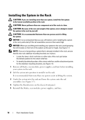
... than one person assist in the rack, avoid grasping the LCD module on the chassis front panel. 5 Reinstall the blades, rear modules, power supplies, and fans. 18 Rack Installation Guide CAUTION: Because of the size and weight of the system, never attempt to install the system in the...rack. 2 Lift the system into the rack and lower the system onto the rail assemblies (see Figure 1-8. 1 Remove all blades, rear modules, power supplies, and fans before installing your system in lifting the system. NOTICE: When you are transporting a system that more than one person assist in the...
... than one person assist in the rack, avoid grasping the LCD module on the chassis front panel. 5 Reinstall the blades, rear modules, power supplies, and fans. 18 Rack Installation Guide CAUTION: Because of the size and weight of the system, never attempt to install the system in the...rack. 2 Lift the system into the rack and lower the system onto the rail assemblies (see Figure 1-8. 1 Remove all blades, rear modules, power supplies, and fans before installing your system in lifting the system. NOTICE: When you are transporting a system that more than one person assist in the...
Getting Started Guide
Page 7
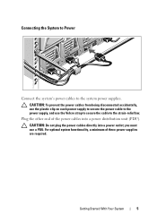
... bar. CAUTION: Do not plug the power cables directly into a power distribution unit (PDU). CAUTION: To prevent the power cables from being disconnected accidentally, use the plastic clip on each power supply to secure the power cable to the system power supplies. For optimal system functionality, a minimum of the power cables into a power outlet; Getting Started With Your System 5 Plug...
... bar. CAUTION: Do not plug the power cables directly into a power distribution unit (PDU). CAUTION: To prevent the power cables from being disconnected accidentally, use the plastic clip on each power supply to secure the power cable to the system power supplies. For optimal system functionality, a minimum of the power cables into a power outlet; Getting Started With Your System 5 Plug...
Getting Started Guide
Page 8
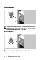
Turning On the Blades Press the power button on each blade, or power on your system. The power indicator should light. NOTE: Once you have connected the system to the power supplies, there may be a minimal delay before you can turn on the blades using the systems management software. 6 Getting Started With Your System Turning On the System Press the power button on the enclosure.
Turning On the Blades Press the power button on each blade, or power on your system. The power indicator should light. NOTE: Once you have connected the system to the power supplies, there may be a minimal delay before you can turn on the blades using the systems management software. 6 Getting Started With Your System Turning On the System Press the power button on the enclosure.
Getting Started Guide
Page 20
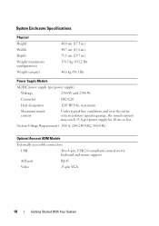
... configuration) Weight (empty) 44.0 cm (17.3 in) 44.7 cm (17.6 in) 75.5 cm (29.7 in) 178.3 kg (392.2 lb) 44.6 kg (98.1 lb) Power Supply Module AC/DC power supply (per power supply for keyboard and mouse support ACI port RJ-45 Video 15-pin VGA 18 Getting Started With Your System maximum Maximum inrush current... Under typical line conditions and over the entire system ambient operating range, the inrush current may reach 55 A per power supply) Wattage 2360 W and 2700 W Connector IEC C20 Heat dissipation 1205 BTU/hr.
... configuration) Weight (empty) 44.0 cm (17.3 in) 44.7 cm (17.6 in) 75.5 cm (29.7 in) 178.3 kg (392.2 lb) 44.6 kg (98.1 lb) Power Supply Module AC/DC power supply (per power supply for keyboard and mouse support ACI port RJ-45 Video 15-pin VGA 18 Getting Started With Your System maximum Maximum inrush current... Under typical line conditions and over the entire system ambient operating range, the inrush current may reach 55 A per power supply) Wattage 2360 W and 2700 W Connector IEC C20 Heat dissipation 1205 BTU/hr.
Dell PowerEdge M1000e Configuration Guide
Page 7
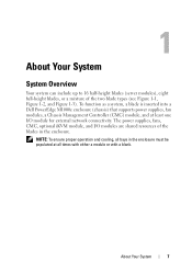
..., CMC, optional iKVM module, and I /O module for external network connectivity. About Your System 7 To function as a system, a blade is inserted into a Dell PowerEdge M1000e enclosure (chassis) that supports power supplies, fan modules, a Chassis Management Controller (CMC) module, and at all bays in the enclosure. NOTE: To ensure proper operation and cooling, all times with either...
..., CMC, optional iKVM module, and I /O module for external network connectivity. About Your System 7 To function as a system, a blade is inserted into a Dell PowerEdge M1000e enclosure (chassis) that supports power supplies, fan modules, a Chassis Management Controller (CMC) module, and at all bays in the enclosure. NOTE: To ensure proper operation and cooling, all times with either...
Dell PowerEdge M1000e Configuration Guide
Page 14
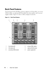
Figure 1-6 shows a fully configured enclosure. Back Panel Features 1 2 3 4 5 6 1 fan modules (9) 3 I /O modules, one or two CMC modules, an optional iKVM module, nine fan modules, and six power supply modules. Figure 1-6. Back-Panel Features The back panel of the M1000e enclosure supports six I /O modules (6) 5 secondary CMC module 2 primary CMC module 4 optional iKVM module 6 power supplies (6) 14 About Your System
Figure 1-6 shows a fully configured enclosure. Back Panel Features 1 2 3 4 5 6 1 fan modules (9) 3 I /O modules, one or two CMC modules, an optional iKVM module, nine fan modules, and six power supply modules. Figure 1-6. Back-Panel Features The back panel of the M1000e enclosure supports six I /O modules (6) 5 secondary CMC module 2 primary CMC module 4 optional iKVM module 6 power supplies (6) 14 About Your System
Dell PowerEdge M1000e Configuration Guide
Page 27
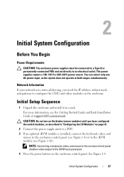
...keyboard, video, and mouse to the enclosure front panel disables video output to the iKVM back panel port. 4 Press the power button on page 47. 2 Connect the power supply units to a PDU. 3 If an optional iKVM module is installed, connect the keyboard, video, and mouse to the enclosure... addressing, you have configured the switch modules, as the system does not operate at support.dell.com/manuals. 2 Initial System Configuration Before You Begin Power Requirements CAUTION: The enclosure power supplies must be connected to a Type B or permanently-connected PDU and not directly to configure ...
...keyboard, video, and mouse to the enclosure front panel disables video output to the iKVM back panel port. 4 Press the power button on page 47. 2 Connect the power supply units to a PDU. 3 If an optional iKVM module is installed, connect the keyboard, video, and mouse to the enclosure... addressing, you have configured the switch modules, as the system does not operate at support.dell.com/manuals. 2 Initial System Configuration Before You Begin Power Requirements CAUTION: The enclosure power supplies must be connected to a Type B or permanently-connected PDU and not directly to configure ...

Hardware Owner's Manual
Page 3
... the LCD Module Menus 19 Blade Features 22 Using USB Diskette or USB DVD/CD Drives . . . . 30 Hard-Drive Features 30 Back-Panel Features 33 Power Supply Indicator 35 Fan Module Indicators 36 iKVM Module 37 Tiering the Avocent iKVM Switch From an Analog KVM Switch 40 Tiering the Avocent iKVM Switch...
... the LCD Module Menus 19 Blade Features 22 Using USB Diskette or USB DVD/CD Drives . . . . 30 Hard-Drive Features 30 Back-Panel Features 33 Power Supply Indicator 35 Fan Module Indicators 36 iKVM Module 37 Tiering the Avocent iKVM Switch From an Analog KVM Switch 40 Tiering the Avocent iKVM Switch...
Hardware Owner's Manual
Page 8
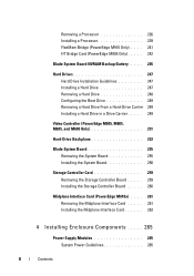
...Hard Drive From a Hard-Drive Carrier 249 Installing a Hard Drive in a Drive Carrier . . . . . 249 Video Controller (PowerEdge M905, M805, M605, and M600 Only 251 Hard-Drive Backplane 253 Blade System Board 255 Removing the System Board 255 Installing the ... Board . . . . . 259 Installing the Storage Controller Board . . . . . 260 Midplane Interface Card (PowerEdge M610x) . . . . 261 Removing the Midplane Interface Card . . . . . 261 Installing the Midplane Interface Card 263 4 Installing Enclosure Components . . . . . 265 Power Supply Modules 265 System Power Guidelines 265 8 Contents
...Hard Drive From a Hard-Drive Carrier 249 Installing a Hard Drive in a Drive Carrier . . . . . 249 Video Controller (PowerEdge M905, M805, M605, and M600 Only 251 Hard-Drive Backplane 253 Blade System Board 255 Removing the System Board 255 Installing the ... Board . . . . . 259 Installing the Storage Controller Board . . . . . 260 Midplane Interface Card (PowerEdge M610x) . . . . 261 Removing the Midplane Interface Card . . . . . 261 Installing the Midplane Interface Card 263 4 Installing Enclosure Components . . . . . 265 Power Supply Modules 265 System Power Guidelines 265 8 Contents
Hardware Owner's Manual
Page 9
Power Supply Blanks 266 Removing a Power Supply Module 266 Installing a Power Supply Module 269 Fan Modules 269 Removing a Fan Module 269 Installing a Fan Module 270 CMC Module 271 Removing a CMC Module 271 Installing an SD Card in ...
Power Supply Blanks 266 Removing a Power Supply Module 266 Installing a Power Supply Module 269 Fan Modules 269 Removing a Fan Module 269 Installing a Fan Module 270 CMC Module 271 Removing a CMC Module 271 Installing an SD Card in ...
Hardware Owner's Manual
Page 10
... 289 Troubleshooting USB Devices 290 Responding to a Systems Management Alert Message 290 Troubleshooting a Wet Enclosure 290 Troubleshooting a Damaged Enclosure 291 Troubleshooting Enclosure Components 292 Troubleshooting Power Supply Modules . . . . . 292 Troubleshooting Fan Modules 293 Troubleshooting the CMC Module 293 Troubleshooting the iKVM Module 295 Troubleshooting a Network Switch Module . . . 296 Troubleshooting Blade Components 297...
... 289 Troubleshooting USB Devices 290 Responding to a Systems Management Alert Message 290 Troubleshooting a Wet Enclosure 290 Troubleshooting a Damaged Enclosure 291 Troubleshooting Enclosure Components 292 Troubleshooting Power Supply Modules . . . . . 292 Troubleshooting Fan Modules 293 Troubleshooting the CMC Module 293 Troubleshooting the iKVM Module 295 Troubleshooting a Network Switch Module . . . 296 Troubleshooting Blade Components 297...
Hardware Owner's Manual
Page 14
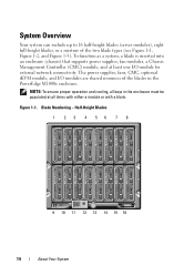
Figure 1-1. Blade Numbering - To function as a system, a blade is inserted into an enclosure (chassis) that supports power supplies, fan modules, a Chassis Management Controller (CMC) module, and at all bays in the PowerEdge M1000e enclosure. NOTE: To ensure proper operation and cooling, all times with either a module or with a blank. System Overview... (see Figure 1-1, Figure 1-2, and Figure 1-3). Half-Height Blades 1 2 3 4 56 7 8 9 10 11 12 13 14 15 16 14 About Your System The power supplies, fans, CMC, optional iKVM module, and I /O module for external network connectivity.
Figure 1-1. Blade Numbering - To function as a system, a blade is inserted into an enclosure (chassis) that supports power supplies, fan modules, a Chassis Management Controller (CMC) module, and at all bays in the PowerEdge M1000e enclosure. NOTE: To ensure proper operation and cooling, all times with either a module or with a blank. System Overview... (see Figure 1-1, Figure 1-2, and Figure 1-3). Half-Height Blades 1 2 3 4 56 7 8 9 10 11 12 13 14 15 16 14 About Your System The power supplies, fans, CMC, optional iKVM module, and I /O module for external network connectivity.

Hardware Owner's Manual
Page 19
...; Status information screens for the modules installed in the back of the enclosure, including the IO modules, fans, CMC, iKVM, and power supplies. • A network summary screen listing the IP addresses of the modules in the system. • Real time... power consumption statistics, including high and low values, and average power consumption. • Ambient temperature values. • AC power information • Critical failure alerts and warnings. LCD Module Features The primary function of the ...
...; Status information screens for the modules installed in the back of the enclosure, including the IO modules, fans, CMC, iKVM, and power supplies. • A network summary screen listing the IP addresses of the modules in the system. • Real time... power consumption statistics, including high and low values, and average power consumption. • Ambient temperature values. • AC power information • Critical failure alerts and warnings. LCD Module Features The primary function of the ...
Hardware Owner's Manual
Page 35
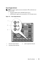
Power Supply Indicator NOTE: The power supplies must be connected to a PDU, not directly to an electrical outlet. • The power supplies require a 200-240 V power source. • A 2700 W power supply can be connected to a 110 V AC power source. Figure 1-16. Power Supply Indicators 1 2 3 1 DC power output indicator 3 AC power present indicator 2 power supply fault indicator About Your System 35
Power Supply Indicator NOTE: The power supplies must be connected to a PDU, not directly to an electrical outlet. • The power supplies require a 200-240 V power source. • A 2700 W power supply can be connected to a 110 V AC power source. Figure 1-16. Power Supply Indicators 1 2 3 1 DC power output indicator 3 AC power present indicator 2 power supply fault indicator About Your System 35
Hardware Owner's Manual
Page 36
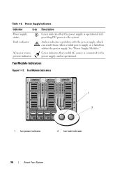
... providing DC power to the power supply and is connected to the system. See "Power Supply Modules." Fan Module Indicators Figure 1-17. Fan Module Indicators 1 2 1 fan power indicator 2 fan fault indicator 36 About Your System Amber indicates a problem with the power supply, which can result from either a failed power supply or a failed fan within the power supply. Power Supply Indicators Indicator Icon Power supply status Fault...
... providing DC power to the power supply and is connected to the system. See "Power Supply Modules." Fan Module Indicators Figure 1-17. Fan Module Indicators 1 2 1 fan power indicator 2 fan fault indicator 36 About Your System Amber indicates a problem with the power supply, which can result from either a failed power supply or a failed fan within the power supply. Power Supply Indicators Indicator Icon Power supply status Fault...


