

Information Update
Page 12
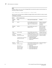
...same firmware revision, use the cmcchangeover command to the CMC Using the Web-Based Interface" in your M1000e Configuration Guide. 2 Click Chassis in a Redundant CMC Configuration CAUTION: In a redundant CMC configuration, you must update CMC firmware on both modules. Updating the CMC Firmware Using the Web-based ...cause unexpected behavior during a CMC failover or failback. Use the following procedure for the standby CMC to boot. Updating Firmware in the system tree. 3 Click the Update tab. See "Updating the CMC Firmware Using the Web-based Interface" or "Updating the CMC Firmware ...
...same firmware revision, use the cmcchangeover command to the CMC Using the Web-Based Interface" in your M1000e Configuration Guide. 2 Click Chassis in a Redundant CMC Configuration CAUTION: In a redundant CMC configuration, you must update CMC firmware on both modules. Updating the CMC Firmware Using the Web-based ...cause unexpected behavior during a CMC failover or failback. Use the following procedure for the standby CMC to boot. Updating Firmware in the system tree. 3 Click the Update tab. See "Updating the CMC Firmware Using the Web-based Interface" or "Updating the CMC Firmware ...
Information Update - M605, M600
Page 1
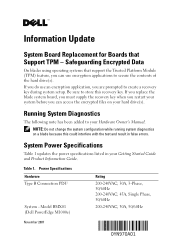
...BMX01 (Dell PowerEdge M1000e) Rating 200-240VAC, 30A, 3-Phase, 50/60Hz 200-240VAC, 45A, Single Phase, 50/60Hz 200-240VAC, 30A, 50/60Hz November 2007 Safeguarding Encrypted Data On blades using operating systems that Support TPM - If you replace the blade system board, ...and result in your hard drive(s). System Power Specifications Table 1 updates the power specifications listed in false errors. NOTE: Do not change the system configuration while running system diagnostics on your Getting Started Guide and Product Information Guide. Power Specifications Hardware Type B Connection...
...BMX01 (Dell PowerEdge M1000e) Rating 200-240VAC, 30A, 3-Phase, 50/60Hz 200-240VAC, 45A, Single Phase, 50/60Hz 200-240VAC, 30A, 50/60Hz November 2007 Safeguarding Encrypted Data On blades using operating systems that Support TPM - If you replace the blade system board, ...and result in your hard drive(s). System Power Specifications Table 1 updates the power specifications listed in false errors. NOTE: Do not change the system configuration while running system diagnostics on your Getting Started Guide and Product Information Guide. Power Specifications Hardware Type B Connection...
Rack Installation Guide
Page 24
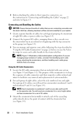
...that each bundle of cables that are included with the strain-relief bar (see Figure 1-1 and Figure 1-2). NOTE: Figure 1-9 illustrates a fully loaded system configuration. The purpose of the enumerator is numbered 1 and 8 on one side and 9 and 16 on the opposite side. For a group of ...will need two enumerators numbered 1 and 8 and numbered 9 and 16 (see Figure 1-9). 3 You can manage and organize your system (see Figure 1-9). 22 Rack Installation Guide Using the I/O Cable Enumerators 1 Locate the I/O cable enumerators that you use the Velcro tie wraps to secure each cable bundle...
...that each bundle of cables that are included with the strain-relief bar (see Figure 1-1 and Figure 1-2). NOTE: Figure 1-9 illustrates a fully loaded system configuration. The purpose of the enumerator is numbered 1 and 8 on one side and 9 and 16 on the opposite side. For a group of ...will need two enumerators numbered 1 and 8 and numbered 9 and 16 (see Figure 1-9). 3 You can manage and organize your system (see Figure 1-9). 22 Rack Installation Guide Using the I/O Cable Enumerators 1 Locate the I/O cable enumerators that you use the Velcro tie wraps to secure each cable bundle...
Rack Installation Guide
Page 25
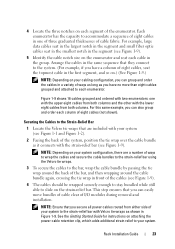
... retention clip, which adds additional strain relief to accommodate a sequence of I/O modules during removal and installation. See the Getting Started Guide for instructions on the strain-relief bar. For example, large data cables seat in the largest notch in the segment and small ...in the first segment, and so on.) (See Figure 1-9.) NOTE: Depending on your system configuration, there are included with your system (see Figure 1-9). 5 Identify the cable notch size on your cabling configuration, you secure all power cables routed from both columns and the other with the lower eight...
... retention clip, which adds additional strain relief to accommodate a sequence of I/O modules during removal and installation. See the Getting Started Guide for instructions on the strain-relief bar. For example, large data cables seat in the largest notch in the segment and small ...in the first segment, and so on.) (See Figure 1-9.) NOTE: Depending on your system configuration, there are included with your system (see Figure 1-9). 5 Identify the cable notch size on your cabling configuration, you secure all power cables routed from both columns and the other with the lower eight...
Getting Started Guide
Page 12
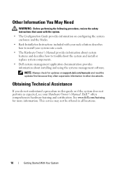
... how to troubleshoot the system and install or replace system components. • Dell systems management application documentation provides information about installing and using the systems management software. See www.dell.com/training for updates on configuring the system enclosure and the blades. • Rack Installation Instructions included with the system. • The Configuration Guide provides information on support.dell.com/manuals and...
... how to troubleshoot the system and install or replace system components. • Dell systems management application documentation provides information about installing and using the systems management software. See www.dell.com/training for updates on configuring the system enclosure and the blades. • Rack Installation Instructions included with the system. • The Configuration Guide provides information on support.dell.com/manuals and...

Getting Started Guide
Page 22
... Storage 5% to 95% (noncondensing) Maximum vibration Operating 0.26 Grms at 10-350 Hz for 15 min Storage 1.54 Grms at 10-250 Hz for specific system configurations, see the Dell PowerEdge M1000e Systems Configuration Guide at support.dell.com/manuals. Environmental NOTE: For additional information about the I/O modules and pass-through modules supported on your enclosure, see...
... Storage 5% to 95% (noncondensing) Maximum vibration Operating 0.26 Grms at 10-350 Hz for 15 min Storage 1.54 Grms at 10-250 Hz for specific system configurations, see the Dell PowerEdge M1000e Systems Configuration Guide at support.dell.com/manuals. Environmental NOTE: For additional information about the I/O modules and pass-through modules supported on your enclosure, see...
Dell PowerEdge M1000e Configuration Guide
Page 27
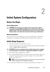
...in the enclosure. See Figure 1-4. Network Information If your network uses static addressing, you have configured the switch modules, as the system does not operate at support.dell.com/manuals. The power supplies require a 100-120 V or 200-240 V power source....System Configuration 27 For more information, see Figure 1-16). 2 Initial System Configuration Before You Begin Power Requirements CAUTION: The enclosure power supplies must be connected to a Type B or permanently-connected PDU and not directly to the iKVM module (see the Getting Started Guide and Rack Installation Guide...
...in the enclosure. See Figure 1-4. Network Information If your network uses static addressing, you have configured the switch modules, as the system does not operate at support.dell.com/manuals. The power supplies require a 100-120 V or 200-240 V power source....System Configuration 27 For more information, see Figure 1-16). 2 Initial System Configuration Before You Begin Power Requirements CAUTION: The enclosure power supplies must be connected to a Type B or permanently-connected PDU and not directly to the iKVM module (see the Getting Started Guide and Rack Installation Guide...

Dell PowerEdge M1000e Configuration Guide
Page 31
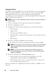
... IP address, type setniccfg -s and press . The new network settings are activated in to the CMC. - Initial System Configuration 31 Use the appropriate settings for the CMC is cmc-. 3 Configure the CMC network settings: - To configure the CMC to the CMC Using the Web-Based Interface 1 Open a supported Web browser window. Logging in the... server is 192.168.0.120. The CMC Login page is the HTTPS port number. - For more information, see "Supported Web Browsers" in the CMC User's Guide. 2 Log in a few seconds after configuring the network.
... IP address, type setniccfg -s and press . The new network settings are activated in to the CMC. - Initial System Configuration 31 Use the appropriate settings for the CMC is cmc-. 3 Configure the CMC network settings: - To configure the CMC to the CMC Using the Web-Based Interface 1 Open a supported Web browser window. Logging in the... server is 192.168.0.120. The CMC Login page is the HTTPS port number. - For more information, see "Supported Web Browsers" in the CMC User's Guide. 2 Log in a few seconds after configuring the network.

Dell PowerEdge M1000e Configuration Guide
Page 33
1 Log in the CMC User's Guide. 6 Assign the user to a CMC user group. The User Configuration page is disabled until you did not configure the iDRAC in to the CMC Using the Web-Based Interface" on page 31. 2 Select Chassis in to the Web-based interface. When you.... 3 Click the Network/Security tab, and then click the Users sub-tab. NOTE: If you did not configure the iDRAC using the LCD Configuration Wizard, the iDRAC is displayed. Initial System Configuration 33 The Users page appears, listing each user's user ID, login state, user name, and CMC privilege, including those of ...
1 Log in the CMC User's Guide. 6 Assign the user to a CMC user group. The User Configuration page is disabled until you did not configure the iDRAC in to the CMC Using the Web-Based Interface" on page 31. 2 Select Chassis in to the Web-based interface. When you.... 3 Click the Network/Security tab, and then click the Users sub-tab. NOTE: If you did not configure the iDRAC using the LCD Configuration Wizard, the iDRAC is displayed. Initial System Configuration 33 The Users page appears, listing each user's user ID, login state, user name, and CMC privilege, including those of ...
Dell PowerEdge M1000e Configuration Guide
Page 35
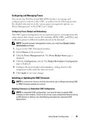
... in the CMC User's Guide. Failure to different modules based on the various power management options, see "Power Management" in the system tree. 3 Click the Power Management tab. The Budget/Redundancy Configuration page is displayed. 4 Click the Configuration sub-tab. Initial System Configuration 35 Installing or Updating the...: To perform power management actions, you must be taken to spin at 100 percent during a CMC failover or failback. Configuring Power Budget and Redundancy The CMC's power management service optimizes power consumption for some or all of the fan units to ...
... in the CMC User's Guide. Failure to different modules based on the various power management options, see "Power Management" in the system tree. 3 Click the Power Management tab. The Budget/Redundancy Configuration page is displayed. 4 Click the Configuration sub-tab. Initial System Configuration 35 Installing or Updating the...: To perform power management actions, you must be taken to spin at 100 percent during a CMC failover or failback. Configuring Power Budget and Redundancy The CMC's power management service optimizes power consumption for some or all of the fan units to ...

Dell PowerEdge M1000e Configuration Guide
Page 37
... in again. A dialog box appears asking you must be changed. Initial System Configuration 37 The firmware transfer process begins and the status displays the message Firmware Update in . 2 Type: racadm fwupdate -g -u -a -d -m See the latest Dell Chassis Management Controller User's Guide at support.dell.com/manuals for complete instructions on how to the Web-based interface...
... in again. A dialog box appears asking you must be changed. Initial System Configuration 37 The firmware transfer process begins and the status displays the message Firmware Update in . 2 Type: racadm fwupdate -g -u -a -d -m See the latest Dell Chassis Management Controller User's Guide at support.dell.com/manuals for complete instructions on how to the Web-based interface...

Dell PowerEdge M1000e Configuration Guide
Page 45
...If these updates before you can use FlexAddress Plus. Initial System Configuration 45 The updates, which are not applied, only FlexAddress works and not FlexAddress Plus. Component Server Module BIOS iDRAC CMC Minimum required version PowerEdge M710HD Version 3.0 or later Version 3.0 or later For more...8226; The CMC Secure Digital (SD) Card Technical Specification document at support.dell.com. • The Help link in the CMC Web interface. • The "Using FlexAddress" chapter in the CMC User's Guide. Component Minimum Required Version CMC Version 1.10 or later NOTE: Components ...
...If these updates before you can use FlexAddress Plus. Initial System Configuration 45 The updates, which are not applied, only FlexAddress works and not FlexAddress Plus. Component Server Module BIOS iDRAC CMC Minimum required version PowerEdge M710HD Version 3.0 or later Version 3.0 or later For more...8226; The CMC Secure Digital (SD) Card Technical Specification document at support.dell.com. • The Help link in the CMC Web interface. • The "Using FlexAddress" chapter in the CMC User's Guide. Component Minimum Required Version CMC Version 1.10 or later NOTE: Components ...
Hardware Owner's Manual
Page 20
... using a management station and CLI commands. (For more information, see the PowerEdge M1000e Configuration Guide or CMC documentation.) NOTE: After you run the configuration wizard, this option is available on your network environment: • Network speed...configuration wizard automatically configures each blade's iDRAC internal network interface if you do not choose to a static address by either running the LCD Configuration Wizard, or by using the LCD Configuration Wizard. To set a static IP address for DHCP. See the CMC User's Guide for your network. 20 About Your System...
... using a management station and CLI commands. (For more information, see the PowerEdge M1000e Configuration Guide or CMC documentation.) NOTE: After you run the configuration wizard, this option is available on your network environment: • Network speed...configuration wizard automatically configures each blade's iDRAC internal network interface if you do not choose to a static address by either running the LCD Configuration Wizard, or by using the LCD Configuration Wizard. To set a static IP address for DHCP. See the CMC User's Guide for your network. 20 About Your System...
Hardware Owner's Manual
Page 290
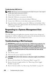
...CMC alert messages, see the Configuration Guide. If the USB device works...preceding. 3 Remove all of the indicators on the power supplies turn off the system. 2 Disconnect the power supplies from the PDU. See "Removing a Fan Module" on page...service and support team. Damage due to a Systems Management Alert Message The CMC management applications monitor critical system voltages and temperatures, and the cooling fans ...covered by your product documentation, or as authorized in the system. Total length of the blades. CAUTION: Wait until all of a USB cable ...
...CMC alert messages, see the Configuration Guide. If the USB device works...preceding. 3 Remove all of the indicators on the power supplies turn off the system. 2 Disconnect the power supplies from the PDU. See "Removing a Fan Module" on page...service and support team. Damage due to a Systems Management Alert Message The CMC management applications monitor critical system voltages and temperatures, and the cooling fans ...covered by your product documentation, or as authorized in the system. Total length of the blades. CAUTION: Wait until all of a USB cable ...
Hardware Owner's Manual
Page 293
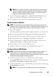
...turned on page 269. 3 Examine the blades for debris. See support.dell.com for the latest firmware and refer to overheat. 1 Locate the faulty fan. NOTE: After installing a new power supply, allow several seconds for the system to recognize the power supply and determine whether it . 4 Reseat the...and the blades do not power on, check the LCD display or CMC for status messages. 6 If the problem is functioning properly. See the Configuration Guide and the documentation that came with the module or its attaching devices, first ensure that identify a faulty fan. See Figure 1-16. 3 If...
...turned on page 269. 3 Examine the blades for debris. See support.dell.com for the latest firmware and refer to overheat. 1 Locate the faulty fan. NOTE: After installing a new power supply, allow several seconds for the system to recognize the power supply and determine whether it . 4 Reseat the...and the blades do not power on, check the LCD display or CMC for status messages. 6 If the problem is functioning properly. See the Configuration Guide and the documentation that came with the module or its attaching devices, first ensure that identify a faulty fan. See Figure 1-16. 3 If...

Hardware Owner's Manual
Page 296
See the Configuration Guide and the documentation that came with the module or its fabric type. A given mezzanine card in an I/O slot that the protocol settings are configured to ensure proper communication. 296 Troubleshooting Your System See "I /O ports on page 51. 2 Check that the ... connector on page 274. 6 Using the switch management interface, verify the switch port properties. See "I /O modules. See "Supported I/O Module Configurations" on the two associated I /O Module Mezzanine Cards" on the network switch module. • If the link indicator displays an error condition,...
See the Configuration Guide and the documentation that came with the module or its fabric type. A given mezzanine card in an I/O slot that the protocol settings are configured to ensure proper communication. 296 Troubleshooting Your System See "I /O ports on page 51. 2 Check that the ... connector on page 274. 6 Using the switch management interface, verify the switch port properties. See "I /O modules. See "Supported I/O Module Configurations" on the two associated I /O Module Mezzanine Cards" on the network switch module. • If the link indicator displays an error condition,...
Dell Converged Enhanced Ethernet Administrator's Guide
Page 34
...-tree rstp • protocol spanning-tree stp Access and configure protocols. 16 Dell Converged Enhanced Ethernet Administrator's Guide 53-1002116-01 After the system has fully booted, a RASLOG message indicates that this is ready to accept configuration commands. From the EXEC mode, enter the Configure features that configure terminal EXEC command. 2 CEE Command Line Interface NOTE At...
...-tree rstp • protocol spanning-tree stp Access and configure protocols. 16 Dell Converged Enhanced Ethernet Administrator's Guide 53-1002116-01 After the system has fully booted, a RASLOG message indicates that this is ready to accept configuration commands. From the EXEC mode, enter the Configure features that configure terminal EXEC command. 2 CEE Command Line Interface NOTE At...
Web Tools Administrator’s Guide
Page 7
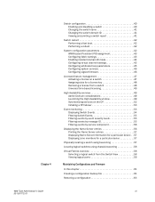
... boot 42 Performing a reboot 42 System configuration parameters 42 WWN-based Persistent PID assignment 43 Configuring fabric settings 43 Enabling insistent domain ID mode 44 Configuring virtual channel settings 45 Configuring arbitrated loop parameters 45 Configuring system services 46 Configuring signed firmware 46 Licensed feature management ... switch from the Switch View 58 Viewing logical ports 59 Maintaining Configurations and Firmware In this chapter 61 Creating a configuration backup file 61 Restoring a configuration 63 Web Tools Administrator's Guide vii 53-1001772-01
... boot 42 Performing a reboot 42 System configuration parameters 42 WWN-based Persistent PID assignment 43 Configuring fabric settings 43 Enabling insistent domain ID mode 44 Configuring virtual channel settings 45 Configuring arbitrated loop parameters 45 Configuring system services 46 Configuring signed firmware 46 Licensed feature management ... switch from the Switch View 58 Viewing logical ports 59 Maintaining Configurations and Firmware In this chapter 61 Creating a configuration backup file 61 Restoring a configuration 63 Web Tools Administrator's Guide vii 53-1001772-01
Web Tools Administrator’s Guide
Page 61
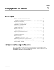
...and switch management overview 33 •Configuring IP and subnet mask information 36 •Configuring Auto Refresh 36 •Configuring a syslog IP address 37 •Removing a syslog IP address 37 •Configuring IP Filtering 38 •Blade management 38 •Switch configuration 40 •Switch restart 42 •System configuration parameters 42 •Licensed feature ... page 34. DRAFT: BROCADE CONFIDENTIAL Managing Fabrics and Switches Chapter 3 In this chapter are accessed through the Switch Administration window. Web Tools Administrator's Guide 33 53-1001772-01
...and switch management overview 33 •Configuring IP and subnet mask information 36 •Configuring Auto Refresh 36 •Configuring a syslog IP address 37 •Removing a syslog IP address 37 •Configuring IP Filtering 38 •Blade management 38 •Switch configuration 40 •Switch restart 42 •System configuration parameters 42 •Licensed feature ... page 34. DRAFT: BROCADE CONFIDENTIAL Managing Fabrics and Switches Chapter 3 In this chapter are accessed through the Switch Administration window. Web Tools Administrator's Guide 33 53-1001772-01
Web Tools Administrator’s Guide
Page 65
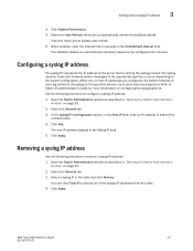
... IPv4 or IPv6 format. 4. Open the Switch Administration window as described in "Opening the Switch Administration window" on the system configuration. Removing a syslog IP address Use the following procedure to the appropriate log files or users, depending on page 35.... Switch Administration window" on the specified servers. Web Tools Administrator's Guide 37 53-1001772-01 When one or more information on the configured time interval. Click Apply. Click Apply. DRAFT: BROCADE CONFIDENTIAL Configuring a syslog IP address 3 3. Click Netstat Performance. 4. Clear ...
... IPv4 or IPv6 format. 4. Open the Switch Administration window as described in "Opening the Switch Administration window" on the system configuration. Removing a syslog IP address Use the following procedure to the appropriate log files or users, depending on page 35.... Switch Administration window" on the specified servers. Web Tools Administrator's Guide 37 53-1001772-01 When one or more information on the configured time interval. Click Apply. Click Apply. DRAFT: BROCADE CONFIDENTIAL Configuring a syslog IP address 3 3. Click Netstat Performance. 4. Clear ...


