
Getting Started Guide
Page 11
...Open the clamping ring and insert the power cable. Connecting the Power Cable(s) Connect the system's power cable(s) to the system and, if a monitor is as close as an uninterrupted power supply (UPS) or a power distribution unit (PDU). Securing the Power Cable(s) Release the latch on the ...retainer unit and pull the clamping ring towards the end of the power cables into a grounded electrical outlet or a separate power source such as possible to...
...Open the clamping ring and insert the power cable. Connecting the Power Cable(s) Connect the system's power cable(s) to the system and, if a monitor is as close as an uninterrupted power supply (UPS) or a power distribution unit (PDU). Securing the Power Cable(s) Release the latch on the ...retainer unit and pull the clamping ring towards the end of the power cables into a grounded electrical outlet or a separate power source such as possible to...

Getting Started Guide
Page 15
...Started With Your System 13 Connectors Back NIC KVM over the entire system ambient operating range, the inrush current may reach 60 A per power supply for remote management access 9-pin, DTE, 16550-compatible Two 4-pin, USB 2.0-compliant 15-pin VGA Two 4-pin, USB 2.0-compliant ...Video Video type Video memory AST2050 video controller; VGA connector 8 MB Power AC power supply (redundant and non-redundant) Wattage 650 W Voltage 115-230 VAC, 50/60 Hz, 8/4 A Heat dissipation 2217.8 BTU/hr maximum Maximum inrush...
...Started With Your System 13 Connectors Back NIC KVM over the entire system ambient operating range, the inrush current may reach 60 A per power supply for remote management access 9-pin, DTE, 16550-compatible Two 4-pin, USB 2.0-compliant 15-pin VGA Two 4-pin, USB 2.0-compliant ...Video Video type Video memory AST2050 video controller; VGA connector 8 MB Power AC power supply (redundant and non-redundant) Wattage 650 W Voltage 115-230 VAC, 50/60 Hz, 8/4 A Heat dissipation 2217.8 BTU/hr maximum Maximum inrush...

Hardware Owner's Manual
Page 6
... LAN). . . . 74 Installing the Mezzanine Card (10 GbE LAN) . . . . 76 Power Supplies 77 Removing the Non-Redundant Power Supply . . . 77 Installing the Non-Redundant Power Supply. . . . 78 Removing the Redundant Power Supply 79 Installing the Redundant Power Supply 80 Power Distribution Board 80 Removing the Power Distribution Board 80 Installing the Power Distribution Board 81 Cooling Fans 82 Removing a Cooling Fan Assembly 82...
... LAN). . . . 74 Installing the Mezzanine Card (10 GbE LAN) . . . . 76 Power Supplies 77 Removing the Non-Redundant Power Supply . . . 77 Installing the Non-Redundant Power Supply. . . . 78 Removing the Redundant Power Supply 79 Installing the Redundant Power Supply 80 Power Distribution Board 80 Removing the Power Distribution Board 80 Installing the Power Distribution Board 81 Cooling Fans 82 Removing a Cooling Fan Assembly 82...

Hardware Owner's Manual
Page 8
Troubleshooting the System Battery 100 Troubleshooting Power Supplies 101 Troubleshooting System Cooling Problems 102 Troubleshooting a Fan 102 Troubleshooting System Memory 103 Troubleshooting a Hard Drive 105 Troubleshooting a Storage Controller 106 Troubleshooting Expansion Cards 107 ... Connectors 111 Jumper Settings 112 System Configuration Jumper Settings 112 Backplane Jumper Settings 114 Backplane Connectors 115 3.5-Inch Hard Drives 115 2.5-Inch Hard Drives 116 Power Distribution Board 118 8 Contents
Troubleshooting the System Battery 100 Troubleshooting Power Supplies 101 Troubleshooting System Cooling Problems 102 Troubleshooting a Fan 102 Troubleshooting System Memory 103 Troubleshooting a Hard Drive 105 Troubleshooting a Storage Controller 106 Troubleshooting Expansion Cards 107 ... Connectors 111 Jumper Settings 112 System Configuration Jumper Settings 112 Backplane Jumper Settings 114 Backplane Connectors 115 3.5-Inch Hard Drives 115 2.5-Inch Hard Drives 116 Power Distribution Board 118 8 Contents

Hardware Owner's Manual
Page 13
... system is turned off the system using the power button causes the system to perform a graceful shutdown before power to display an image, depending on indicator lights when the system power is pushed again. The power button controls the DC power supply output to the system. Connects USB devices to... the system. About Your System 13 The power-on the amount of memory...
... system is turned off the system using the power button causes the system to perform a graceful shutdown before power to display an image, depending on indicator lights when the system power is pushed again. The power button controls the DC power supply output to the system. Connects USB devices to... the system. About Your System 13 The power-on the amount of memory...

Hardware Owner's Manual
Page 15
... Connector 4 Power-on indicator/power button 5 Fault LED Description The power-on indicator lights when the system power is turned off. NOTE: When powering on the system, the video monitor can take from several seconds to over 2 minutes to the system. Displays status/errors and is controlled by BMC. The power button controls the DC power supply output...
... Connector 4 Power-on indicator/power button 5 Fault LED Description The power-on indicator lights when the system power is turned off. NOTE: When powering on the system, the video monitor can take from several seconds to over 2 minutes to the system. Displays status/errors and is controlled by BMC. The power button controls the DC power supply output...

Hardware Owner's Manual
Page 17
.... Connects a serial device to the system. Back-Panel Features 1 2 345 6 7 8 9 10 Item Indicator, Button, or Icon Connector 1 Power supply 2 Power LED 3 Fault LED 4 System identification indicator 5 Serial connector 6 Video connector Description 650 W Lights green when the power supply is controlled by BMC. Displays status/errors and is functioning properly. Both the systems management software and...
.... Connects a serial device to the system. Back-Panel Features 1 2 345 6 7 8 9 10 Item Indicator, Button, or Icon Connector 1 Power supply 2 Power LED 3 Fault LED 4 System identification indicator 5 Serial connector 6 Video connector Description 650 W Lights green when the power supply is controlled by BMC. Displays status/errors and is functioning properly. Both the systems management software and...

Hardware Owner's Manual
Page 20
... identification off Condition IPMI using chassis identify command blink on (AC OK/DC OK) or in standby mode (90-264 VAC) Power supply faulty (UVP/OVP/OCP/SCP/OTP/Fan Fault) Power supply is off Condition System failure or Non-critical failure: non-critical fan, voltage, temperature state, or CPU thermal trip. Only IPMI...
... identification off Condition IPMI using chassis identify command blink on (AC OK/DC OK) or in standby mode (90-264 VAC) Power supply faulty (UVP/OVP/OCP/SCP/OTP/Fan Fault) Power supply is off Condition System failure or Non-critical failure: non-critical fan, voltage, temperature state, or CPU thermal trip. Only IPMI...
Hardware Owner's Manual
Page 47
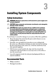
...be extremely dangerous. Recommended Tools • Phillips screwdriver • Flat-tipped screwdriver Installing System Components 47 To avoid injury to yourself or damage to a power supply can be done by the online or telephone service and support team. CAUTION: Many repairs may only be damaged by discharge of any static electricity... by the edges only. Do not touch the components on systems that is not authorized by Dell is necessary to do so. Read and follow these guidelines: • Always disconnect the system from the...
...be extremely dangerous. Recommended Tools • Phillips screwdriver • Flat-tipped screwdriver Installing System Components 47 To avoid injury to yourself or damage to a power supply can be done by the online or telephone service and support team. CAUTION: Many repairs may only be damaged by discharge of any static electricity... by the edges only. Do not touch the components on systems that is not authorized by Dell is necessary to do so. Read and follow these guidelines: • Always disconnect the system from the...

Hardware Owner's Manual
Page 48
...Dell is not covered by your product documentation, or as authorized in this section shows a system with the system cover installed to servicing that came with the product. Inside the System 5 6 4 7 3 8 2 1 9 10 1 SAS backplane 3 mezzanine card 5 cooling shroud 7 heat sink/processors (2) 9 power supply... bay(s) 2 system cooling fans (6) 4 storage controller card 6 expansion-card riser 8 memory modules (18) 10 power distribution board 48 Installing System Components Damage due to ensure proper ...
...Dell is not covered by your product documentation, or as authorized in this section shows a system with the system cover installed to servicing that came with the product. Inside the System 5 6 4 7 3 8 2 1 9 10 1 SAS backplane 3 mezzanine card 5 cooling shroud 7 heat sink/processors (2) 9 power supply... bay(s) 2 system cooling fans (6) 4 storage controller card 6 expansion-card riser 8 memory modules (18) 10 power distribution board 48 Installing System Components Damage due to ensure proper ...

Hardware Owner's Manual
Page 77
...to operate the system normally. Read and follow the safety instructions that is not authorized by Dell is not covered by the online or telephone service and support team. Power Supplies WARNING: Whenever you need to lift the system, get others to the system board and ... Figure 5-6. 4 Remove the two screws securing the power supply to the system. 5 Remove the four screws securing the bracket to the power module. 6 Lift the bracket and power supply out of injury from electric shock, disconnect the failed power supply from the AC power before removing it from the system. 3 Remove the...
...to operate the system normally. Read and follow the safety instructions that is not authorized by Dell is not covered by the online or telephone service and support team. Power Supplies WARNING: Whenever you need to lift the system, get others to the system board and ... Figure 5-6. 4 Remove the two screws securing the power supply to the system. 5 Remove the four screws securing the bracket to the power module. 6 Lift the bracket and power supply out of injury from electric shock, disconnect the failed power supply from the AC power before removing it from the system. 3 Remove the...

Hardware Owner's Manual
Page 78
... See "Closing the System" on page 54. 6 Connect the power cable to the power supply and plug the cable into the bay. Removing and Installing the Non-Redundant Power Supply 2 1 3 1 power supply 3 bracket 2 screws (6) Installing the Non-Redundant Power Supply 1 Insert the replacement power supply and the securing bracket firmly into a power outlet. 7 Reconnect your system and peripherals to the system board...
... See "Closing the System" on page 54. 6 Connect the power cable to the power supply and plug the cable into the bay. Removing and Installing the Non-Redundant Power Supply 2 1 3 1 power supply 3 bracket 2 screws (6) Installing the Non-Redundant Power Supply 1 Insert the replacement power supply and the securing bracket firmly into a power outlet. 7 Reconnect your system and peripherals to the system board...

Hardware Owner's Manual
Page 79
... the failed power supply from the AC power before removing it from the power supply. 2 Press the lever release latch on the left side of the power supply and slide out the power supply using the power supply handle. Figure 3-17. Removing the Redundant Power Supply WARNING: In order to operate the system normally. Removing and Installing the Redundant Power Supply 1 2 3 1 release latch 3 power supply 2 power supply handle Installing...
... the failed power supply from the AC power before removing it from the power supply. 2 Press the lever release latch on the left side of the power supply and slide out the power supply using the power supply handle. Figure 3-17. Removing the Redundant Power Supply WARNING: In order to operate the system normally. Removing and Installing the Redundant Power Supply 1 2 3 1 release latch 3 power supply 2 power supply handle Installing...

Hardware Owner's Manual
Page 80
.... See "Removing the Expansion-Card Riser" on the system. Installing the Redundant Power Supply 1 Verify that both power supplies are of the system. See Figure 1-4. Damage due to servicing that is not authorized by Dell is available only for the system to recognize the power supply and determine its electrical outlet. 2 Open the system. "Removing the Redundant...
.... See "Removing the Expansion-Card Riser" on the system. Installing the Redundant Power Supply 1 Verify that both power supplies are of the system. See Figure 1-4. Damage due to servicing that is not authorized by Dell is available only for the system to recognize the power supply and determine its electrical outlet. 2 Open the system. "Removing the Redundant...

Hardware Owner's Manual
Page 81
... 6 Install the cooling shroud. See "Closing the System" on page 54. 8 Reconnect the system and peripherals to the power distribution board. See "Installing the Redundant Power Supply" on page 55. 7 Replace the system cover. Installing System Components 81 Figure 3-18. See Figure 3-18. 2 Connect... the cables to their electrical outlets, and turn on page 67. 5 Install the power supplies to the system board. See "...
... 6 Install the cooling shroud. See "Closing the System" on page 54. 8 Reconnect the system and peripherals to the power distribution board. See "Installing the Redundant Power Supply" on page 55. 7 Replace the system cover. Installing System Components 81 Figure 3-18. See Figure 3-18. 2 Connect... the cables to their electrical outlets, and turn on page 67. 5 Install the power supplies to the system board. See "...

Hardware Owner's Manual
Page 99
Damage due to servicing that is not authorized by Dell is not covered by the online or telephone service and support team. See "Opening the System" on page 47. • Cooling shroud • Hard drives • Backplane • Expansion-card riser • Power supplies • Fans • Processors and heat sinks • Memory modules...
Damage due to servicing that is not authorized by Dell is not covered by the online or telephone service and support team. See "Opening the System" on page 47. • Cooling shroud • Hard drives • Backplane • Expansion-card riser • Power supplies • Fans • Processors and heat sinks • Memory modules...

Hardware Owner's Manual
Page 100
... to servicing that is not authorized by Dell is caused by the online or telephone service and support team. This situation is not covered by a certified service technician. Read and follow the safety instructions that all cables are properly installed: • Expansion-card riser • Power supplies • Fans • Hard drives •...
... to servicing that is not authorized by Dell is caused by the online or telephone service and support team. This situation is not covered by a certified service technician. Read and follow the safety instructions that all cables are properly installed: • Expansion-card riser • Power supplies • Fans • Hard drives •...

Hardware Owner's Manual
Page 101
... or telephone service and support team. CAUTION: Many repairs may be caused by software rather than by the power supply's fault indicator. Read and follow the safety instructions that the power supply is not resolved by Dell is working properly. See "Installing the System Battery" on page 78. Operating the system with the product. See...
... or telephone service and support team. CAUTION: Many repairs may be caused by software rather than by the power supply's fault indicator. Read and follow the safety instructions that the power supply is not resolved by Dell is working properly. See "Installing the System Battery" on page 78. Operating the system with the product. See...

Hardware Owner's Manual
Page 102
Damage due to servicing that none of the following conditions exist: • System cover, cooling shroud, drive blank, power supply blank, or front or back filler panel is removed. • Ambient temperature is too high. • External airflow is obstructed. &#...only perform troubleshooting and simple repairs as authorized in your product documentation, or as directed by your product documentation, or as directed by Dell is removed or has failed. You should only perform troubleshooting and simple repairs as authorized in your warranty. Troubleshooting a Fan CAUTION: Many...
Damage due to servicing that none of the following conditions exist: • System cover, cooling shroud, drive blank, power supply blank, or front or back filler panel is removed. • Ambient temperature is too high. • External airflow is obstructed. &#...only perform troubleshooting and simple repairs as authorized in your product documentation, or as directed by your product documentation, or as directed by Dell is removed or has failed. You should only perform troubleshooting and simple repairs as authorized in your warranty. Troubleshooting a Fan CAUTION: Many...

Hardware Owner's Manual
Page 110
...event log (SEL) information for 30 to 60 seconds upon applying AC power to no longer boot. The CMOS is working, try to reset the desired settings. If the BMC is now cleared and can cause a system to the power supply, the baseboard management controller (BMC) is re-applied. Do not ...unplug the power cord. 2 Open the system chassis. Collecting System Event Log for Investigation If the front panel LED blinks for...
...event log (SEL) information for 30 to 60 seconds upon applying AC power to no longer boot. The CMOS is working, try to reset the desired settings. If the BMC is now cleared and can cause a system to the power supply, the baseboard management controller (BMC) is re-applied. Do not ...unplug the power cord. 2 Open the system chassis. Collecting System Event Log for Investigation If the front panel LED blinks for...


