Upgrade the BIOS Before Upgrading Your System (.pdf)
Page 13
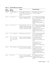
...CONNECTOR SCSI cable is faulty or improperly installed. Installation and Troubleshooting Guide. Information Update 11 See "Troubleshooting SCSI Hard Drives," "Troubleshooting a RAID Controller Card," and "Troubleshooting the Integrated RAID Controller" in your Installation and Troubleshooting ...Guide. See "Troubleshooting the Microprocessors" in your Installation and Troubleshooting Guide. See "Troubleshooting SCSI Hard Drives" in your operation. PROC MACHINE CHK Faulty or improperly installed microprocessor or system board. LCD Status Messages ...
...CONNECTOR SCSI cable is faulty or improperly installed. Installation and Troubleshooting Guide. Information Update 11 See "Troubleshooting SCSI Hard Drives," "Troubleshooting a RAID Controller Card," and "Troubleshooting the Integrated RAID Controller" in your Installation and Troubleshooting ...Guide. See "Troubleshooting the Microprocessors" in your Installation and Troubleshooting Guide. See "Troubleshooting SCSI Hard Drives" in your operation. PROC MACHINE CHK Faulty or improperly installed microprocessor or system board. LCD Status Messages ...
Installation and Troubleshooting Guide (.htm)
Page 11
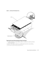
Figure 1-4. Tower-to-Rack Conversion Guide 11 Removing and Installing the Cover cover thumbscrews (2) Removing the Control Panel Assembly and Tower Front Panel 1 Label each hard drive, any optical drives, and devices installed in the media bay with their location in the chassis. 2 Remove all hard drives, media devices, and filler plates from the drive and media bays. 3 Disconnect any cables from the media bay devices.
Figure 1-4. Tower-to-Rack Conversion Guide 11 Removing and Installing the Cover cover thumbscrews (2) Removing the Control Panel Assembly and Tower Front Panel 1 Label each hard drive, any optical drives, and devices installed in the media bay with their location in the chassis. 2 Remove all hard drives, media devices, and filler plates from the drive and media bays. 3 Disconnect any cables from the media bay devices.
Installation and Troubleshooting Guide (.htm)
Page 14
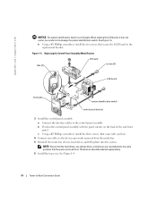
b Position the control panel assembly with your kit). 4 Connect any optical drives, and devices are reinstalled into the system. The devices should be careful not to damage the system identification switch. See Figure 1-6. h Using a #2 ... assembly: a Connect the interface cables to the devices previously removed from the media bay. 5 Reinstall the media bay devices, hard drives, and filler plates into the same positions that the hard drives, any cables to the control panel assembly. www.dell.com | support.dell.com NOTICE: The system identification switch is very fragile.
b Position the control panel assembly with your kit). 4 Connect any optical drives, and devices are reinstalled into the system. The devices should be careful not to damage the system identification switch. See Figure 1-6. h Using a #2 ... assembly: a Connect the interface cables to the devices previously removed from the media bay. 5 Reinstall the media bay devices, hard drives, and filler plates into the same positions that the hard drives, any cables to the control panel assembly. www.dell.com | support.dell.com NOTICE: The system identification switch is very fragile.


