Upgrade the BIOS Before Upgrading Your System (.pdf)
Page 5
...: • Reconfiguring the system for regional power requirements • Processor upgrades • Adaptec SCSI Card 39160 expansion-card slot restrictions • System start-up behavior • Integrated NIC IPMI port functionality • Remote Access Controller card interaction with more than eight logical processors - NIC device names • Microsoft® Windows Server™ 2003 installation with more than eight logical processors with Red Hat Enterprise Linux (Version 4) for Intel Extended Memory 64 Technology (Intel EM64T) - Before performing...
...: • Reconfiguring the system for regional power requirements • Processor upgrades • Adaptec SCSI Card 39160 expansion-card slot restrictions • System start-up behavior • Integrated NIC IPMI port functionality • Remote Access Controller card interaction with more than eight logical processors - NIC device names • Microsoft® Windows Server™ 2003 installation with more than eight logical processors with Red Hat Enterprise Linux (Version 4) for Intel Extended Memory 64 Technology (Intel EM64T) - Before performing...
Upgrade the BIOS Before Upgrading Your System (.pdf)
Page 7
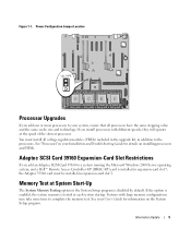
...be installed in your User's Guide for details on the System Setup program. See "Processors" in expansion-card slot 2. See your Installation and Troubleshooting Guide for information on installing processors and VRMs. Adaptec SCSI Card 39160 Expansion-Card Slot Restrictions If you add one or more time to a system running the Microsoft Windows 2000 Server operating system, and a Dell™ Remote Access Controller 4/P (DRAC 4/P) card is disabled by default. Power Configuration Jumper Location Processor Upgrades If you add an Adaptec SCSI Card 39160 to complete the memory test...
...be installed in your User's Guide for details on the System Setup program. See "Processors" in expansion-card slot 2. See your Installation and Troubleshooting Guide for information on installing processors and VRMs. Adaptec SCSI Card 39160 Expansion-Card Slot Restrictions If you add one or more time to a system running the Microsoft Windows 2000 Server operating system, and a Dell™ Remote Access Controller 4/P (DRAC 4/P) card is disabled by default. Power Configuration Jumper Location Processor Upgrades If you add an Adaptec SCSI Card 39160 to complete the memory test...
Upgrade the BIOS Before Upgrading Your System (.pdf)
Page 8
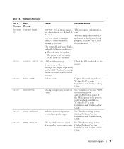
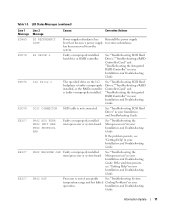
Remote Access Controller Card Interaction With Integrated Video If you configure the NIC to support IPMI management traffic, the NIC driver's Large-Send Offload (LSO) feature will be disabled. System Messages Table 1-3 provides an updated list of system status messages that port. In addition, if you install an optional remote access controller card for remote systems management, the system's front and back panel video ports will not be available for management traffic during system start -up briefly and then stop. (See...
Remote Access Controller Card Interaction With Integrated Video If you configure the NIC to support IPMI management traffic, the NIC driver's Large-Send Offload (LSO) feature will be disabled. System Messages Table 1-3 provides an updated list of system status messages that port. In addition, if you install an optional remote access controller card for remote systems management, the system's front and back panel video ports will not be available for management traffic during system start -up briefly and then stop. (See...
Upgrade the BIOS Before Upgrading Your System (.pdf)
Page 9
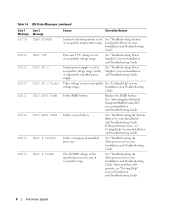
... can display sequentially on . • The power is a unique name, five characters or less, defined by the user. FAIL SAFE Failsafe event. Information Update 7 MISCONFIG Missing or improperly installed VRMs. See "Installing a Processor VRM" in your Installation and Troubleshooting Guide. Cooling Problems" in your Installation and Troubleshooting Guide. See your Installation and Troubleshooting Guide. A maximum of three error messages can change the system ID and name in your User's Guide for instructions. See "Troubleshooting System Cooling Problems...
... can display sequentially on . • The power is a unique name, five characters or less, defined by the user. FAIL SAFE Failsafe event. Information Update 7 MISCONFIG Missing or improperly installed VRMs. See "Installing a Processor VRM" in your Installation and Troubleshooting Guide. Cooling Problems" in your Installation and Troubleshooting Guide. See your Installation and Troubleshooting Guide. A maximum of three error messages can change the system ID and name in your User's Guide for instructions. See "Troubleshooting System Cooling Problems...
Upgrade the BIOS Before Upgrading Your System (.pdf)
Page 10
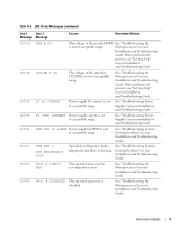
... PG n Video VOLT BATT ROMB VOLT BATT CMOS PROC # STATUS PROC # VCORE Causes Corrective Actions System board temperature is out of acceptable temperature range. System power supply is out of acceptable voltage range; Replace the RAID battery. Faulty system battery. Faulty or improperly installed processor. The VCORE voltage of the specified processor is out of acceptable range. See "Troubleshooting the Microprocessors" in your Installation and Troubleshooting Guide. 8 Information Update If the problem persists...
... PG n Video VOLT BATT ROMB VOLT BATT CMOS PROC # STATUS PROC # VCORE Causes Corrective Actions System board temperature is out of acceptable temperature range. System power supply is out of acceptable voltage range; Replace the RAID battery. Faulty system battery. Faulty or improperly installed processor. The VCORE voltage of the specified processor is out of acceptable range. See "Troubleshooting the Microprocessors" in your Installation and Troubleshooting Guide. 8 Information Update If the problem persists...
Upgrade the BIOS Before Upgrading Your System (.pdf)
Page 11
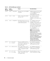
... VCACHE is disabled. See "Troubleshooting Power Supplies" in your Installation and Troubleshooting Guide. See "Troubleshooting Power Supplies" in your Installation and Troubleshooting Guide. RPM FAN PS BLANK Power supply fan RPM is faulty, improperly installed, or missing. RPM FAN n FAN REDUNDANCY LOST Specified cooling fan is out of acceptable range. PROC # CONFIG ERR The specified processor has a configuration error. See "Troubleshooting the Microprocessors" in your Installation and Troubleshooting Guide. Information Update 9 LCD Status Messages (continued...
... VCACHE is disabled. See "Troubleshooting Power Supplies" in your Installation and Troubleshooting Guide. See "Troubleshooting Power Supplies" in your Installation and Troubleshooting Guide. RPM FAN PS BLANK Power supply fan RPM is faulty, improperly installed, or missing. RPM FAN n FAN REDUNDANCY LOST Specified cooling fan is out of acceptable range. PROC # CONFIG ERR The specified processor has a configuration error. See "Troubleshooting the Microprocessors" in your Installation and Troubleshooting Guide. Information Update 9 LCD Status Messages (continued...
Upgrade the BIOS Before Upgrading Your System (.pdf)
Page 12
... the system's power cord is disconnected and reconnected to the AC power source, or the SEL is out of acceptable range. 10 Information Update See the Dell OpenManage Baseboard Management Controller User's Guide for the specified power supply. PS n PREDICTIVE Power supply voltage is cleared using either Server Assistant or the BMC Management Utility. PS n AC LOST PS n AC RANGE Power source for specified power Check the AC power source supply is improperly installed and Troubleshooting Guide.
... the system's power cord is disconnected and reconnected to the AC power source, or the SEL is out of acceptable range. 10 Information Update See the Dell OpenManage Baseboard Management Controller User's Guide for the specified power supply. PS n PREDICTIVE Power supply voltage is cleared using either Server Assistant or the BMC Management Utility. PS n AC LOST PS n AC RANGE Power source for specified power Check the AC power source supply is improperly installed and Troubleshooting Guide.
Upgrade the BIOS Before Upgrading Your System (.pdf)
Page 13
... Guide. See "Troubleshooting SCSI Hard Drives," "Troubleshooting a RAID Controller Card," and "Troubleshooting the Integrated RAID Controller" in your operation. PROC MACHINE CHK Faulty or improperly installed microprocessor or system board. See "Troubleshooting the Microprocessors" in your Installation and Troubleshooting Guide. 1x2 Drive n The specified drive on the 1x2 backplane is faulty or improperly installed, or the RAID controller is not connected. PROC BUS PERR PROC INIT ERR PROC PROTOCOL ERR Faulty or improperly installed microprocessor or system board. PROC HOT...
... Guide. See "Troubleshooting SCSI Hard Drives," "Troubleshooting a RAID Controller Card," and "Troubleshooting the Integrated RAID Controller" in your operation. PROC MACHINE CHK Faulty or improperly installed microprocessor or system board. See "Troubleshooting the Microprocessors" in your Installation and Troubleshooting Guide. 1x2 Drive n The specified drive on the 1x2 backplane is faulty or improperly installed, or the RAID controller is not connected. PROC BUS PERR PROC INIT ERR PROC PROTOCOL ERR Faulty or improperly installed microprocessor or system board. PROC HOT...
Upgrade the BIOS Before Upgrading Your System (.pdf)
Page 14
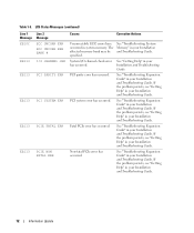
Table 1-3. LCD Status Messages (continued) Line 1 Message EB10C EB113 EB113 EB113 EB113 EB113 Line 2 Message ECC UNCORR ERR ECC UNCORR ERR BANK # I /O channel check error has occurred. See "Troubleshooting System Memory" in system memory. PCI parity error has occurred. See "Troubleshooting Expansion Cards" in your Installation and Troubleshooting Guide. If the problem persists, see "Getting Help" in your Installation and Troubleshooting Guide. System I /O CHANNEL CHK PCI PARITY ERR PCI SYSTEM ERR PCIE FATAL ERR PCIE NON...
Table 1-3. LCD Status Messages (continued) Line 1 Message EB10C EB113 EB113 EB113 EB113 EB113 Line 2 Message ECC UNCORR ERR ECC UNCORR ERR BANK # I /O channel check error has occurred. See "Troubleshooting System Memory" in system memory. PCI parity error has occurred. See "Troubleshooting Expansion Cards" in your Installation and Troubleshooting Guide. If the problem persists, see "Getting Help" in your Installation and Troubleshooting Guide. System I /O CHANNEL CHK PCI PARITY ERR PCI SYSTEM ERR PCIE FATAL ERR PCIE NON...
Upgrade the BIOS Before Upgrading Your System (.pdf)
Page 15
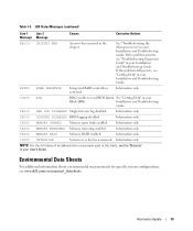
... Integrated RAID controller is activated. Information only. If the problem persists, see the "Glossary" in your Installation and Troubleshooting Guide. IB110 SBE LOG DISABLED Single-bit error log disabled. IB110 LOGGING DISABLED BIOS logging disabled. IS000 INTRUSION System cover has been removed. Information only. Information only. IB10C MEMORY MIRRORED Memory mirroring enabled. Environmental Data Sheets For additional information about environmental measurements for specific system configurations, see "Getting Help" in the chipset. LCD Status Messages...
... Integrated RAID controller is activated. Information only. If the problem persists, see the "Glossary" in your Installation and Troubleshooting Guide. IB110 SBE LOG DISABLED Single-bit error log disabled. IB110 LOGGING DISABLED BIOS logging disabled. IS000 INTRUSION System cover has been removed. Information only. Information only. IB10C MEMORY MIRRORED Memory mirroring enabled. Environmental Data Sheets For additional information about environmental measurements for specific system configurations, see "Getting Help" in the chipset. LCD Status Messages...
Upgrade the BIOS Before Upgrading Your System (.pdf)
Page 17
... Intel EM64T operating system. However, if you install a PCI-X NIC card, the card's NIC port is configured with more than eight logical processors even if more than SP1. To work around this issue will be available in the order of Microsoft Windows Server 2003 Standard or Enterprise Edition earlier than eight logical processors, the Linux operating system will cause the operating system to use the power button to the...
... Intel EM64T operating system. However, if you install a PCI-X NIC card, the card's NIC port is configured with more than eight logical processors even if more than SP1. To work around this issue will be available in the order of Microsoft Windows Server 2003 Standard or Enterprise Edition earlier than eight logical processors, the Linux operating system will cause the operating system to use the power button to the...
Upgrade the BIOS Before Upgrading Your System (.pdf)
Page 18
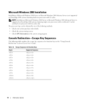
...: Installation of your system purchase order details. • Check the system startup screen. • Check CPU Information in the "Using Console Redirection" section of Microsoft Windows 2000 Server or Microsoft Windows 2000 Advanced Server is not supported on PowerEdge 6800 systems featuring single-core processors (with or without L3 cache) and dual-core processors with L3 cache. Console Redirection-Escape Key Sequences The following methods: • Check your User's Guide...
...: Installation of your system purchase order details. • Check the system startup screen. • Check CPU Information in the "Using Console Redirection" section of Microsoft Windows 2000 Server or Microsoft Windows 2000 Advanced Server is not supported on PowerEdge 6800 systems featuring single-core processors (with or without L3 cache) and dual-core processors with L3 cache. Console Redirection-Escape Key Sequences The following methods: • Check your User's Guide...

Upgrade the BIOS Before Upgrading Your System (.pdf)
Page 29
...; 2 行 信息 PCI SYSTEM ERR PCI 纠正措施 EB113 PCIE FATAL ERR PCIe 错误。 EB113 PCIE NON FATAL ERR PCIe 错误。 EB113 EFFF2 I0000 IB110 CHIPSET ERR ROMB PRESENCE RAID BIB BMC BIOS 初始块 (BIB)。 SBE LOG DISABLED IB110 IB10C IB10C LOGGING DISABLED 已禁用 BIOS MEMORY SPARED MEMORY MIRRORED IB10C MEMORY RAID RAID。 IS000 INTRUSION 仅...
...; 2 行 信息 PCI SYSTEM ERR PCI 纠正措施 EB113 PCIE FATAL ERR PCIe 错误。 EB113 PCIE NON FATAL ERR PCIe 错误。 EB113 EFFF2 I0000 IB110 CHIPSET ERR ROMB PRESENCE RAID BIB BMC BIOS 初始块 (BIB)。 SBE LOG DISABLED IB110 IB10C IB10C LOGGING DISABLED 已禁用 BIOS MEMORY SPARED MEMORY MIRRORED IB10C MEMORY RAID RAID。 IS000 INTRUSION 仅...
Dell OpenManage™ Server Support Kit Version 4.3 (.pdf)
Page 1
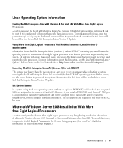
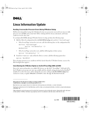
... start successfully with the default settings chosen by the Red Hat® installer. April 2005 www.dell.com | support.dell.com RC829am1.fm Page 1 Friday, April 15, 2005 2:32 PM Linux Information Update Avoiding Irrecoverable Processor Errors During X Window Startup Dell has determined that section: Option "PciOsConfig" "1" 2 Search for "ServerFlags". • If the ServerFlags section does not exist, add the following lines to the configuration...
... start successfully with the default settings chosen by the Red Hat® installer. April 2005 www.dell.com | support.dell.com RC829am1.fm Page 1 Friday, April 15, 2005 2:32 PM Linux Information Update Avoiding Irrecoverable Processor Errors During X Window Startup Dell has determined that section: Option "PciOsConfig" "1" 2 Search for "ServerFlags". • If the ServerFlags section does not exist, add the following lines to the configuration...

Installation and Troubleshooting Guide (.htm)
Page 3
... Cover 9 Removing the Control Panel Assembly and Tower Front Panel 11 Installing the Rack Front Panel and Control Panel Assembly 13 Removing the Trim Panel 15 Installing the System in a Rack 16 Installing the Optional Rack Bezel 16 Figures Figure 1-1. Figure 1-2. Figure 1-7. Figure 1-3. Figure 1-5. Figure 1-8. Figure 1-6. Tower-To-Rack Kit Contents 8 Removing the Optional Tower Bezel 9 Removing the Metal Feet 10 Removing and Installing the Cover 11 Removing and Installing the Control Panel Assembly and Front Panel 12 Replacing...
... Cover 9 Removing the Control Panel Assembly and Tower Front Panel 11 Installing the Rack Front Panel and Control Panel Assembly 13 Removing the Trim Panel 15 Installing the System in a Rack 16 Installing the Optional Rack Bezel 16 Figures Figure 1-1. Figure 1-2. Figure 1-7. Figure 1-3. Figure 1-5. Figure 1-8. Figure 1-6. Tower-To-Rack Kit Contents 8 Removing the Optional Tower Bezel 9 Removing the Metal Feet 10 Removing and Installing the Cover 11 Removing and Installing the Control Panel Assembly and Front Panel 12 Replacing...

Installation and Troubleshooting Guide (.htm)
Page 5
... have the final combination of system and rack kit in a cabinet evaluated for specific warning and/or caution statements and procedures. Due to the height and weight of the rack, it is your responsibility to other racks. Failure to install stabilizers accordingly before extending a component from the rack. • Use caution when pressing the component rail release latches and sliding a component into...
... have the final combination of system and rack kit in a cabinet evaluated for specific warning and/or caution statements and procedures. Due to the height and weight of the rack, it is your responsibility to other racks. Failure to install stabilizers accordingly before extending a component from the rack. • Use caution when pressing the component rail release latches and sliding a component into...
Installation and Troubleshooting Guide (.htm)
Page 6
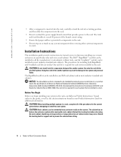
... the specifications of American National Standards Institute (ANSI)/Electronic Industries Association (EIA) standard ANSI/EIA-310-D-92, International Electrotechnical Commission (IEC) 297, and Deutsche Industrie Norm (DIN) 41494. Use extreme caution while moving the rack cabinet. Installation Instructions This installation guide provides instructions for each system that proper airflow is required for trained service technicians installing one or more systems in an open...
... the specifications of American National Standards Institute (ANSI)/Electronic Industries Association (EIA) standard ANSI/EIA-310-D-92, International Electrotechnical Commission (IEC) 297, and Deutsche Industrie Norm (DIN) 41494. Use extreme caution while moving the rack cabinet. Installation Instructions This installation guide provides instructions for each system that proper airflow is required for trained service technicians installing one or more systems in an open...
Installation and Troubleshooting Guide (.htm)
Page 11
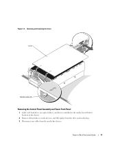
Tower-to-Rack Conversion Guide 11 Figure 1-4. Removing and Installing the Cover cover thumbscrews (2) Removing the Control Panel Assembly and Tower Front Panel 1 Label each hard drive, any optical drives, and devices installed in the media bay with their location in the chassis. 2 Remove all hard drives, media devices, and filler plates from the drive and media bays. 3 Disconnect any cables from the media bay devices.
Tower-to-Rack Conversion Guide 11 Figure 1-4. Removing and Installing the Cover cover thumbscrews (2) Removing the Control Panel Assembly and Tower Front Panel 1 Label each hard drive, any optical drives, and devices installed in the media bay with their location in the chassis. 2 Remove all hard drives, media devices, and filler plates from the drive and media bays. 3 Disconnect any cables from the media bay devices.
Installation and Troubleshooting Guide (.htm)
Page 13
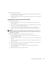
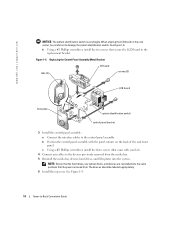
Installing the Rack Front Panel and Control Panel Assembly 1 Install the rack front panel: a Orient the system so that secures the I /O board to the replacement bracket. 5 Remove the tower front panel: a Using a T-10 Torx driver, remove the 4 flat-head screws located between the drive bays on the rack front panel. NOTE: The control panel assembly's LCD board and the I /O board on the tower front panel. See Figure 1-5. c Using a T-10 Torx driver, install the additional 4 flat-head screws (supplied in...
Installing the Rack Front Panel and Control Panel Assembly 1 Install the rack front panel: a Orient the system so that secures the I /O board to the replacement bracket. 5 Remove the tower front panel: a Using a T-10 Torx driver, remove the 4 flat-head screws located between the drive bays on the rack front panel. NOTE: The control panel assembly's LCD board and the I /O board on the tower front panel. See Figure 1-5. c Using a T-10 Torx driver, install the additional 4 flat-head screws (supplied in...
Installation and Troubleshooting Guide (.htm)
Page 14
... bay devices, hard drives, and filler plates into the same positions that they were removed from. h Using a #2 Phillips screwdriver, install the two screws that came with the panel cutouts on the rack carrier, be labeled appropriately. 6 Install the top cover. c Using a #2 Phillips screwdriver, install the three screws (that secure the LCD board to -Rack Conversion Guide See Figure 1-4. 14 Tower-to the replacement bracket. www.dell.com | support.dell...
... bay devices, hard drives, and filler plates into the same positions that they were removed from. h Using a #2 Phillips screwdriver, install the two screws that came with the panel cutouts on the rack carrier, be labeled appropriately. 6 Install the top cover. c Using a #2 Phillips screwdriver, install the three screws (that secure the LCD board to -Rack Conversion Guide See Figure 1-4. 14 Tower-to the replacement bracket. www.dell.com | support.dell...


