Microprocessor Upgrade Installation Guide
Page 3
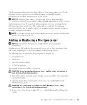
... its associated cache memory are included in your System Information document. 1 Turn off the system, including any peripherals, and disconnect the power cable from the electrical outlet. 2 Open the system doors, or remove the system cover (see your Installation and Troubleshooting Guide). In...to accommodate secondary microprocessors. CAUTION: Before you add or replace a microprocessor, check the latest system BIOS information on the Dell Support website at support.dell.com, and upgrade the BIOS if necessary. The following items are contained in a pin-grid array (PGA) package that...
... its associated cache memory are included in your System Information document. 1 Turn off the system, including any peripherals, and disconnect the power cable from the electrical outlet. 2 Open the system doors, or remove the system cover (see your Installation and Troubleshooting Guide). In...to accommodate secondary microprocessors. CAUTION: Before you add or replace a microprocessor, check the latest system BIOS information on the Dell Support website at support.dell.com, and upgrade the BIOS if necessary. The following items are contained in a pin-grid array (PGA) package that...
Rack Installation Guide
Page 123
c 3 3 3 d 3 6-32 × e 12mm (0.5 ) f 6 a ( and Troubleshooting Guide ) b supplies installed in the system ( Installation and Troubleshooting Guide c CTRL_PNL d LED e LED f 10 Torx g h i 6-32 × ¼ Installation (Remove all power ) 4 T- 12 T-10 Torx 2 4-17
c 3 3 3 d 3 6-32 × e 12mm (0.5 ) f 6 a ( and Troubleshooting Guide ) b supplies installed in the system ( Installation and Troubleshooting Guide c CTRL_PNL d LED e LED f 10 Torx g h i 6-32 × ¼ Installation (Remove all power ) 4 T- 12 T-10 Torx 2 4-17
Rack-to-Tower Conversion Guide
Page 5
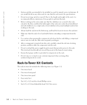
...component is level and stable before working on the floor. Install front and side stabilizers on any other systems/components in a rack. www.dell.com | support.dell.com • System rack kits are secured to the rack, extend to the floor, and that the rack meets the specifications. &#...; Use caution when pressing the component rail release latches and sliding a component into the rack. • Do not overload the power supply branch circuit that provides power to the rack. Rack-to-Tower Kit Contents The rack-to-tower kit includes the following items (see Figure 1-1): •...
...component is level and stable before working on the floor. Install front and side stabilizers on any other systems/components in a rack. www.dell.com | support.dell.com • System rack kits are secured to the rack, extend to the floor, and that the rack meets the specifications. &#...; Use caution when pressing the component rail release latches and sliding a component into the rack. • Do not overload the power supply branch circuit that provides power to the rack. Rack-to-Tower Kit Contents The rack-to-tower kit includes the following items (see Figure 1-1): •...
Rack-to-Tower Conversion Guide
Page 8
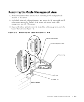
... system you are converting as well as all peripherals attached to this system. 2 At the back of the rack cabinet, disconnect and remove the AC power cable and all other cables connected to the back of the system and secured to the cablemanagement arm with Velcro straps. 3 Squeeze the release tab...
... system you are converting as well as all peripherals attached to this system. 2 At the back of the rack cabinet, disconnect and remove the AC power cable and all other cables connected to the back of the system and secured to the cablemanagement arm with Velcro straps. 3 Squeeze the release tab...
Rack-to-Tower Conversion Guide
Page 9
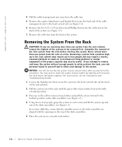
...platform or similar equipment of the proper capacity may wish to make the system chassis lighter by labeling and removing the hard drives and power supplies (for instructions, see the Installation and Troubleshooting Guide). 1 Loosen the thumbscrews that secure the system to the front vertical rails (at the... the system. Complete the removal of the first system from the rack before starting the second. NOTICE: You will be useful. www.dell.com | support.dell.com 4 Pull the cable-management arm away from the cable tray. 5 Remove the captive thumbscrew and bracket that secure the back end...
...platform or similar equipment of the proper capacity may wish to make the system chassis lighter by labeling and removing the hard drives and power supplies (for instructions, see the Installation and Troubleshooting Guide). 1 Loosen the thumbscrews that secure the system to the front vertical rails (at the... the system. Complete the removal of the first system from the rack before starting the second. NOTICE: You will be useful. www.dell.com | support.dell.com 4 Pull the cable-management arm away from the cable tray. 5 Remove the captive thumbscrew and bracket that secure the back end...
Rack-to-Tower Conversion Guide
Page 12
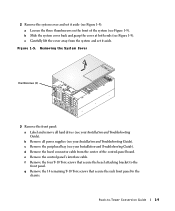
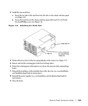
... system cover and set it aside (see your Installation and Troubleshooting Guide). Removing the System Cover thumbscrews (3) 3 Remove the front panel: a Label and remove all power supplies (see Figure 1-5). b Remove all hard drives (see Figure 1-5). Rack-to the chassis. e Remove the control panel's interface cable. b Slide the system cover back and...
... system cover and set it aside (see your Installation and Troubleshooting Guide). Removing the System Cover thumbscrews (3) 3 Remove the front panel: a Label and remove all power supplies (see Figure 1-5). b Remove all hard drives (see Figure 1-5). Rack-to the chassis. e Remove the control panel's interface cable. b Slide the system cover back and...
Rack-to-Tower Conversion Guide
Page 15
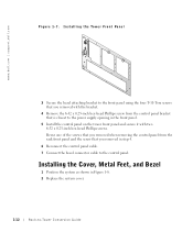
www.dell.com | support.dell.com Figure 1-7. Reuse one of the screws that is closest to the power supply opening in the front panel. 5 Install the control panel on the tower front panel and secure it with the bracket. 4 Remove the 6-32 x 0.25-...
www.dell.com | support.dell.com Figure 1-7. Reuse one of the screws that is closest to the power supply opening in the front panel. 5 Install the control panel on the tower front panel and secure it with the bracket. 4 Remove the 6-32 x 0.25-...
Rack-to-Tower Conversion Guide
Page 16
... bezel's hinge halves. 6 Rotate the retaining pins in their labeled slots in the drive bay (see your Installation and Troubleshooting Guide for instructions). 8 Reinstall the power supplies (see Figure 1-8). 3 Install the four metal feet: a Insert the two tabs of the metal feet into their mating hinge halves. 7 Reinstall the hard drives...
... bezel's hinge halves. 6 Rotate the retaining pins in their labeled slots in the drive bay (see your Installation and Troubleshooting Guide for instructions). 8 Reinstall the power supplies (see Figure 1-8). 3 Install the four metal feet: a Insert the two tabs of the metal feet into their mating hinge halves. 7 Reinstall the hard drives...
Removing the Back Fan Assembly
Page 2
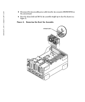
Removing the Back Fan Assembly release latch www.dell.com | support.dell.com 5 Disconnect the fan assembly power cable from the fan connector (REAR FANS) on the system board. 6 Press the release latch and lift the fan assembly straight up to clear the chassis (see Figure 2). Figure 2.
Removing the Back Fan Assembly release latch www.dell.com | support.dell.com 5 Disconnect the fan assembly power cable from the fan connector (REAR FANS) on the system board. 6 Press the release latch and lift the fan assembly straight up to clear the chassis (see Figure 2). Figure 2.
Removing the Back Fan Assembly
Page 3
...engaged (see Figure 2). 2 Connect the fan assembly power cable to either the entities claiming the marks and names or their products. Information in this text: Dell and the DELL logo are trademarks of Dell Computer Corporation is subject to the system. All rights ...thumbscrews securing the cooling shroud to change without the written permission of Dell Computer Corporation. Dell Computer Corporation disclaims any manner whatsoever without notice. © 2003 Dell Computer Corporation. www.dell.com | support.dell.com Replacing the Back Fan Assembly 1 Align the new fan assembly...
...engaged (see Figure 2). 2 Connect the fan assembly power cable to either the entities claiming the marks and names or their products. Information in this text: Dell and the DELL logo are trademarks of Dell Computer Corporation is subject to the system. All rights ...thumbscrews securing the cooling shroud to change without the written permission of Dell Computer Corporation. Dell Computer Corporation disclaims any manner whatsoever without notice. © 2003 Dell Computer Corporation. www.dell.com | support.dell.com Replacing the Back Fan Assembly 1 Align the new fan assembly...


