Service Manual
Page 32
... attached to the connector on the I/O panel and to the next section, "Observing the Boot Routine." 2-2 Dell PowerEdge 4100/180 and 4100/200 Systems Service Manual Inspect the keyboard to the appropriate procedure in Chapter 4, "Removing and Replacing Parts." For a serial mouse, the mouse interface cable must be attached to an appropriate connector on the...
... attached to the connector on the I/O panel and to the next section, "Observing the Boot Routine." 2-2 Dell PowerEdge 4100/180 and 4100/200 Systems Service Manual Inspect the keyboard to the appropriate procedure in Chapter 4, "Removing and Replacing Parts." For a serial mouse, the mouse interface cable must be attached to an appropriate connector on the...
Service Manual
Page 43
... chapter provides procedures for removing the components, assemblies, and subassemblies in the next section, "Precautionary Measures." Removing and Replacing Parts 4-1 Unless otherwise noted, each procedure assumes the following tools: • Small flat-blade screwdriver • Wide flat-blade screwdriver • Number 1 and number 2 Phillips-...chapter require the use of one or more of the following : • You have removed the computer covers. • You can replace or reinstall a part by performing the removal procedure in reverse order unless additional information is provided.
... chapter provides procedures for removing the components, assemblies, and subassemblies in the next section, "Precautionary Measures." Removing and Replacing Parts 4-1 Unless otherwise noted, each procedure assumes the following tools: • Small flat-blade screwdriver • Wide flat-blade screwdriver • Number 1 and number 2 Phillips-...chapter require the use of one or more of the following : • You have removed the computer covers. • You can replace or reinstall a part by performing the removal procedure in reverse order unless additional information is provided.
Service Manual
Page 44
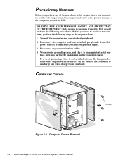
... personal safety and to prevent damage to the computer system from your body. Disconnect any static charge from ESD. face, such as a part of the back panel, on the computer, perform the following steps in this chapter, take a few moments to discharge any communications cables.... guard or some other unpainted metal surface on the back of the computer to read the following procedures. Computer Covers Removal 4-2 Dell PowerEdge 4100/180 and 4100/200 Systems Service Manual Before you perform any of the procedures in the sequence listed. 1. Computer Covers screw (6) Figure 4-1. ...
... personal safety and to prevent damage to the computer system from your body. Disconnect any static charge from ESD. face, such as a part of the back panel, on the computer, perform the following steps in this chapter, take a few moments to discharge any communications cables.... guard or some other unpainted metal surface on the back of the computer to read the following procedures. Computer Covers Removal 4-2 Dell PowerEdge 4100/180 and 4100/200 Systems Service Manual Before you perform any of the procedures in the sequence listed. 1. Computer Covers screw (6) Figure 4-1. ...
Service Manual
Page 45
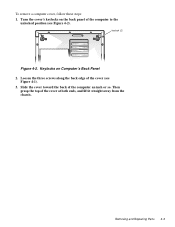
Loosen the three screws along the back edge of the computer an inch or so. Slide the cover toward the back of the cover (see Figure 4-2). Removing and Replacing Parts 4-3 Then grasp the top of the computer to the unlocked position (see Figure 4-1). 3. Turn the cover's keylocks on Computer's Back Panel 2. Keylocks on the back panel of the cover at both ends, and lift it straight away from the chassis. keylock (2) Figure 4-2. To remove a computer cover, follow these steps: 1.
Loosen the three screws along the back edge of the computer an inch or so. Slide the cover toward the back of the cover (see Figure 4-2). Removing and Replacing Parts 4-3 Then grasp the top of the computer to the unlocked position (see Figure 4-1). 3. Turn the cover's keylocks on Computer's Back Panel 2. Keylocks on the back panel of the cover at both ends, and lift it straight away from the chassis. keylock (2) Figure 4-2. To remove a computer cover, follow these steps: 1.
Service Manual
Page 47
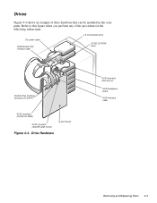
Drives Figure 4-4 shows an example of the procedures in the computer. Drive Hardware system board SCSI hard-disk drive bay (6) SCSI backplane board SCSI interface cable Removing and Replacing Parts 4-5 Refer to this figure when you perform any of drive hardware that can be installed in the following subsections. DC power cable diskette/tape drive interface cable 3.5-inch diskette drive SCSI2 CD-ROM drive diskette drive interface connector (FLOPPY) SCSI connector (SCSI2 CD-ROM) SCSI connector (BACKPLANE SCSI1) Figure 4-4.
Drives Figure 4-4 shows an example of the procedures in the computer. Drive Hardware system board SCSI hard-disk drive bay (6) SCSI backplane board SCSI interface cable Removing and Replacing Parts 4-5 Refer to this figure when you perform any of drive hardware that can be installed in the following subsections. DC power cable diskette/tape drive interface cable 3.5-inch diskette drive SCSI2 CD-ROM drive diskette drive interface connector (FLOPPY) SCSI connector (SCSI2 CD-ROM) SCSI connector (BACKPLANE SCSI1) Figure 4-4.
Service Manual
Page 49
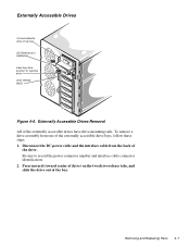
... drive position for optional drive drive-release tab(2) Figure 4-6. Be sure to record the power connector number and interface cable connector identification. 2. Removing and Replacing Parts 4-7 Externally Accessible Drives Removal All of the drive. Disconnect the DC power cable and the interface cable from one of the bay. To remove a drive...
... drive position for optional drive drive-release tab(2) Figure 4-6. Be sure to record the power connector number and interface cable connector identification. 2. Removing and Replacing Parts 4-7 Externally Accessible Drives Removal All of the drive. Disconnect the DC power cable and the interface cable from one of the bay. To remove a drive...
Service Manual
Page 51
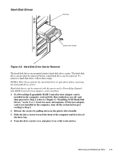
...Step 2 (refer to Chapter 6, "Installing SCSI Hard-Disk Drives," in the computer, wait until it on a flat work surface. Removing and Replacing Parts 4-9 If this host adapter card is installed in the User's Guide for the hard-disk drive to Step 2. 2. Hard-Disk Drives drive bay ... removed with the power on the plastic drive handle. 3. Release the carrier by pulling down before proceeding to spin down on if a PowerEdge Expandable RAID Controller host adapter card is free of the computer until the three indicators are mounted inside a hard-disk drive carrier. Slide ...
...Step 2 (refer to Chapter 6, "Installing SCSI Hard-Disk Drives," in the computer, wait until it on a flat work surface. Removing and Replacing Parts 4-9 If this host adapter card is installed in the User's Guide for the hard-disk drive to Step 2. 2. Hard-Disk Drives drive bay ... removed with the power on the plastic drive handle. 3. Release the carrier by pulling down before proceeding to spin down on if a PowerEdge Expandable RAID Controller host adapter card is free of the computer until the three indicators are mounted inside a hard-disk drive carrier. Slide ...

Service Manual
Page 53
... Backplane Board hard-disk drive carrier thumb screw hook (10) SCSI backplane board Figure 4-10. Disconnect all cables from the SCSI back- Removing and Replacing Parts 4-11 Disconnect the hard-disk drive carrier connectors from the SCSI backplane board. 3. SCSI Backplane Board Removal To remove the SCSI backplane board, follow these...
... Backplane Board hard-disk drive carrier thumb screw hook (10) SCSI backplane board Figure 4-10. Disconnect all cables from the SCSI back- Removing and Replacing Parts 4-11 Disconnect the hard-disk drive carrier connectors from the SCSI backplane board. 3. SCSI Backplane Board Removal To remove the SCSI backplane board, follow these...

Service Manual
Page 55
Disconnect the power supplies from the power-supply paralleling board. 3. Unscrew the thumb screw. 4. Removing and Replacing Parts 4-13 Disconnect all cables from the power-supply paralleling board by sliding each power supply toward the back of getting shocked. 1. Power-Supply Paralleling Board ...
Disconnect the power supplies from the power-supply paralleling board. 3. Unscrew the thumb screw. 4. Removing and Replacing Parts 4-13 Disconnect all cables from the power-supply paralleling board by sliding each power supply toward the back of getting shocked. 1. Power-Supply Paralleling Board ...
Service Manual
Page 57
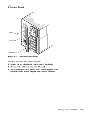
Control Panel Removal To remove the control panel, follow these steps: 1. Disengage the panel from the four hooks holding the control panel to the computer chassis, and lift the panel away from connector BP_to_CP. 3. Removing and Replacing Parts 4-15 Remove the screw holding the panel to the chassis. 2. Disconnect the cable from the computer. Control Panel screw control panel connector BP_to_CP Figure 4-14.
Control Panel Removal To remove the control panel, follow these steps: 1. Disengage the panel from the four hooks holding the control panel to the computer chassis, and lift the panel away from connector BP_to_CP. 3. Removing and Replacing Parts 4-15 Remove the screw holding the panel to the chassis. 2. Disconnect the cable from the computer. Control Panel screw control panel connector BP_to_CP Figure 4-14.
Service Manual
Page 59
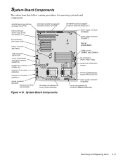
... connectors (FAN1, FAN2, FAN3) speed and configuration jumpers primary microprocessor socket (PROCESSOR1) power supply connector (POWER3) server-management bus connector (SMB BACKPLANE) Removing and Replacing Parts 4-17 System Board Components The subsections that follow contain procedures for removing system board components. diskette/tape drive interface connector (FLOPPY) EISA connectors (EISA1 [top...
... connectors (FAN1, FAN2, FAN3) speed and configuration jumpers primary microprocessor socket (PROCESSOR1) power supply connector (POWER3) server-management bus connector (SMB BACKPLANE) Removing and Replacing Parts 4-17 System Board Components The subsections that follow contain procedures for removing system board components. diskette/tape drive interface connector (FLOPPY) EISA connectors (EISA1 [top...
Service Manual
Page 61
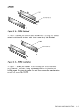
DIMM securing clip (2) 2. 1. Orient the DIMM to the socket, and press the DIMM straight down into the socket slot until they snap open. Removing and Replacing Parts 4-19 Figure 4-18. Then lift the DIMM away from its socket. Figure 4-19. DIMM Installation To replace a DIMM, push outward on the DIMM socket's securing clips until the DIMM is released from the socket. DIMMs DIMM securing clip (2) 2. 1. DIMM Removal To remove a DIMM, push outward on the securing clips at each end of the socket until the securing clips snap into place around both ends of the DIMM.
DIMM securing clip (2) 2. 1. Orient the DIMM to the socket, and press the DIMM straight down into the socket slot until they snap open. Removing and Replacing Parts 4-19 Figure 4-18. Then lift the DIMM away from its socket. Figure 4-19. DIMM Installation To replace a DIMM, push outward on the DIMM socket's securing clips until the DIMM is released from the socket. DIMMs DIMM securing clip (2) 2. 1. DIMM Removal To remove a DIMM, push outward on the securing clips at each end of the socket until the securing clips snap into place around both ends of the DIMM.

Service Manual
Page 62
... during system operations. Be sure the chip has had sufficient time to release the clip (see Figure 4-21). 4-20 Dell PowerEdge 4100/180 and 4100/200 Systems Service Manual Press down on the folded part of socket front tab Figure 4-20. Microprocessor and Heat Sink clip heat sink microprocessor socket thermal pad (bonded to heat...
... during system operations. Be sure the chip has had sufficient time to release the clip (see Figure 4-21). 4-20 Dell PowerEdge 4100/180 and 4100/200 Systems Service Manual Press down on the folded part of socket front tab Figure 4-20. Microprocessor and Heat Sink clip heat sink microprocessor socket thermal pad (bonded to heat...
Service Manual
Page 63
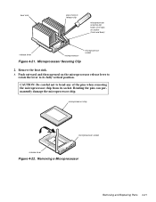
... lever Figure 4-22. Push outward and then upward on socket (front and back) release lever microprocessor microprocessor socket Figure 4-21. Removing a Microprocessor Removing and Replacing Parts 4-21 CAUTION: Be careful not to its socket. Bending the pins can permanently damage the microprocessor chip. heat sink press here to release clip microprocessor...
... lever Figure 4-22. Push outward and then upward on socket (front and back) release lever microprocessor microprocessor socket Figure 4-21. Removing a Microprocessor Removing and Replacing Parts 4-21 CAUTION: Be careful not to its socket. Bending the pins can permanently damage the microprocessor chip. heat sink press here to release clip microprocessor...
Service Manual
Page 65
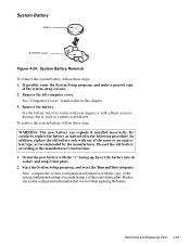
... recommended by the manufacturer. Be careful to the manufacturer's instructions. 1. Start the System Setup program, and reset the Time and Date categories. Removing and Replacing Parts 4-23 If possible, enter the System Setup program, and make a printed copy of the removal procedure. Remove the battery. In addition, replace the old battery...
... recommended by the manufacturer. Be careful to the manufacturer's instructions. 1. Start the System Setup program, and reset the Time and Date categories. Removing and Replacing Parts 4-23 If possible, enter the System Setup program, and make a printed copy of the removal procedure. Remove the battery. In addition, replace the old battery...


