Service Manual
Page 3
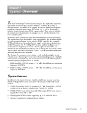
... have one or two Pentium Pro microprocessors. The Pentium Pro microprocessor contains a built-in a traditional personal computer, Dell PowerEdge 4100 systems include the following new and/or advanced features: • 256 KB (PowerEdge 4100/180 systems) or 512 KB (PowerEdge 4100/200 systems) of cache memory internal to the Pentium Pro module • 64 MB of 72-bit...
... have one or two Pentium Pro microprocessors. The Pentium Pro microprocessor contains a built-in a traditional personal computer, Dell PowerEdge 4100 systems include the following new and/or advanced features: • 256 KB (PowerEdge 4100/180 systems) or 512 KB (PowerEdge 4100/200 systems) of cache memory internal to the Pentium Pro module • 64 MB of 72-bit...

Service Manual
Page 4
...; Integrated ultra-wide and ultra-narrow SCSI controllers • Integrated server management circuitry that monitors critical system volt- For information about installing the PowerEdge 4100 systems in a rack, see "Technical Specifications" found later in this chapter. (For more information about the Quick Test option in the CD...; CD-ROM drive standard in this chapter. ages and temperatures, as well as the operation of system features, see the "Dell PowerEdge 4100 and 6100 Systems Rack Kit Installation Guide" (P/N 40722). 1-2 Dell PowerEdge 4100/180 and 4100/200 Systems Service Manual
...; Integrated ultra-wide and ultra-narrow SCSI controllers • Integrated server management circuitry that monitors critical system volt- For information about installing the PowerEdge 4100 systems in a rack, see "Technical Specifications" found later in this chapter. (For more information about the Quick Test option in the CD...; CD-ROM drive standard in this chapter. ages and temperatures, as well as the operation of system features, see the "Dell PowerEdge 4100 and 6100 Systems Rack Kit Installation Guide" (P/N 40722). 1-2 Dell PowerEdge 4100/180 and 4100/200 Systems Service Manual

Service Manual
Page 6
... SCSI hard-disk drive activity indicator CAUTION: To avoid possible data or file structure corruptions, the frontpanel reset button should be rebooted by pressing . 1-4 Dell PowerEdge 4100/180 and 4100/200 Systems Service Manual If you are using the reset button to initiate a hardware reset, close any open application programs and files if possible. Before...
... SCSI hard-disk drive activity indicator CAUTION: To avoid possible data or file structure corruptions, the frontpanel reset button should be rebooted by pressing . 1-4 Dell PowerEdge 4100/180 and 4100/200 Systems Service Manual If you are using the reset button to initiate a hardware reset, close any open application programs and files if possible. Before...
Service Manual
Page 8
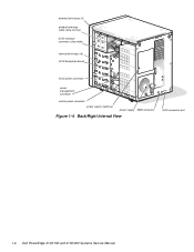
Back/Right Internal View SCSI connector port 1-6 Dell PowerEdge 4100/180 and 4100/200 Systems Service Manual external drive bays (4) diskette interface cable (ultra-narrow) SCSI interface connector (ultra-wide) internal drive bays (6) SCSI backplane board SCSI power connector server management connector control panel connector power supply (optional) power supply SMB connector Figure 1-4.
Back/Right Internal View SCSI connector port 1-6 Dell PowerEdge 4100/180 and 4100/200 Systems Service Manual external drive bays (4) diskette interface cable (ultra-narrow) SCSI interface connector (ultra-wide) internal drive bays (6) SCSI backplane board SCSI power connector server management connector control panel connector power supply (optional) power supply SMB connector Figure 1-4.
Service Manual
Page 10
... Plug and Play ISA expansion cards, and PCI expansion cards. Chapter 5, "Using the EISA Configuration Utility," in the Dell PowerEdge 4100/180 and 4100/200 Systems User's Guide describes the EISA Configuration Utility and provides instructions for information on removing and replacing DIMMs. Advanced ..., IRQ lines, and DMA channels to configure the system. System Memory The PowerEdge 4100 systems have been configured with the Intel LANDesk® Server Management suite. 1-8 Dell PowerEdge 4100/180 and 4100/200 Systems Service Manual The system board has eight 168-pin DIMM sockets. ...
... Plug and Play ISA expansion cards, and PCI expansion cards. Chapter 5, "Using the EISA Configuration Utility," in the Dell PowerEdge 4100/180 and 4100/200 Systems User's Guide describes the EISA Configuration Utility and provides instructions for information on removing and replacing DIMMs. Advanced ..., IRQ lines, and DMA channels to configure the system. System Memory The PowerEdge 4100 systems have been configured with the Intel LANDesk® Server Management suite. 1-8 Dell PowerEdge 4100/180 and 4100/200 Systems Service Manual The system board has eight 168-pin DIMM sockets. ...
Service Manual
Page 11
...," in the other devices, their configuration requirements are installed essentially the same way as other two bays. In the standard Dell PowerEdge 4100 system configuration, the Ultra/Wide SCSI host adapter on the system board. SCSI Configuration Guidelines Although SCSI devices are different.... with 256 colors. SCSI Hard-Disk Drives Six internal hot-pluggable hard-disk drive bays are normally used in the Dell PowerEdge 4100/180 and 4100/200 Systems Installation and Troubleshooting Guide. NOTES: The externally accessible drive bays at the front of the computer are located...
...," in the other devices, their configuration requirements are installed essentially the same way as other two bays. In the standard Dell PowerEdge 4100 system configuration, the Ultra/Wide SCSI host adapter on the system board. SCSI Configuration Guidelines Although SCSI devices are different.... with 256 colors. SCSI Hard-Disk Drives Six internal hot-pluggable hard-disk drive bays are normally used in the Dell PowerEdge 4100/180 and 4100/200 Systems Installation and Troubleshooting Guide. NOTES: The externally accessible drive bays at the front of the computer are located...
Service Manual
Page 12
... to the Ultra/Wide SCSI host adapter need no termination. - Devices attached to the cable should have a unique SCSI ID number from Dell, the default SCSI ID numbers are assigned as follows: • The computer's built-in Ultra/Narrow SCSI host adapter is configured through ...host adapter or to the end connector on the SCSI cable, and leave the terminator enabled on disabling the device's terminator. 1-10 Dell PowerEdge 4100/180 and 4100/200 Systems Service Manual Therefore, regardless of the SCSI cable connects to the computer's built-in order by the SCSI backplane. Disable ...
... to the Ultra/Wide SCSI host adapter need no termination. - Devices attached to the cable should have a unique SCSI ID number from Dell, the default SCSI ID numbers are assigned as follows: • The computer's built-in Ultra/Narrow SCSI host adapter is configured through ...host adapter or to the end connector on the SCSI cable, and leave the terminator enabled on disabling the device's terminator. 1-10 Dell PowerEdge 4100/180 and 4100/200 Systems Service Manual Therefore, regardless of the SCSI cable connects to the computer's built-in order by the SCSI backplane. Disable ...
Service Manual
Page 14
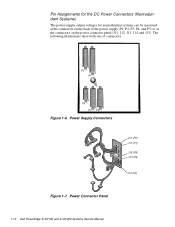
The following illustrations show both sets of the power supply (P1, P2, P3, P4, and P5) or at the connectors on the back of connectors. Power Connector Panel 1-12 Dell PowerEdge 4100/180 and 4100/200 Systems Service Manual Power Supply Connectors J12 (P2) J11 (P1) J15 (P5) J14 (P4) J13 (P3) Figure 1-7. Pin Assignments for the DC Power Connectors (Nonredundant Systems) The power-supply output voltages for nonredundant systems can be measured at the connectors on the power connector panel (J11, J12, J13, J14, and J15). P2 P1 P5 P4 P3 Figure 1-6.
The following illustrations show both sets of the power supply (P1, P2, P3, P4, and P5) or at the connectors on the back of connectors. Power Connector Panel 1-12 Dell PowerEdge 4100/180 and 4100/200 Systems Service Manual Power Supply Connectors J12 (P2) J11 (P1) J15 (P5) J14 (P4) J13 (P3) Figure 1-7. Pin Assignments for the DC Power Connectors (Nonredundant Systems) The power-supply output voltages for nonredundant systems can be measured at the connectors on the power connector panel (J11, J12, J13, J14, and J15). P2 P1 P5 P4 P3 Figure 1-6.
Service Manual
Page 16
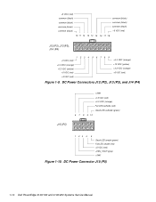
... (orange) +12 VDC (yellow) +5 VDC (red) +5 VDC (red) +3.3 VDC (orange) +12 VDC (yellow) +3.3 VDC (orange) +5 VDC (red) Figure 1-9. DC Power Connector J15 (P5) 1-14 Dell PowerEdge 4100/180 and 4100/200 Systems Service Manual DC Power Connectors J12 (P2), J13 (P3), and J14 (P4) J15 (P5) +SW1 +12 VDC (red) +3.3 VDC (orange) Fail LED cathode...
... (orange) +12 VDC (yellow) +5 VDC (red) +5 VDC (red) +3.3 VDC (orange) +12 VDC (yellow) +3.3 VDC (orange) +5 VDC (red) Figure 1-9. DC Power Connector J15 (P5) 1-14 Dell PowerEdge 4100/180 and 4100/200 Systems Service Manual DC Power Connectors J12 (P2), J13 (P3), and J14 (P4) J15 (P5) +SW1 +12 VDC (red) +3.3 VDC (orange) Fail LED cathode...
Service Manual
Page 18
Power-Supply Paralleling Board Connectors 1-16 Dell PowerEdge 4100/180 and 4100/200 Systems Service Manual Pin Assignments for the DC Power Connectors (Redundant Systems) The power-supply output voltages for redundant systems can be measured at the connectors on the power-supply paralleling board (PWR1, PWR2, PWR3, PWRSCSI, and PWRFD) or at the connectors on the end of the wire bundles extending from these connectors (PWR1, PWR2, PWR3, DDBP, and FD1-FD4). PWR1 PWRFD (FD1-FD4) PWR2 diagnostics port PWR3 PWRSCSI (DDBP) Figure 1-12.
Power-Supply Paralleling Board Connectors 1-16 Dell PowerEdge 4100/180 and 4100/200 Systems Service Manual Pin Assignments for the DC Power Connectors (Redundant Systems) The power-supply output voltages for redundant systems can be measured at the connectors on the power-supply paralleling board (PWR1, PWR2, PWR3, PWRSCSI, and PWRFD) or at the connectors on the end of the wire bundles extending from these connectors (PWR1, PWR2, PWR3, DDBP, and FD1-FD4). PWR1 PWRFD (FD1-FD4) PWR2 diagnostics port PWR3 PWRSCSI (DDBP) Figure 1-12.
Service Manual
Page 20
... 8 are connected to FD3 and FD4. +5 VDC (red) common (black) common (black) +12 VDC (yellow) Figure 1-16. DC Power Connector PWRFD (FD1-FD4) 1-18 Dell PowerEdge 4100/180 and 4100/200 Systems Service Manual common (black) common (black) common (black) common (black) common (black) common (black) common (black) 8 9 10 11 12 13 14 PWRSCSI (DDBP...
... 8 are connected to FD3 and FD4. +5 VDC (red) common (black) common (black) +12 VDC (yellow) Figure 1-16. DC Power Connector PWRFD (FD1-FD4) 1-18 Dell PowerEdge 4100/180 and 4100/200 Systems Service Manual common (black) common (black) common (black) common (black) common (black) common (black) common (black) 8 9 10 11 12 13 14 PWRSCSI (DDBP...
Service Manual
Page 22
System Board Components 1-20 Dell PowerEdge 4100/180 and 4100/200 Systems Service Manual diskette/tape drive interface Ultra/Narrow SCSI host adapter connector (FLOPPY) connector (SCSI2 CD-ROM) Ultra/Wide SCSI host adapter connector (...
System Board Components 1-20 Dell PowerEdge 4100/180 and 4100/200 Systems Service Manual diskette/tape drive interface Ultra/Narrow SCSI host adapter connector (FLOPPY) connector (SCSI2 CD-ROM) Ultra/Wide SCSI host adapter connector (...

Service Manual
Page 24
...EISA EISA Configuration Utility Not installed (utility settings are retained at system boot) VGA Integrated video controller Installed (controller is 180 MHz Interrupt Assignments Table 1-3. do not change ) 200MHZ Microprocessor speed Installed only if the microprocessor's internal speed is 200 MHz... /O controller to indicate that device connected to indicate that diskette drive requires service IRQ7 Generated by expansion card 1-22 Dell PowerEdge 4100/180 and 4100/200 Systems Service Manual IRQ4 for COM1 or COM3) IRQ5 Available for use by expansion card unless this IRQ line is...
...EISA EISA Configuration Utility Not installed (utility settings are retained at system boot) VGA Integrated video controller Installed (controller is 180 MHz Interrupt Assignments Table 1-3. do not change ) 200MHZ Microprocessor speed Installed only if the microprocessor's internal speed is 200 MHz... /O controller to indicate that device connected to indicate that diskette drive requires service IRQ7 Generated by expansion card 1-22 Dell PowerEdge 4100/180 and 4100/200 Systems Service Manual IRQ4 for COM1 or COM3) IRQ5 Available for use by expansion card unless this IRQ line is...
Service Manual
Page 26
...-card connector data width (maximum 32 bits PCI expansion-card connector size 120 pins PCI expansion-card connector data width (maximum 32 bits 1-24 Dell PowerEdge 4100/180 and 4100/200 Systems Service Manual Technical Specifications Table 1-5. Technical Specifications Microprocessor Microprocessor type single or dual Intel Pentium Pro microprocessors Microprocessor speed 200 MHz internal (66...
...-card connector data width (maximum 32 bits PCI expansion-card connector size 120 pins PCI expansion-card connector data width (maximum 32 bits 1-24 Dell PowerEdge 4100/180 and 4100/200 Systems Service Manual Technical Specifications Table 1-5. Technical Specifications Microprocessor Microprocessor type single or dual Intel Pentium Pro microprocessors Microprocessor speed 200 MHz internal (66...
Service Manual
Page 28
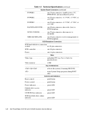
one 16-pin connector (server management) to CD-ROM SMB BACKPLANE. . . . . Technical Specifications (continued) System Board Connectors (continued) POWER1 one 18-pin connector: standby power, I2 C, PWRGOOD, and miscellaneous power POWER2 one 20-pin connector: +3.3 VDC, +5 VDC, or +12 VDC POWER3 one 14-pin connectors Video Video type embedded PCI (see User's Guide for specifications) Video memory 1 MB Key Combinations one 68-pin connector, ultra-wide (fast), to SCSI backplane SCSI2 CD-ROM one 50-pin connector, ultra-narrow, to SCSI backplane SCSI Backplane Connectors SCSI hard-...
one 16-pin connector (server management) to CD-ROM SMB BACKPLANE. . . . . Technical Specifications (continued) System Board Connectors (continued) POWER1 one 18-pin connector: standby power, I2 C, PWRGOOD, and miscellaneous power POWER2 one 20-pin connector: +3.3 VDC, +5 VDC, or +12 VDC POWER3 one 14-pin connectors Video Video type embedded PCI (see User's Guide for specifications) Video memory 1 MB Key Combinations one 68-pin connector, ultra-wide (fast), to SCSI backplane SCSI2 CD-ROM one 50-pin connector, ultra-narrow, to SCSI backplane SCSI Backplane Connectors SCSI hard-...
Service Manual
Page 30
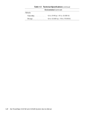
Technical Specifications (continued) Environmental (continued) Altitude: Operating 16 to 3048 m (-50 to 10,000 ft) Storage 16 to 10,600 m (-50 to 35,000 ft) z 1-28 Dell PowerEdge 4100/180 and 4100/200 Systems Service Manual Table 1-5.
Technical Specifications (continued) Environmental (continued) Altitude: Operating 16 to 3048 m (-50 to 10,000 ft) Storage 16 to 10,600 m (-50 to 35,000 ft) z 1-28 Dell PowerEdge 4100/180 and 4100/200 Systems Service Manual Table 1-5.
Service Manual
Page 32
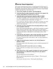
... port connectors, and its captive screws must be necessary to ensure that secure these steps: 1. Proceed to the next section, "Observing the Boot Routine." 2-2 Dell PowerEdge 4100/180 and 4100/200 Systems Service Manual Verify that any obvious damage or improper settings. Verify that the keyboard and mouse interface cables are properly connected. For proper...
... port connectors, and its captive screws must be necessary to ensure that secure these steps: 1. Proceed to the next section, "Observing the Boot Routine." 2-2 Dell PowerEdge 4100/180 and 4100/200 Systems Service Manual Verify that any obvious damage or improper settings. Verify that the keyboard and mouse interface cables are properly connected. For proper...
Service Manual
Page 34
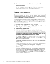
... a DIMM, remove it . Yes. No. Remove the left computer cover. 3. Then reinstall the cardmounting bracket's retaining screw. 2-4 Dell PowerEdge 4100/180 and 4100/200 Systems Service Manual Does the menu appear? Proceed to locate components in Chapter 4. Grasp the card by its top corners, and carefully... driver to cool before you perform the visual inspection, refer to "System Features" in Chapter 4. Observe the monitor screen for the Dell Server Assistant Menu. Reinsert the card in this section, ensure that the chips are fully seated in until fully seated. A simple ...
... a DIMM, remove it . Yes. No. Remove the left computer cover. 3. Then reinstall the cardmounting bracket's retaining screw. 2-4 Dell PowerEdge 4100/180 and 4100/200 Systems Service Manual Does the menu appear? Proceed to locate components in Chapter 4. Grasp the card by its top corners, and carefully... driver to cool before you perform the visual inspection, refer to "System Features" in Chapter 4. Observe the monitor screen for the Dell Server Assistant Menu. Reinsert the card in this section, ensure that the chips are fully seated in until fully seated. A simple ...
Service Manual
Page 36
...Menu appears, allowing you to choose the following options or exit to the proper troubleshooting steps for determining the source of the problem, call Dell for a thorough check of the problem or leads to MS-DOS: • Run All Tests - Runs all test groups to quickly ... of the system • Run Quick Tests - For instructions, see Chapter 11, "Getting Help," in main memory, and the Dell Server Assistant loads, select the Run System Utilities icon. If no errors are found in the Installation and Troubleshooting Guide. 2-6 Dell PowerEdge 4100/180 and 4100/200 Systems Service Manual
...Menu appears, allowing you to choose the following options or exit to the proper troubleshooting steps for determining the source of the problem, call Dell for a thorough check of the problem or leads to MS-DOS: • Run All Tests - Runs all test groups to quickly ... of the system • Run Quick Tests - For instructions, see Chapter 11, "Getting Help," in main memory, and the Dell Server Assistant loads, select the Run System Utilities icon. If no errors are found in the Installation and Troubleshooting Guide. 2-6 Dell PowerEdge 4100/180 and 4100/200 Systems Service Manual
Service Manual
Page 38
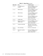
... needs to be rebooted. Beep Code 1-3-3-1 1-3-4-1 1-3-4-3 1-4-1-1 1-4-2-1 1-4-3-1 2-2-3-1 3-2-2-1 4-2-4-4 4-2-4-3 Table 3-1. Reseat DIMMs or replace system board. Reseat DIMMs or replace system board. Reseat DIMMs or replace system board. 3-2 Dell PowerEdge 4100/180 and 4100/200 Systems Service Manual
... needs to be rebooted. Beep Code 1-3-3-1 1-3-4-1 1-3-4-3 1-4-1-1 1-4-2-1 1-4-3-1 2-2-3-1 3-2-2-1 4-2-4-4 4-2-4-3 Table 3-1. Reseat DIMMs or replace system board. Reseat DIMMs or replace system board. Reseat DIMMs or replace system board. 3-2 Dell PowerEdge 4100/180 and 4100/200 Systems Service Manual
