
Service Manual
Page 3
Contents Chapter 1 System Overview 1-1 System Features 1-1 System Memory 1-5 Advanced Expansion Subsystem 1-6 Integrated Server Management 1-6 Video Controller 1-6 Integrated SCSI Controller 1-6 SCSI Hard-Disk Drives 1-7 SCSI Configuration Guidelines 1-7 SCSI ID Numbers 1-7 Device Termination 1-8 System Unit 1-10 System Power Supply 1-10 Pin Assignments for the DC Power Connectors 1-10 DC Power Distribution 1-12 System Board Layout 1-14 System Board Jumpers 1-15 Interrupt Assignments 1-17 DMA Channel Assignments 1-18 Technical Specifications 1-19 v
Contents Chapter 1 System Overview 1-1 System Features 1-1 System Memory 1-5 Advanced Expansion Subsystem 1-6 Integrated Server Management 1-6 Video Controller 1-6 Integrated SCSI Controller 1-6 SCSI Hard-Disk Drives 1-7 SCSI Configuration Guidelines 1-7 SCSI ID Numbers 1-7 Device Termination 1-8 System Unit 1-10 System Power Supply 1-10 Pin Assignments for the DC Power Connectors 1-10 DC Power Distribution 1-12 System Board Layout 1-14 System Board Jumpers 1-15 Interrupt Assignments 1-17 DMA Channel Assignments 1-18 Technical Specifications 1-19 v
Service Manual
Page 9
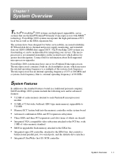
... 1-1 System Features In addition to the standard features found in a traditional personal computer, Dell PowerEdge 2200 systems include the following new and/or advanced features: • 512 KB of cache memory internal to each Pentium II microprocessor module • 32 MB of 72-bit-wide, ... of which increases the internal operating frequency to a multiple of video memory standard • BIOS in clock multiplier circuit, which are freestanding or can be rackmounted for greater heat dissipation. PowerEdge 2200 systems incorporate the high-performance PCI local bus as well as the ...
... 1-1 System Features In addition to the standard features found in a traditional personal computer, Dell PowerEdge 2200 systems include the following new and/or advanced features: • 512 KB of cache memory internal to each Pentium II microprocessor module • 32 MB of 72-bit-wide, ... of which increases the internal operating frequency to a multiple of video memory standard • BIOS in clock multiplier circuit, which are freestanding or can be rackmounted for greater heat dissipation. PowerEdge 2200 systems incorporate the high-performance PCI local bus as well as the ...

Service Manual
Page 13
... be in pairs. The 72-bit-wide, buffered, EDO DIMMs support the ECC feature, which detects memory errors and corrects single-bit memory errors. The ECC feature is built into the memory controller on the system board. System Overview 1-5 power-supply selector switch AC power input connector I/O panel... and 128-MB buffered, EDO-type DIMMs. The system board has four 168-pin DIMM sockets. The ECC feature provides more reliable memory and less downtime. tem memory operates at 60 nanoseconds (ns) or faster. The DIMMs do not have to be expanded up to DIMM_D (lower). • ...
... be in pairs. The 72-bit-wide, buffered, EDO DIMMs support the ECC feature, which detects memory errors and corrects single-bit memory errors. The ECC feature is built into the memory controller on the system board. System Overview 1-5 power-supply selector switch AC power input connector I/O panel... and 128-MB buffered, EDO-type DIMMs. The system board has four 168-pin DIMM sockets. The ECC feature provides more reliable memory and less downtime. tem memory operates at 60 nanoseconds (ns) or faster. The DIMMs do not have to be expanded up to DIMM_D (lower). • ...

Service Manual
Page 14
... The video controller is not upgradable. Maximum noninterlaced resolutions are located on the system board (see "Adding Memory" in Chapter 7 of the Dell PowerEdge 2200 Systems User's Guide. The integrated SCSI controller provides control for the three SCSI hard-disk drives in the...for information on the system board. Chapter 5, "Using the EISA Configuration Utility," in the lower externally accessible drive bay. 1-6 Dell PowerEdge 2200 Systems Service Manual Integrated SCSI Controller A single integrated SCSI controller provides an Ultra/Wide (fast-20) SCSI interface through a ...
... The video controller is not upgradable. Maximum noninterlaced resolutions are located on the system board (see "Adding Memory" in Chapter 7 of the Dell PowerEdge 2200 Systems User's Guide. The integrated SCSI controller provides control for the three SCSI hard-disk drives in the...for information on the system board. Chapter 5, "Using the EISA Configuration Utility," in the lower externally accessible drive bay. 1-6 Dell PowerEdge 2200 Systems Service Manual Integrated SCSI Controller A single integrated SCSI controller provides an Ultra/Wide (fast-20) SCSI interface through a ...

Service Manual
Page 21
... drive CD-ROM P3 drive P4 3.5-inch diskette drive P5 internal hard-disk drive P6 internal hard-disk drive internal hard-disk drive Y-cable main memory sockets DIMM_D DIMM_C DIMM_B DIMM_A PROC_1 +12 VDC +5 VFP +5 VDC fuse +5 VDC +5 VDC processor core regulator FAN PANEL KYBD MOUSE +3.3 VDC core VCC (+1.8 to +3.5 VDC...
... drive CD-ROM P3 drive P4 3.5-inch diskette drive P5 internal hard-disk drive P6 internal hard-disk drive internal hard-disk drive Y-cable main memory sockets DIMM_D DIMM_C DIMM_B DIMM_A PROC_1 +12 VDC +5 VFP +5 VDC fuse +5 VDC +5 VDC processor core regulator FAN PANEL KYBD MOUSE +3.3 VDC core VCC (+1.8 to +3.5 VDC...

Service Manual
Page 27
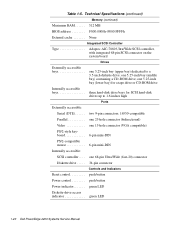
... 66 MHz (matches external processor speed) Diskette/communications ports 24 MHz from the system clock SCSI channel 40 MHz Memory Architecture 72-bit (64 data bits plus 8 ECC bits), noninterleaved, buffered, EDO-type memory DIMM sockets four 168-pin sockets DIMM capacities . . . . . 32 and 128 MB (DIMMs are 60 ns or faster...
... 66 MHz (matches external processor speed) Diskette/communications ports 24 MHz from the system clock SCSI channel 40 MHz Memory Architecture 72-bit (64 data bits plus 8 ECC bits), noninterleaved, buffered, EDO-type memory DIMM sockets four 168-pin sockets DIMM capacities . . . . . 32 and 128 MB (DIMMs are 60 ns or faster...
Service Manual
Page 28
... connector Controls and Indicators Reset control push button Power control push button Power indicator green LED Diskette-drive access indicator green LED 1-20 Dell PowerEdge 2200 Systems Service Manual one 5.25-inch bay (middle bay) containing a CD-ROM drive; one 5.25-inch bay (lower bay) ...connector (bidirectional) Video one 5.25-inch bay (upper bay) dedicated to a 3.5-inch diskette drive; Technical Specifications (continued) Memory (continued) Maximum RAM 512 MB BIOS address F000:0000h-F000:FFFFh External cache None Integrated SCSI Controller Type Adaptec AIC-7880...
... connector Controls and Indicators Reset control push button Power control push button Power indicator green LED Diskette-drive access indicator green LED 1-20 Dell PowerEdge 2200 Systems Service Manual one 5.25-inch bay (middle bay) containing a CD-ROM drive; one 5.25-inch bay (lower bay) ...connector (bidirectional) Video one 5.25-inch bay (upper bay) dedicated to a 3.5-inch diskette drive; Technical Specifications (continued) Memory (continued) Maximum RAM 512 MB BIOS address F000:0000h-F000:FFFFh External cache None Integrated SCSI Controller Type Adaptec AIC-7880...
Service Manual
Page 29
... access indicator green LED CD-ROM drive access indicator green LED Video Video type ATI mach64 (264VT) PCI video controller with integrated VGA connector Video memory (standard 1 MB (not upgradable) Power DC power supply: Wattage 230 W Voltage 115 V at 60 Hz; 230 V at 50 Hz Backup battery 3.0-V CR2032 lithium coin cell...
... access indicator green LED CD-ROM drive access indicator green LED Video Video type ATI mach64 (264VT) PCI video controller with integrated VGA connector Video memory (standard 1 MB (not upgradable) Power DC power supply: Wattage 230 W Voltage 115 V at 60 Hz; 230 V at 50 Hz Backup battery 3.0-V CR2032 lithium coin cell...
Service Manual
Page 33
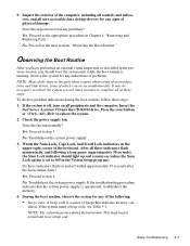
... Troubleshoot the system power supply. If the system emits a beep code, see Table 3-1. This single beep is normal and is operational, troubleshoot the memory. 4. Check the power supply fan. No. If the troubleshooting procedure indicates that indicates an error con- During the boot routine, observe the system ...in the previous section, you should light up and remain on (unless the Num Lock option is a series of the keyboard. Insert the Dell Server Assistant CD into the CD-ROM drive. Do these steps: 1. NOTE: The system beeps once during the boot routine, follow these ...
... Troubleshoot the system power supply. If the system emits a beep code, see Table 3-1. This single beep is normal and is operational, troubleshoot the memory. 4. Check the power supply fan. No. If the troubleshooting procedure indicates that indicates an error con- During the boot routine, observe the system ...in the previous section, you should light up and remain on (unless the Num Lock option is a series of the keyboard. Insert the Dell Server Assistant CD into the CD-ROM drive. Do these steps: 1. NOTE: The system beeps once during the boot routine, follow these ...
Service Manual
Page 35
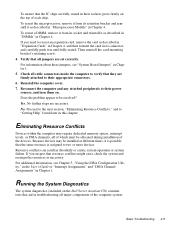
...or system failure. Proceed to the next section, "Eliminating Resource Conflicts," and to their appropriate connectors. 6. Because devices may require dedicated memory spaces, interrupt levels, or DMA channels, all of which must be installed at different times, it is possible that the same resource is...Yes. Verify that all jumpers are necessary. To ensure that the IC chips are fully seated in their sockets, press firmly on the Dell Server Assistant CD) contains tests that aid in troubleshooting all major components of the computer system. For information about these jumpers, see ...
...or system failure. Proceed to the next section, "Eliminating Resource Conflicts," and to their appropriate connectors. 6. Because devices may require dedicated memory spaces, interrupt levels, or DMA channels, all of which must be installed at different times, it is possible that the same resource is...Yes. Verify that all jumpers are necessary. To ensure that the IC chips are fully seated in their sockets, press firmly on the Dell Server Assistant CD) contains tests that aid in troubleshooting all major components of the computer system. For information about these jumpers, see ...

Service Manual
Page 38
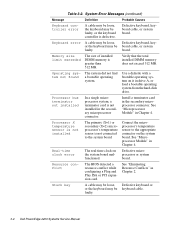
... system board. Memory controller or DIMM failure Defective DIMMs or system board. Reseat the DIMMs or replace the system board. Keyboard controller error Defective DIMMs or system board. Reseat the DIMMs or replace the system board. Gate A20 failure Defective system board. Gate A20 failure Defective system board. 3-2 Dell PowerEdge 2200 Systems Service Manual...
... system board. Memory controller or DIMM failure Defective DIMMs or system board. Reseat the DIMMs or replace the system board. Keyboard controller error Defective DIMMs or system board. Reseat the DIMMs or replace the system board. Gate A20 failure Defective system board. Gate A20 failure Defective system board. 3-2 Dell PowerEdge 2200 Systems Service Manual...
Service Manual
Page 40
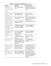
...a resource conflict while configuring a Plug and Play ISA or PCI expansion card. Verify that the total installed DIMM memory does not exceed 512 MB. Processor bus terminator not installed In a single microprocessor system, a terminator card is not... "Microprocessor Module" in Chapter 4. Table 3-2. Defective keyboard, keyboard cable, or system board. Memory size limit exceeded The size of installed DIMM memory is defective. faulty. 3-4 Dell PowerEdge 2200 Systems Service Manual System Error Messages (continued) Message Definition Probable Causes Keyboard controller error A cable...
...a resource conflict while configuring a Plug and Play ISA or PCI expansion card. Verify that the total installed DIMM memory does not exceed 512 MB. Processor bus terminator not installed In a single microprocessor system, a terminator card is not... "Microprocessor Module" in Chapter 4. Table 3-2. Defective keyboard, keyboard cable, or system board. Memory size limit exceeded The size of installed DIMM memory is defective. faulty. 3-4 Dell PowerEdge 2200 Systems Service Manual System Error Messages (continued) Message Definition Probable Causes Keyboard controller error A cable...
Service Manual
Page 41
... - If the problem persists, the fan must be malfunctioning. Run the System Setup program to restore your system configuration. Defective microprocessor or system board. System memory size has changed - Run Configuration Utility A DIMM was added or Reseat the DIMMs or removed. The DIMMs replace the DIMMs. are improperly seated. Defective microprocessor...
... - If the problem persists, the fan must be malfunctioning. Run the System Setup program to restore your system configuration. Defective microprocessor or system board. System memory size has changed - Run Configuration Utility A DIMM was added or Reseat the DIMMs or removed. The DIMMs replace the DIMMs. are improperly seated. Defective microprocessor...
Service Manual
Page 67
... by a right arrow to the initial menu bar selections, some system features • Security menu - Contains configuration selec- Shows which is used to load into memory and you wait too long, the operating system begins to change the system configuration information stored in areas where information is presented (see Figure A-1): •...
... by a right arrow to the initial menu bar selections, some system features • Security menu - Contains configuration selec- Shows which is used to load into memory and you wait too long, the operating system begins to change the system configuration information stored in areas where information is presented (see Figure A-1): •...

Service Manual
Page 69
...Black on black - Also used for help box title box Dell System PowerEdge 2200 Setup Main Advanced Security Exit Time: [5:01:96] Date: [June 04, 1997] Diskette Drive A: [1.44 MB, 3.5 inch] Diskette Drive B: [Not Installed] Fast Video BIOS: [On and Cached] Memory Cache: [Enable] Boot Sequence: [A: then C:] Numlock: ...the field. Time kept in a 24-hour format. Press , , or selects fields Processor 1: Processor 2: Level 2 Cache: Base Memory: Extended Memory: Video Memory: Service Tag: Asset Tag: Pentium II 266 Pentium II 266 512 KB 640 KB 31 MB 1 MB AB12Z 123456789A F1 Help ...
...Black on black - Also used for help box title box Dell System PowerEdge 2200 Setup Main Advanced Security Exit Time: [5:01:96] Date: [June 04, 1997] Diskette Drive A: [1.44 MB, 3.5 inch] Diskette Drive B: [Not Installed] Fast Video BIOS: [On and Cached] Memory Cache: [Enable] Boot Sequence: [A: then C:] Numlock: ...the field. Time kept in a 24-hour format. Press , , or selects fields Processor 1: Processor 2: Level 2 Cache: Base Memory: Extended Memory: Video Memory: Service Tag: Asset Tag: Pentium II 266 Pentium II 266 512 KB 640 KB 31 MB 1 MB AB12Z 123456789A F1 Help ...

Service Manual
Page 70
.... Processor 1 and Processor 2 Displays type of memory available as extended memory. Extended Memory Displays amount of microprocessor(s) installed. Diskette Drive A Diskette Drive B Identifies type of memory available to ten characters) if one is activated at boot. See Figure A-2. Date Resets date on -board speaker. A-4 Dell PowerEdge 2200 Systems Service Manual Base Memory Displays amount of diskette drives installed...
.... Processor 1 and Processor 2 Displays type of memory available as extended memory. Extended Memory Displays amount of microprocessor(s) installed. Diskette Drive A Diskette Drive B Identifies type of memory available to ten characters) if one is activated at boot. See Figure A-2. Date Resets date on -board speaker. A-4 Dell PowerEdge 2200 Systems Service Manual Base Memory Displays amount of diskette drives installed...
Service Manual
Page 81
..., 1-15 removal, 4-24 system cooling fan removal, 4-14 system diagnostics, running, 2-5 system error messages list of, 3-3 system features, 1-1 system memory, 1-5 system power supply, 1-10 System Setup program Advanced menu, A-6 Boot Options submenu, A-5 Index 3 M memory, system, 1-5 messages, error, 3-3 microprocessor about, 1-1, 1-19 connectors, 4-15 module removal, 4-18 retention bracket, 4-22 terminator card, 4-21 MOUSE...
..., 1-15 removal, 4-24 system cooling fan removal, 4-14 system diagnostics, running, 2-5 system error messages list of, 3-3 system features, 1-1 system memory, 1-5 system power supply, 1-10 System Setup program Advanced menu, A-6 Boot Options submenu, A-5 Index 3 M memory, system, 1-5 messages, error, 3-3 microprocessor about, 1-1, 1-19 connectors, 4-15 module removal, 4-18 retention bracket, 4-22 terminator card, 4-21 MOUSE...


