
Service Manual
Page 3
Contents Chapter 1 System Overview 1-1 System Features 1-1 System Memory 1-5 Advanced Expansion Subsystem 1-6 Integrated Server Management 1-6 Video Controller 1-6 Integrated SCSI Controller 1-6 SCSI Hard-Disk Drives 1-7 SCSI Configuration Guidelines 1-7 SCSI ID Numbers 1-7 Device Termination 1-8 System Unit 1-10 System Power Supply 1-10 Pin Assignments for the DC Power Connectors 1-10 DC Power Distribution 1-12 System Board Layout 1-14 System Board Jumpers 1-15 Interrupt Assignments 1-17 DMA Channel Assignments 1-18 Technical Specifications 1-19 v
Contents Chapter 1 System Overview 1-1 System Features 1-1 System Memory 1-5 Advanced Expansion Subsystem 1-6 Integrated Server Management 1-6 Video Controller 1-6 Integrated SCSI Controller 1-6 SCSI Hard-Disk Drives 1-7 SCSI Configuration Guidelines 1-7 SCSI ID Numbers 1-7 Device Termination 1-8 System Unit 1-10 System Power Supply 1-10 Pin Assignments for the DC Power Connectors 1-10 DC Power Distribution 1-12 System Board Layout 1-14 System Board Jumpers 1-15 Interrupt Assignments 1-17 DMA Channel Assignments 1-18 Technical Specifications 1-19 v
Service Manual
Page 4
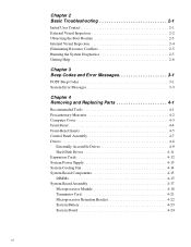
... Tools 4-1 Precautionary Measures 4-2 Computer Cover 4-3 Front Bezel 4-4 Front-Bezel Inserts 4-5 Control Panel Assembly 4-7 Drives 4-8 Externally Accessible Drives 4-9 Hard-Disk Drives 4-11 Expansion Cards 4-12 System Power Supply 4-13 System Cooling Fan 4-14 System Board Components 4-15 DIMMs 4-15 System Board Assembly 4-17 Microprocessor Module 4-18 Terminator Card 4-21 Microprocessor Retention Bracket 4-22...
... Tools 4-1 Precautionary Measures 4-2 Computer Cover 4-3 Front Bezel 4-4 Front-Bezel Inserts 4-5 Control Panel Assembly 4-7 Drives 4-8 Externally Accessible Drives 4-9 Hard-Disk Drives 4-11 Expansion Cards 4-12 System Power Supply 4-13 System Cooling Fan 4-14 System Board Components 4-15 DIMMs 4-15 System Board Assembly 4-17 Microprocessor Module 4-18 Terminator Card 4-21 Microprocessor Retention Bracket 4-22...

Service Manual
Page 5
... 4-3 Figure 4-3. Metal Insert Removal 4-6 Figure 4-6. Drive-Mounting Rails and Extensions Removal 4-10 Figure 4-10. Hard-Disk Drive Removal 4-11 Figure 4-11. DC Power Distribution 1-13 Figure 1-11. Computer Cover Removal 4-3 Figure 4-2. Front Bezel Removal 4-4 Figure 4-4. Power Supply Removal 4-13 vii Back/Left Side Internal View 1-5 Figure 1-5. Computer Orientation 1-2 Figure 1-2. Drive Hardware 4-8 Figure 4-8. DC...
... 4-3 Figure 4-3. Metal Insert Removal 4-6 Figure 4-6. Drive-Mounting Rails and Extensions Removal 4-10 Figure 4-10. Hard-Disk Drive Removal 4-11 Figure 4-11. DC Power Distribution 1-13 Figure 1-11. Computer Cover Removal 4-3 Figure 4-2. Front Bezel Removal 4-4 Figure 4-4. Power Supply Removal 4-13 vii Back/Left Side Internal View 1-5 Figure 1-5. Computer Orientation 1-2 Figure 1-2. Drive Hardware 4-8 Figure 4-8. DC...
Service Manual
Page 9
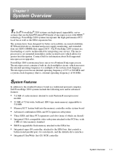
... the internal operating frequency to the EISA bus, that support ECC. The microprocessor(s) are mounted in a traditional personal computer, Dell PowerEdge 2200 systems include the following new and/or advanced features: • 512 KB of cache memory internal to each Pentium II microprocessor... and three PCI expansion-card slots (none of which allows for better serviceability, increased reliability, SCSI hard-disk drives, thermal and power supply monitoring, and extendeddata out (EDO) DIMMs that controls a bidirectional parallel port, two serial ports, and the diskette drive interface &#...
... the internal operating frequency to the EISA bus, that support ECC. The microprocessor(s) are mounted in a traditional personal computer, Dell PowerEdge 2200 systems include the following new and/or advanced features: • 512 KB of cache memory internal to each Pentium II microprocessor... and three PCI expansion-card slots (none of which allows for better serviceability, increased reliability, SCSI hard-disk drives, thermal and power supply monitoring, and extendeddata out (EDO) DIMMs that controls a bidirectional parallel port, two serial ports, and the diskette drive interface &#...

Service Manual
Page 12
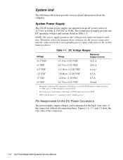
Front/Right Side Internal View system-board/ mounting plate assembly 1-4 Dell PowerEdge 2200 Systems Service Manual system power supply control panel assembly diskette drive CD-ROM drive third drive bay diskette controller cable power cables control panel cable SCSI cable system cooling fan front bezel internal hard-disk drive cage Figure 1-3.
Front/Right Side Internal View system-board/ mounting plate assembly 1-4 Dell PowerEdge 2200 Systems Service Manual system power supply control panel assembly diskette drive CD-ROM drive third drive bay diskette controller cable power cables control panel cable SCSI cable system cooling fan front bezel internal hard-disk drive cage Figure 1-3.

Service Manual
Page 13
... controller on the system board. The ECC feature provides more reliable memory and less downtime. capacity DIMMs installed in pairs. System Overview 1-5 power-supply selector switch AC power input connector I/O panel connectors externally accessible drive bays (3) SCSI hard-disk drive cage SCSI cable hard-disk-drive... power cables system board Figure 1-4. and 128-MB buffered, EDO-type DIMMs. The system board has four 168-pin DIMM sockets. The socket ...
... controller on the system board. The ECC feature provides more reliable memory and less downtime. capacity DIMMs installed in pairs. System Overview 1-5 power-supply selector switch AC power input connector I/O panel connectors externally accessible drive bays (3) SCSI hard-disk drive cage SCSI cable hard-disk-drive... power cables system board Figure 1-4. and 128-MB buffered, EDO-type DIMMs. The system board has four 168-pin DIMM sockets. The socket ...
Service Manual
Page 18
... mA 1 Maximum continuous DC output power should not exceed 170 W. 2 The total power of 115 VAC at 60 Hz or 230 VAC at the back (wire side) of the connectors. 1-10 Dell PowerEdge 2200 Systems Service Manual The system power supply provides the DC operating voltages and ...currents listed in Table 1-1. Pin Assignments for the DC Power Connectors The power-supply output voltages can operate from an AC power source of all voltages other than +...
... mA 1 Maximum continuous DC output power should not exceed 170 W. 2 The total power of 115 VAC at 60 Hz or 230 VAC at the back (wire side) of the connectors. 1-10 Dell PowerEdge 2200 Systems Service Manual The system power supply provides the DC operating voltages and ...currents listed in Table 1-1. Pin Assignments for the DC Power Connectors The power-supply output voltages can operate from an AC power source of all voltages other than +...

Service Manual
Page 19
... on the front panel is pressed, taking PSON# to indicate that all power-supply output voltages are within ranges specified in Table 1-1. Figure 1-6. -5 VDC (white) +5 VDC (red) common (black) +5 VDC (red) common (black) +5 VDC (red) common (black) not used (...) +5 VDC (red) common (black) -12 VDC (blue) common (black) PWRGOOD 2 (orange) +12 VDC (yellow) +5 VFP (purple) 1 Pin 11 - DC Power Connectors P2, P3, P4, P5, and P6 System Overview 1-11 DC Power Connector P1 1234 P2, P3, P5, P6 +12 VDC (yellow) common (black) common (black) +5 VDC (red) P4 12 34 +12...
... on the front panel is pressed, taking PSON# to indicate that all power-supply output voltages are within ranges specified in Table 1-1. Figure 1-6. -5 VDC (white) +5 VDC (red) common (black) +5 VDC (red) common (black) +5 VDC (red) common (black) not used (...) +5 VDC (red) common (black) -12 VDC (blue) common (black) PWRGOOD 2 (orange) +12 VDC (yellow) +5 VFP (purple) 1 Pin 11 - DC Power Connectors P2, P3, P4, P5, and P6 System Overview 1-11 DC Power Connector P1 1234 P2, P3, P5, P6 +12 VDC (yellow) common (black) common (black) +5 VDC (red) P4 12 34 +12...
Service Manual
Page 20
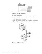
DC Power Connector P7 DC Power Distribution Figures 1-9 and 1-10 provide the following information about DC power distribution: • Power-supply connector identification • Power cable connections for diskette, tape, CD-ROM, and hard-disk drives • Power distribution to sockets and connectors on the system board P1 P4 P5 P7 P6 P3 P2 Figure 1-9. DC Power Cables 1-12 Dell PowerEdge 2200 Systems Service Manual P7 1 2 34 5 6 +3.3 VDC (blue/white) +3.3 VDC (blue/white) +3.3 VDC (blue/white) common (black) common (black) common (black) Figure 1-8.
DC Power Connector P7 DC Power Distribution Figures 1-9 and 1-10 provide the following information about DC power distribution: • Power-supply connector identification • Power cable connections for diskette, tape, CD-ROM, and hard-disk drives • Power distribution to sockets and connectors on the system board P1 P4 P5 P7 P6 P3 P2 Figure 1-9. DC Power Cables 1-12 Dell PowerEdge 2200 Systems Service Manual P7 1 2 34 5 6 +3.3 VDC (blue/white) +3.3 VDC (blue/white) +3.3 VDC (blue/white) common (black) common (black) common (black) Figure 1-8.

Service Manual
Page 21
... System Overview 1-13 keyboard controller system board +3 VDC system power supply PSON# +5 VFP +5 VDC -5 VDC +12 VDC -12 VDC P7 +3.3 VDC P1 POWER power management logic PWRGOOD PSON# +5 VFP +5 VDC -5 VDC +12 VDC -12 VDC RTC/ NVRAM POWER3V battery +3.3 VDC +5 VDC +12 VDC -12 VDC PCI4 through PCI6 +5 VDC -5 ...
... System Overview 1-13 keyboard controller system board +3 VDC system power supply PSON# +5 VFP +5 VDC -5 VDC +12 VDC -12 VDC P7 +3.3 VDC P1 POWER power management logic PWRGOOD PSON# +5 VFP +5 VDC -5 VDC +12 VDC -12 VDC RTC/ NVRAM POWER3V battery +3.3 VDC +5 VDC +12 VDC -12 VDC PCI4 through PCI6 +5 VDC -5 ...
Service Manual
Page 29
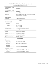
...-ROM drive access indicator green LED Video Video type ATI mach64 (264VT) PCI video controller with integrated VGA connector Video memory (standard 1 MB (not upgradable) Power DC power supply: Wattage 230 W Voltage 115 V at 60 Hz; 230 V at 50 Hz Backup battery 3.0-V CR2032 lithium coin cell Physical Height 44.45 cm (17.5 inches...
...-ROM drive access indicator green LED Video Video type ATI mach64 (264VT) PCI video controller with integrated VGA connector Video memory (standard 1 MB (not upgradable) Power DC power supply: Wattage 230 W Voltage 115 V at 60 Hz; 230 V at 50 Hz Backup battery 3.0-V CR2032 lithium coin cell Physical Height 44.45 cm (17.5 inches...
Service Manual
Page 33
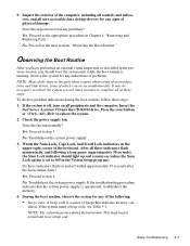
... and indications, some of which can occur simultaneously. Does the fan run normally? Troubleshoot the system power supply. 3. After all of beeps that the system power supply is not a beep code. Yes. Troubleshoot the system power supply. Yes. Insert the Dell Server Assistant CD into the CD-ROM drive. If the system emits a beep code, see Table...
... and indications, some of which can occur simultaneously. Does the fan run normally? Troubleshoot the system power supply. 3. After all of beeps that the system power supply is not a beep code. Yes. Troubleshoot the system power supply. Yes. Insert the Dell Server Assistant CD into the CD-ROM drive. If the system emits a beep code, see Table...

Service Manual
Page 34
... To perform the internal visual inspection, follow these indicators fails to work inside the computer, disconnect the power supply from the power source and the power supply cables from their sockets or connectors. vide status information. Does the menu appear? WARNING: While reseating ... "Running the System Diagnostics" found later in the inspection procedure. When you proceed with a metal surface on the chassis. 2-4 Dell PowerEdge 2200 Systems Service Manual Internal Visual Inspection CAUTION: Before you perform the visual inspection, refer to "System Features" in Chapter 1 to cool...
... To perform the internal visual inspection, follow these indicators fails to work inside the computer, disconnect the power supply from the power source and the power supply cables from their sockets or connectors. vide status information. Does the menu appear? WARNING: While reseating ... "Running the System Diagnostics" found later in the inspection procedure. When you proceed with a metal surface on the chassis. 2-4 Dell PowerEdge 2200 Systems Service Manual Internal Visual Inspection CAUTION: Before you perform the visual inspection, refer to "System Features" in Chapter 1 to cool...

Service Manual
Page 55
... the DC power cables from the AC power connector on the back of the power supply engage the retaining tabs on the bottom of the power supply. 2. Slide the power supply forward about ...an inch to record the connector number and plug location for each power cable. 3. Disconnect the AC power cable from the system board (see Figure 4-14), the externally accessible drives, and the hard-disk drives (see Figure 4-7). Remove the four power-supply mounting screws. 4. System Power Supply power supply power-supply mounting screws (4) AC power...
... the DC power cables from the AC power connector on the back of the power supply engage the retaining tabs on the bottom of the power supply. 2. Slide the power supply forward about ...an inch to record the connector number and plug location for each power cable. 3. Disconnect the AC power cable from the system board (see Figure 4-14), the externally accessible drives, and the hard-disk drives (see Figure 4-7). Remove the four power-supply mounting screws. 4. System Power Supply power supply power-supply mounting screws (4) AC power...
Service Manual
Page 81
... cooling fan removal, 4-14 system diagnostics, running, 2-5 system error messages list of, 3-3 system features, 1-1 system memory, 1-5 system power supply, 1-10 System Setup program Advanced menu, A-6 Boot Options submenu, A-5 Index 3 M memory, system, 1-5 messages, error, 3-3 microprocessor... cards, 1-6 POST beep codes, 3-1 power button, 1-3 POWER connector, 4-15 power indicator, 1-3 power supply about, 1-10 cables, 1-12 connectors, 1-10 DC voltage ranges, 1-10 illustrated, 1-12 power distribution diagram, 1-13 removal, 4-13 power supply switch, 1-5 POWER3V connector, 4-15 precautionary...
... cooling fan removal, 4-14 system diagnostics, running, 2-5 system error messages list of, 3-3 system features, 1-1 system memory, 1-5 system power supply, 1-10 System Setup program Advanced menu, A-6 Boot Options submenu, A-5 Index 3 M memory, system, 1-5 messages, error, 3-3 microprocessor... cards, 1-6 POST beep codes, 3-1 power button, 1-3 POWER connector, 4-15 power indicator, 1-3 power supply about, 1-10 cables, 1-12 connectors, 1-10 DC voltage ranges, 1-10 illustrated, 1-12 power distribution diagram, 1-13 removal, 4-13 power supply switch, 1-5 POWER3V connector, 4-15 precautionary...


