
Information Update
Page 1
...2724 NOTE: The PowerConnect 27xx switches are shipped as a Web-managed switch. Enabling Web-Managed Mode After powering up as unmanaged switches. When changing to the Web-managed mode, the switch is reset to change the IP address of the switch, see "Viewing System IP Address...of each switch that you can update the switch IP Address either: • Manually, or • By enabling DHCP Addressing NOTE: To update the IP address, see the Dell PowerConnect 27xx Systems User's Guide. www.dell.com | support.dell.com Enabling Web-Managed Mode for changing the password....
...2724 NOTE: The PowerConnect 27xx switches are shipped as a Web-managed switch. Enabling Web-Managed Mode After powering up as unmanaged switches. When changing to the Web-managed mode, the switch is reset to change the IP address of the switch, see "Viewing System IP Address...of each switch that you can update the switch IP Address either: • Manually, or • By enabling DHCP Addressing NOTE: To update the IP address, see the Dell PowerConnect 27xx Systems User's Guide. www.dell.com | support.dell.com Enabling Web-Managed Mode for changing the password....

Getting Started Guide
Page 12
... from the network administrator before completely booting. You can download the release notes from the Dell Support website at support.dell.com. NOTE: Obtain the following assumptions: • The PowerConnect device is configured with the system specific configuration. Setup of the management interface is not ...assigned to the VLAN 1 interface through which the device is to be managed • The IP subnet mask for the network • The default gateway (next hop router) IP address for this product. NOTE: Before proceeding, read the release notes for configuring the default route....
... from the network administrator before completely booting. You can download the release notes from the Dell Support website at support.dell.com. NOTE: Obtain the following assumptions: • The PowerConnect device is configured with the system specific configuration. Setup of the management interface is not ...assigned to the VLAN 1 interface through which the device is to be managed • The IP subnet mask for the network • The default gateway (next hop router) IP address for this product. NOTE: Before proceeding, read the release notes for configuring the default route....

Getting Started Guide
Page 13
... started guide provides information on your documenatation CD. To do so, enter the IP address of the device in the URL field of the switch. For more information on the management capabilities of the switch, please refer the PowerConnect 27xx Series User's Guide found on the steps necessary for basic setup of a web...: The web management interface supports the following web browsers: Microsoft Internet Explorer 6.x or above and Mozilla Version 1.7.x or above. 2 In the Web user interface, Click IP Addressing.
... started guide provides information on your documenatation CD. To do so, enter the IP address of the device in the URL field of the switch. For more information on the management capabilities of the switch, please refer the PowerConnect 27xx Series User's Guide found on the steps necessary for basic setup of a web...: The web management interface supports the following web browsers: Microsoft Internet Explorer 6.x or above and Mozilla Version 1.7.x or above. 2 In the Web user interface, Click IP Addressing.

User's Guide
Page 5
Resetting the Device 41 Displaying Configuration on Demand 42 6 Configuring System Information Defining Switch Information 43 Viewing the Switch Status 43 Viewing System IP Address 44 Defining Interface Configuration 47 Viewing Jumbo Frames 49 Creating VLAN Membership 50 Defining VLAN Interface Settings 51 Configuring LAG Membership 52 Managing System Files ...
Resetting the Device 41 Displaying Configuration on Demand 42 6 Configuring System Information Defining Switch Information 43 Viewing the Switch Status 43 Viewing System IP Address 44 Defining Interface Configuration 47 Viewing Jumbo Frames 49 Creating VLAN Membership 50 Defining VLAN Interface Settings 51 Configuring LAG Membership 52 Managing System Files ...

User's Guide
Page 9
...so that the HOL blocking prevention mechanism is active at all ports is done by removing the IP address to OFF. This is pressed, the switch enters Managed Mode default configuration with the default IP address of 192.168.2.1. • Managed Mode - This is set to the switch so that...From Unmanaged Mode, when the Managed Mode button is pressed, the switch enters Unmanaged Mode. • Secure Mode (PowerConnect 2748 only) - The switch does not have an IP address, nor is unavailable for the same egress port resources. Secure Mode works by the user configuring the switch in Managed ...
...so that the HOL blocking prevention mechanism is active at all ports is done by removing the IP address to OFF. This is pressed, the switch enters Managed Mode default configuration with the default IP address of 192.168.2.1. • Managed Mode - This is set to the switch so that...From Unmanaged Mode, when the Managed Mode button is pressed, the switch enters Unmanaged Mode. • Secure Mode (PowerConnect 2748 only) - The switch does not have an IP address, nor is unavailable for the same egress port resources. Secure Mode works by the user configuring the switch in Managed ...

User's Guide
Page 12
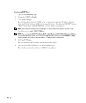
...DHCP Clients DHCP (Dynamic Host Configuration Protocol) enables additional setup parameters to define various services for classifying traffic. Class of Service (CoS) Features The PowerConnect 2708/2716/2724/2748 system enables users to be received from physical link disruption • Higher bandwidth connections • Improved bandwidth granularity • High bandwidth server connectivity...(VLANs) Port-based VLANs classify incoming packets to all ports on the use of multiple priority queues for traffic classes of ports with a TFTP server IP address and a download file name.
...DHCP Clients DHCP (Dynamic Host Configuration Protocol) enables additional setup parameters to define various services for classifying traffic. Class of Service (CoS) Features The PowerConnect 2708/2716/2724/2748 system enables users to be received from physical link disruption • Higher bandwidth connections • Improved bandwidth granularity • High bandwidth server connectivity...(VLANs) Port-based VLANs classify incoming packets to all ports on the use of multiple priority queues for traffic classes of ports with a TFTP server IP address and a download file name.

User's Guide
Page 21
... to Admin, and the password is not configured (appears blank), with Read/Write privilege. • The DHCP client is set as the switch IP address. • Subnet mask changes to 255.255.255.0 • Graphical User Interface (GUI) login user name changes to factory default settings. SFP...The port is occurring. The port is for changing between Managed Mode and Unmanaged (or Secure) Mode. Table 2-5. Managed Mode Button The PowerConnect 2708/2716/2724/2748 has a Managed Mode push button on the front panel. From Unmanaged or Secure Mode (2748 only), pressing the Managed Mode button ...
... to Admin, and the password is not configured (appears blank), with Read/Write privilege. • The DHCP client is set as the switch IP address. • Subnet mask changes to 255.255.255.0 • Graphical User Interface (GUI) login user name changes to factory default settings. SFP...The port is occurring. The port is for changing between Managed Mode and Unmanaged (or Secure) Mode. Table 2-5. Managed Mode Button The PowerConnect 2708/2716/2724/2748 has a Managed Mode push button on the front panel. From Unmanaged or Secure Mode (2748 only), pressing the Managed Mode button ...
User's Guide
Page 34
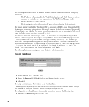
...following login screen is displayed when the device is ready to be configured. The switch supports the following steps: 1 Open the IP Addressing window in Unmanaged Mode. The default IP address is 192.168.2.1, the default User Name is 'admin', and the default password is left blank. The device must be ... EWS. 34 To change to Managed Mode, the device must be changed to Managed Mode before configuring the device: • The IP address to be assigned to the VLAN 1 interface through which the device is to Web-based input (including menu selections, mouse clicks, etc.).
...following login screen is displayed when the device is ready to be configured. The switch supports the following steps: 1 Open the IP Addressing window in Unmanaged Mode. The default IP address is 192.168.2.1, the default User Name is 'admin', and the default password is left blank. The device must be ... EWS. 34 To change to Managed Mode, the device must be changed to Managed Mode before configuring the device: • The IP address to be assigned to the VLAN 1 interface through which the device is to Web-based input (including menu selections, mouse clicks, etc.).
User's Guide
Page 35
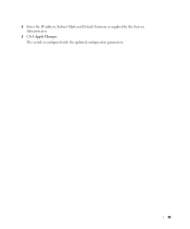
The switch is configured with the updated configuration parameters. 35 2 Enter the IP address, Subnet Mask and Default Gateway as supplied by the System Administrator. 3 Click Apply Changes.
The switch is configured with the updated configuration parameters. 35 2 Enter the IP address, Subnet Mask and Default Gateway as supplied by the System Administrator. 3 Click Apply Changes.
User's Guide
Page 39
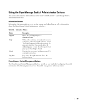
... Button Support Help About Log Out Description Opens the Dell Support page at support.dell.com. Contains the version and build number and Dell copyright information. Information Buttons Information buttons provide access to on the Dell™ PowerConnect™ OpenManage Switch Administrator interface. For example, if the IP Addressing page is clicked. Logs out of configuring the...
... Button Support Help About Log Out Description Opens the Dell Support page at support.dell.com. Contains the version and build number and Dell copyright information. Information Buttons Information buttons provide access to on the Dell™ PowerConnect™ OpenManage Switch Administrator interface. For example, if the IP Addressing page is clicked. Logs out of configuring the...
User's Guide
Page 40
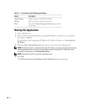
... enter a user name and password. For information about assigning an IP address to the Ethernet Switch. NOTE: Passwords are both case-sensitive and alphanumeric. 4 Click OK. PowerConnect Switch Management Buttons Button Apply Changes Refresh Print Description Applies changes to ...the Ethernet Switch, see "Managed Mode Button". Prints the Network Management System page or table information. The Dell PowerConnect OpenManage Switch Administrator home page ...
... enter a user name and password. For information about assigning an IP address to the Ethernet Switch. NOTE: Passwords are both case-sensitive and alphanumeric. 4 Click OK. PowerConnect Switch Management Buttons Button Apply Changes Refresh Print Description Applies changes to ...the Ethernet Switch, see "Managed Mode Button". Prints the Network Management System page or table information. The Dell PowerConnect OpenManage Switch Administrator home page ...
User's Guide
Page 44
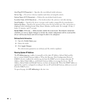
...device's unique serial number, assigned by the manufacturer. For example, 41 days, 2 hours, 22 minutes, and 15 seconds. The IP Address, Subnet Mask and Default Gateway are defined, and the switch is currently running. Specifies the user-defined switch reference. Defines the user-...defined switch name. Secure Mode (2748 only) - Viewing System IP Address The IP Addressing page enables to manually set dynamically. To open the page, click IP Addressing in the following format: Days, Hours, Minutes, and Seconds. Serial Number - Specifies the ...
...device's unique serial number, assigned by the manufacturer. For example, 41 days, 2 hours, 22 minutes, and 15 seconds. The IP Address, Subnet Mask and Default Gateway are defined, and the switch is currently running. Specifies the user-defined switch reference. Defines the user-...defined switch name. Secure Mode (2748 only) - Viewing System IP Address The IP Addressing page enables to manually set dynamically. To open the page, click IP Addressing in the following format: Days, Hours, Minutes, and Seconds. Serial Number - Specifies the ...

User's Guide
Page 45
... the switch. 5 Reconnect the device with the new IP Address. This field enables the DHCP client. DHCP IP Address - Activates the IP Address, Subnet Mask Address, and Default Gateway Address, received from the DHCP server. Updating Static IP Address 1 Open the IP Addressing page. 2 Verify that the DHCP field is Disable. IP Address - Specifies the static IP Address currently assigned to the device. Specifies the static...
... the switch. 5 Reconnect the device with the new IP Address. This field enables the DHCP client. DHCP IP Address - Activates the IP Address, Subnet Mask Address, and Default Gateway Address, received from the DHCP server. Updating Static IP Address 1 Open the IP Addressing page. 2 Verify that the DHCP field is Disable. IP Address - Specifies the static IP Address currently assigned to the device. Specifies the static...
User's Guide
Page 46
... device. NOTE: The displayed values are displayed. NOTE: The new dynamic DHCP IP Address, DHCP Subnet Mask, and DHCP Default Gateway Address received from the DHCP server to assign a new dynamic IP Address, Subnet Mask, and Default Gateway Address to the new DHCP client address. 46 The switch is clicked on. Record the updated dynamic fields. 4 Check...
... device. NOTE: The displayed values are displayed. NOTE: The new dynamic DHCP IP Address, DHCP Subnet Mask, and DHCP Default Gateway Address received from the DHCP server to assign a new dynamic IP Address, Subnet Mask, and Default Gateway Address to the new DHCP client address. 46 The switch is clicked on. Record the updated dynamic fields. 4 Check...
User's Guide
Page 55
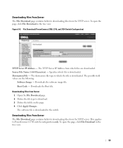
...files from the TFTP server. To open the page, click File Download in the tree view. 55 File Download (PowerConnect 2708, 2716, and 2724 Switch Configuration) TFTP Server IP Address - Source File Name (1-64 Characters) - The software file is downloaded. Boot Code - Downloading Files from which... Click Apply Changes. Downloading Files From Server The File Download page contains fields for downloading files from the TFTP server. The TFTP Server IP Address from Server 1 Open the File Download page. 2 Define the file type to the switch. Downloads the software image file. Figure ...
...files from the TFTP server. To open the page, click File Download in the tree view. 55 File Download (PowerConnect 2708, 2716, and 2724 Switch Configuration) TFTP Server IP Address - Source File Name (1-64 Characters) - The software file is downloaded. Boot Code - Downloading Files from which... Click Apply Changes. Downloading Files From Server The File Download page contains fields for downloading files from the TFTP server. The TFTP Server IP Address from Server 1 Open the File Download page. 2 Define the file type to the switch. Downloads the software image file. Figure ...
User's Guide
Page 56
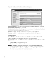
File Download (PowerConnect 2748 Switch Configuration) Firmware Download - The Firmware file is downloaded. The Configuration file is downloaded. Enables initiating an image download via HTTP - Download via the TFTP server. Firmware Download Server IP Address - Source File Name (1-159 Characters)- The possible ... image. During the image file download, a dialog box opens which the firmware files are : Software Image - The Server IP Address from which displays the download progress. Indicates the file to reset the device following the download. Download via the HTTP protocol....
File Download (PowerConnect 2748 Switch Configuration) Firmware Download - The Firmware file is downloaded. The Configuration file is downloaded. Enables initiating an image download via HTTP - Download via the TFTP server. Firmware Download Server IP Address - Source File Name (1-159 Characters)- The possible ... image. During the image file download, a dialog box opens which the firmware files are : Software Image - The Server IP Address from which displays the download progress. Indicates the file to reset the device following the download. Download via the HTTP protocol....
User's Guide
Page 57
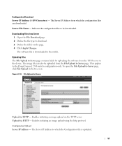
... Define the file type to Server Upload via TFTP - To open the File Upload to the device. The Server IP Address to the switch. Configuration Download Server IP Address (1-159 Characters) - Source File Name - The software file is downloaded to which the configuration files are downloaded. File...page. Figure 6-10. The image file can also be downloaded. Upload via the TFTP server. The Server IP Address from the File Upload to the PowerConnect 2748 switch configuration only. Indicates the configuration files to be uploaded from which the Configuration file is uploaded....
... Define the file type to Server Upload via TFTP - To open the File Upload to the device. The Server IP Address to the switch. Configuration Download Server IP Address (1-159 Characters) - Source File Name - The software file is downloaded to which the configuration files are downloaded. File...page. Figure 6-10. The image file can also be downloaded. Upload via the TFTP server. The Server IP Address from the File Upload to the PowerConnect 2748 switch configuration only. Indicates the configuration files to be uploaded from which the Configuration file is uploaded....
User's Guide
Page 59
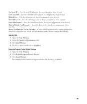
Uses the saved IP address for device configuration, when selected. Copying Files 1 Open the Copy Files page. 2 Define the Source and Destination fields. 3 Click Apply Changes. 4 The file is copied, ... company factory default settings are restored, and the device is updated. Use Saved IP - Restore Configuration Factory Defaults - Restoring Company Factory Default Settings 1 Open the Copy Files page. 2 Click Restore Company Factory Defaults 3 Click Apply Changes. Uses the current IP address for device configuration, when selected. Uses the default password for device configuration...
Uses the saved IP address for device configuration, when selected. Copying Files 1 Open the Copy Files page. 2 Define the Source and Destination fields. 3 Click Apply Changes. 4 The file is copied, ... company factory default settings are restored, and the device is updated. Use Saved IP - Restore Configuration Factory Defaults - Restoring Company Factory Default Settings 1 Open the Copy Files page. 2 Click Restore Company Factory Defaults 3 Click Apply Changes. Uses the current IP address for device configuration, when selected. Uses the default password for device configuration...
User's Guide
Page 77
Bandwidth Bandwidth specifies the amount of data that receive broadcast frames originating from any Ethernet switch module within a designated set. Enables a workstation to discover its IP address, an IP address of a switch module. Routers bind Broadcast domains, because routers do not forward broadcast frames. Best Effort Traffic is assigned to all ports on a network, or...
Bandwidth Bandwidth specifies the amount of data that receive broadcast frames originating from any Ethernet switch module within a designated set. Enables a workstation to discover its IP address, an IP address of a switch module. Routers bind Broadcast domains, because routers do not forward broadcast frames. Best Effort Traffic is assigned to all ports on a network, or...

User's Guide
Page 80
... Layer or MAC Layer. Packets destined for that address are forwarded to the correct port. IP Internet Protocol. IP Address Internet Protocol Address. Aggregates ports or VLANs into a single virtual port or VLAN. The MAC Address is recorded. Contains the physical address of packets and there addressing method. MAC Address Learning MAC Address Learning characterizes a learning bridge, in fewer frames...
... Layer or MAC Layer. Packets destined for that address are forwarded to the correct port. IP Internet Protocol. IP Address Internet Protocol Address. Aggregates ports or VLANs into a single virtual port or VLAN. The MAC Address is recorded. Contains the physical address of packets and there addressing method. MAC Address Learning MAC Address Learning characterizes a learning bridge, in fewer frames...


