
Information Update
Page 1
... factory default settings. NOTE: For security reasons, we recommend that has been set up your switch according to the Web-managed mode, the switch is advisable to Web-managed mode and the Managed Mode LED will be illuminated green. NOTE: The Managed Mode button is recessed to take advantage of the management features of the switch, see "Initial Configuration" in Dell PowerConnect 27xx Systems User's Guide Logging In And Changing Switch IP Address and Password You can configure the switch using a Web interface. When changing to the instructions...
... factory default settings. NOTE: For security reasons, we recommend that has been set up your switch according to the Web-managed mode, the switch is advisable to Web-managed mode and the Managed Mode LED will be illuminated green. NOTE: The Managed Mode button is recessed to take advantage of the management features of the switch, see "Initial Configuration" in Dell PowerConnect 27xx Systems User's Guide Logging In And Changing Switch IP Address and Password You can configure the switch using a Web interface. When changing to the instructions...

Getting Started Guide
Page 12
...: • The IP address to be assigned to the VLAN 1 interface through which the device is to configure the device with the pre configured default IP (192.168.2.1) and subnet mask (255.255.255.0). • The PowerConnect device booted successfully. Without specific configuration, the device functions with the default settings, as an unmanaged switch. To use the management functions, refer the configuration options and details in the User's Guide.
...: • The IP address to be assigned to the VLAN 1 interface through which the device is to configure the device with the pre configured default IP (192.168.2.1) and subnet mask (255.255.255.0). • The PowerConnect device booted successfully. Without specific configuration, the device functions with the default settings, as an unmanaged switch. To use the management functions, refer the configuration options and details in the User's Guide.

User's Guide
Page 3
...Gigabit Ethernet Ports 8 24 1-Gigabit Ethernet Ports + 2 SFP Combo ports 8 48 1-Gigabit Ethernet Ports 8 Features 9 General Features 9 MAC Address Supported Features 11 Layer 2 Features 11 VLAN Supported Features 12 Class of Service (CoS) Features 12 Ethernet Switch Management Features 13 Port Default Settings 13 2 Hardware Description Switch Port Configurations 15 PowerConnect 2708/2716/2724/2748 Front Panel Port Description . . . . 15 Physical Dimensions 19 LED Definitions 19 Power LED 19 Managed Mode LED 19 Fan LED (2748 only 20 Port LEDs 20 Managed Mode Button 21 Switch...
...Gigabit Ethernet Ports 8 24 1-Gigabit Ethernet Ports + 2 SFP Combo ports 8 48 1-Gigabit Ethernet Ports 8 Features 9 General Features 9 MAC Address Supported Features 11 Layer 2 Features 11 VLAN Supported Features 12 Class of Service (CoS) Features 12 Ethernet Switch Management Features 13 Port Default Settings 13 2 Hardware Description Switch Port Configurations 15 PowerConnect 2708/2716/2724/2748 Front Panel Port Description . . . . 15 Physical Dimensions 19 LED Definitions 19 Power LED 19 Managed Mode LED 19 Fan LED (2748 only 20 Port LEDs 20 Managed Mode Button 21 Switch...
User's Guide
Page 7
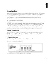
...Hubs (Wireless LAN Access Points) • Routers The PowerConnect devices are designed to medium business that requires high performance network connectivity along with advanced web management features.The PowerConnect management features are primarily for installing, configuring and maintaining the PowerConnect 2708, PowerConnect 2716, PowerConnect 2724, and PowerConnect 2748 Webmanaged Gigabit Ethernet switches. System Description This section describes the hardware configurations of the PowerConnect 2708, PowerConnect 2716, PowerConnect 2724, and PowerConnect 2748. These PowerConnect...
...Hubs (Wireless LAN Access Points) • Routers The PowerConnect devices are designed to medium business that requires high performance network connectivity along with advanced web management features.The PowerConnect management features are primarily for installing, configuring and maintaining the PowerConnect 2708, PowerConnect 2716, PowerConnect 2724, and PowerConnect 2748 Webmanaged Gigabit Ethernet switches. System Description This section describes the hardware configurations of the PowerConnect 2708, PowerConnect 2716, PowerConnect 2724, and PowerConnect 2748. These PowerConnect...

User's Guide
Page 9
... Managed Mode button. By default, the device is configured so that it prevents users from making any further configuration changes to Secure Mode via the web interface. In Secure Mode the switch retains configuration through power cycles. The switch does not have an IP address, nor is set to links operating at Half Duplex only. 9 HOL blocking queues packets, and the packets at the head of the queue are forwarded before packets at all ports...
... Managed Mode button. By default, the device is configured so that it prevents users from making any further configuration changes to Secure Mode via the web interface. In Secure Mode the switch retains configuration through power cycles. The switch does not have an IP address, nor is set to links operating at Half Duplex only. 9 HOL blocking queues packets, and the packets at the head of the queue are forwarded before packets at all ports...

User's Guide
Page 11
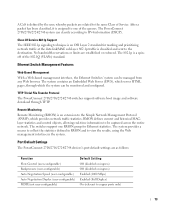
... source ports. Users can specify which no traffic is not performed (where frames are forwarded based on both the network links and the host operating system. 11 Layer 2 Features Port Mirroring The port mirroring mechanism monitors and mirrors network traffic by the switch. All nodes connected to these ports accept and attempt to a monitoring port. Auto-Learning MAC Addresses The switch enables MAC address auto-learning from overflowing. Addresses are stored in the Bridging Table. Storm Control Storm Control enables limiting the amount of Multicast and Broadcast frames...
... source ports. Users can specify which no traffic is not performed (where frames are forwarded based on both the network links and the host operating system. 11 Layer 2 Features Port Mirroring The port mirroring mechanism monitors and mirrors network traffic by the switch. All nodes connected to these ports accept and attempt to a monitoring port. Auto-Learning MAC Addresses The switch enables MAC address auto-learning from overflowing. Addresses are stored in the Bridging Table. Storm Control Storm Control enables limiting the amount of Multicast and Broadcast frames...

User's Guide
Page 12
... supporting bandwidth management and control is an on-going process. BootP and DHCP Clients DHCP (Dynamic Host Configuration Protocol) enables additional setup parameters to be grouped in the same VLAN. Class of Service (CoS) Features The PowerConnect 2708/2716/2724/2748 system enables users to VLANs based on their ingress port. Link Aggregation The PowerConnect 2708/2716/2724/2748 switches support up to four member ports to provide the switch system with a TFTP server IP address and a download file...
... supporting bandwidth management and control is an on-going process. BootP and DHCP Clients DHCP (Dynamic Host Configuration Protocol) enables additional setup parameters to be grouped in the same VLAN. Class of Service (CoS) Features The PowerConnect 2708/2716/2724/2748 system enables users to VLANs based on their ingress port. Link Aggregation The PowerConnect 2708/2716/2724/2748 switches support up to four member ports to provide the switch system with a TFTP server IP address and a download file...
User's Guide
Page 13
...(VLANs) standard. TFTP Trivial File Transfer Protocol The PowerConnect 2708/2716/2724/2748 switches support software boot image and software download through which provides network traffic statistics. No bandwidth reservations or limits are as follows: Function Flow Control (user-configurable) Backpressure (user-configurable) Auto Negotiation Speed (user-configurable) Auto Negotiation Duplex (user-configurable) MDIX (not user-configurable) Default Setting Off (disabled on ingress) Off (disabled on ingress) Enabled (1000 Mbps) Enabled (Full Duplex) On (relevant to copper ports only...
...(VLANs) standard. TFTP Trivial File Transfer Protocol The PowerConnect 2708/2716/2724/2748 switches support software boot image and software download through which provides network traffic statistics. No bandwidth reservations or limits are as follows: Function Flow Control (user-configurable) Backpressure (user-configurable) Auto Negotiation Speed (user-configurable) Auto Negotiation Duplex (user-configurable) MDIX (not user-configurable) Default Setting Off (disabled on ingress) Off (disabled on ingress) Enabled (1000 Mbps) Enabled (Full Duplex) On (relevant to copper ports only...

User's Guide
Page 15
.... 2 Hardware Description Switch Port Configurations PowerConnect 2708/2716/2724/2748 Front Panel Port Description The Dell™ PowerConnect™ 2708, 2716, 2724 and 2748 switches use 10/100/1000BASE-T ports on the front panel, restores the device's default settings configuration. 15 On the left to a network. These ports support autonegotiation, duplex mode (Half or Full duplex), and flow control. Figure 2-1. The following figures illustrate the front panels and back panels of the front panel is powered...
.... 2 Hardware Description Switch Port Configurations PowerConnect 2708/2716/2724/2748 Front Panel Port Description The Dell™ PowerConnect™ 2708, 2716, 2724 and 2748 switches use 10/100/1000BASE-T ports on the front panel, restores the device's default settings configuration. 15 On the left to a network. These ports support autonegotiation, duplex mode (Half or Full duplex), and flow control. Figure 2-1. The following figures illustrate the front panels and back panels of the front panel is powered...

User's Guide
Page 21
...port is for changing between Managed Mode and Unmanaged (or Secure) Mode. The port is rebooted. 21 Table 2-5. From Unmanaged or Secure Mode (2748 only), pressing the Managed Mode button causes: • Factory default configuration (192.168.2.1) is set as the switch IP address. • Subnet mask changes to 255.255.255.0 • Graphical User Interface (GUI) login user name changes to factory default settings. RJ-45 Copper based 10/100/ 1000BASE-T LED Indications LED Color Left LED Green Static Green Flashing Amber Static Amber Flashing Off Right LED Green Static...
...port is for changing between Managed Mode and Unmanaged (or Secure) Mode. The port is rebooted. 21 Table 2-5. From Unmanaged or Secure Mode (2748 only), pressing the Managed Mode button causes: • Factory default configuration (192.168.2.1) is set as the switch IP address. • Subnet mask changes to 255.255.255.0 • Graphical User Interface (GUI) login user name changes to factory default settings. RJ-45 Copper based 10/100/ 1000BASE-T LED Indications LED Color Left LED Green Static Green Flashing Amber Static Amber Flashing Off Right LED Green Static...
User's Guide
Page 26
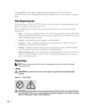
... as radio transmitters, broadcast amplifiers, power lines, and fluorescent lighting fixtures. • Ambient Requirements - The chapter "Starting and Configuring the Dell™PowerConnect™ 2708/2716/2724/2748 for cabling, power connections, and ventilation. • Cabling - There are present inside these parts, contact a service technician. 26 If you suspect a problem with different power feeders. • General - to Managed Mode. The device is routed to avoid sources of damage...
... as radio transmitters, broadcast amplifiers, power lines, and fluorescent lighting fixtures. • Ambient Requirements - The chapter "Starting and Configuring the Dell™PowerConnect™ 2708/2716/2724/2748 for cabling, power connections, and ventilation. • Cabling - There are present inside these parts, contact a service technician. 26 If you suspect a problem with different power feeders. • General - to Managed Mode. The device is routed to avoid sources of damage...
User's Guide
Page 34
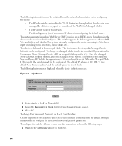
... default settings), it can be monitored and configured. When the Managed Mode LED stays lit, the switch is ready to be configured. The default IP address is 192.168.2.1, the default User Name is 'admin', and the default password is first connected: Figure 4-1. On first deployment of the VLAN 1 in Unmanaged Mode (Managed Mode LED has stopped blinking and is off). To configure the switch with new configuration parameters. The switch reboots and the Managed Mode LED blinks for configuring the default route. Login Screen 1 Enter admin...
... default settings), it can be monitored and configured. When the Managed Mode LED stays lit, the switch is ready to be configured. The default IP address is 192.168.2.1, the default User Name is 'admin', and the default password is first connected: Figure 4-1. On first deployment of the VLAN 1 in Unmanaged Mode (Managed Mode LED has stopped blinking and is off). To configure the switch with new configuration parameters. The switch reboots and the Managed Mode LED blinks for configuring the default route. Login Screen 1 Enter admin...
User's Guide
Page 39
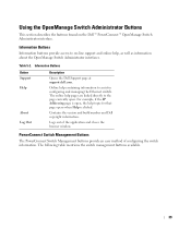
... browser window. Online help containing information to on the Dell™ PowerConnect™ OpenManage Switch Administrator interface. Information Buttons Information buttons provide access to assist in configuring and managing the Ethernet switch. Table 5-2. For example, if the IP Addressing page is clicked. Using the OpenManage Switch Administrator Buttons This section describes the buttons found on -line support and online help, as well as information about the OpenManage Switch Administrator interfaces. Logs out of configuring the switch...
... browser window. Online help containing information to on the Dell™ PowerConnect™ OpenManage Switch Administrator interface. Information Buttons Information buttons provide access to assist in configuring and managing the Ethernet switch. Table 5-2. For example, if the IP Addressing page is clicked. Using the OpenManage Switch Administrator Buttons This section describes the buttons found on -line support and online help, as well as information about the OpenManage Switch Administrator interfaces. Logs out of configuring the switch...
User's Guide
Page 44
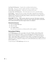
System Up Time- The system time is displayed in the tree view. 44 Secure Mode (2748 only) - As soon as Apply Changes is unchecked (disabled). The switch status parameters are then set the static IP Address, Subnet Mask and the device's static Default Gateway Address. When the Dynamic Host Configuration Protocol (DHCP) client is updated. The IP Address, Subnet Mask and Default Gateway are defined, and the switch is enabled, the switch requests from the DHCP server. System...
System Up Time- The system time is displayed in the tree view. 44 Secure Mode (2748 only) - As soon as Apply Changes is unchecked (disabled). The switch status parameters are then set the static IP Address, Subnet Mask and the device's static Default Gateway Address. When the Dynamic Host Configuration Protocol (DHCP) client is updated. The IP Address, Subnet Mask and Default Gateway are defined, and the switch is enabled, the switch requests from the DHCP server. System...

User's Guide
Page 48
... rate, duplex mode and flow control capacity to its partner (Auto Negotiation has to be used to the congested output device, when the number of flow control on the port. The possible statuses are On or Off. Current Advertisement - The receiving port can be enabled or disabled by prohibiting transmission from sending packets. The Flow Control mechanism enables lower speed devices to an end station, a straight through Ethernet cable can be enabled or disabled...
... rate, duplex mode and flow control capacity to its partner (Auto Negotiation has to be used to the congested output device, when the number of flow control on the port. The possible statuses are On or Off. Current Advertisement - The receiving port can be enabled or disabled by prohibiting transmission from sending packets. The Flow Control mechanism enables lower speed devices to an end station, a straight through Ethernet cable can be enabled or disabled...
User's Guide
Page 59
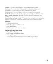
... address for device configuration, when selected. Saves the currently configured device user and password, when selected. Reset to the default user and password, when selected. When selected, specifies that the factory configuration default files should be reset. The company factory default settings are restored, and the device is updated. Default Password - Uses the default password for device configuration, when selected. Restoring Company Factory Default Settings 1 Open the Copy Files page. 2 Click Restore Company Factory Defaults 3 Click Apply Changes. Restore Configuration Factory...
... address for device configuration, when selected. Saves the currently configured device user and password, when selected. Reset to the default user and password, when selected. When selected, specifies that the factory configuration default files should be reset. The company factory default settings are restored, and the device is updated. Default Password - Uses the default password for device configuration, when selected. Restoring Company Factory Default Settings 1 Open the Copy Files page. 2 Click Restore Company Factory Defaults 3 Click Apply Changes. Restore Configuration Factory...

User's Guide
Page 64
..., click Port Mirroring in the tree view. The source port network traffic remains active, but no mirroring session takes place on the page. 3 Click Apply Changes. The parameters of both Tx and Rx. The test is Tx, Rx, or both source port and the destination port. Status - Indicates whether the source port is performed and the Optical Transceiver Diagnostics test table opens. When checked, it...
..., click Port Mirroring in the tree view. The source port network traffic remains active, but no mirroring session takes place on the page. 3 Click Apply Changes. The parameters of both Tx and Rx. The test is Tx, Rx, or both source port and the destination port. Status - Indicates whether the source port is performed and the Optical Transceiver Diagnostics test table opens. When checked, it...
User's Guide
Page 81
... example parts of a single packet to another IP address and waits for end stations. Port Speed Indicates port speed of the Data Link Control (DTL) layer. MAC Layer A sub-layer of the port. Port speeds include: • Ethernet 10 Mbps • Fast Ethernet 100Mbps • Gigabit Ethernet 1000 Mbps Protocol 81 Managed Mode Provides switch management through a web interface, and maintains the device configuration through power cycles. Port Mirroring Monitors and mirrors network traffic by forwarding copies of information for hubs and switches. Verifies if a specific IP address...
... example parts of a single packet to another IP address and waits for end stations. Port Speed Indicates port speed of the Data Link Control (DTL) layer. MAC Layer A sub-layer of the port. Port speeds include: • Ethernet 10 Mbps • Fast Ethernet 100Mbps • Gigabit Ethernet 1000 Mbps Protocol 81 Managed Mode Provides switch management through a web interface, and maintains the device configuration through power cycles. Port Mirroring Monitors and mirrors network traffic by forwarding copies of information for hubs and switches. Verifies if a specific IP address...

User's Guide
Page 83
... Ethernet switch modules with embedded SNMP agents. Router A Ethernet switch module that share a common address component. S Server A central computer that share a prefix are transmitted and received in a subnet address. Services may include file storage and access to be collected from a single workstation. Subnet Mask Used to separate networks. Provides network information to applications. Manages LANs. Subnet Sub-network. Enables two hosts to other computers on a network. Routers operate at a Layer 3 level. Switches support any packet protocol type. Routers forward...
... Ethernet switch modules with embedded SNMP agents. Router A Ethernet switch module that share a common address component. S Server A central computer that share a prefix are transmitted and received in a subnet address. Services may include file storage and access to be collected from a single workstation. Subnet Mask Used to separate networks. Provides network information to applications. Manages LANs. Subnet Sub-network. Enables two hosts to other computers on a network. Routers operate at a Layer 3 level. Switches support any packet protocol type. Routers forward...
User's Guide - Addendum
Page 2
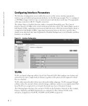
... appropriate cable type connection is forwarded through software reduce the amount of the physical LAN segment to set at Disable, and Flow Control is 10 Mbps as the actual synchronized interface speed. The Current Interface Speed is set the various interface parameters, interface type and additional operational attributes. VLANs managed through the port. Portbased VLANs are comprised of a set of ports that combine user stations and network devices into a single brodcast domain, regardless of time network changes, additions...
... appropriate cable type connection is forwarded through software reduce the amount of the physical LAN segment to set at Disable, and Flow Control is 10 Mbps as the actual synchronized interface speed. The Current Interface Speed is set the various interface parameters, interface type and additional operational attributes. VLANs managed through the port. Portbased VLANs are comprised of a set of ports that combine user stations and network devices into a single brodcast domain, regardless of time network changes, additions...


