User Manual
Page 1
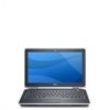
USB 2.0 connector 8. optical drive 11. ExpressCard slot 12. eSata/USB connector 7. volume control buttons 9. fingerprint reader Regulatory Model: P12S Regulatory Type: P12S001 February 2011 Front and Back View Figure 1. microphone 2. display 5. Front view 1. Dell Latitude E6320 Setup and Features Information About Warnings WARNING: A WARNING indicates a potential for property damage, personal injury, or death. wireless switch 10. camera 3. power button 6. camera status light 4.
USB 2.0 connector 8. optical drive 11. ExpressCard slot 12. eSata/USB connector 7. volume control buttons 9. fingerprint reader Regulatory Model: P12S Regulatory Type: P12S001 February 2011 Front and Back View Figure 1. microphone 2. display 5. Front view 1. Dell Latitude E6320 Setup and Features Information About Warnings WARNING: A WARNING indicates a potential for property damage, personal injury, or death. wireless switch 10. camera 3. power button 6. camera status light 4.
User Manual
Page 2
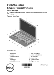
.... keyboard 20. network connector 2. security cable slot 5. power connector 6. smart card slot WARNING: Do not block, push objects into, or allow dust to accumulate in a low-airflow environment, such as a closed briefcase, while it is normal and does not indicate a problem with your Dell computer in the air vents. The computer turns on the fan when the computer gets hot. device status lights Figure 2. power and battery...
.... keyboard 20. network connector 2. security cable slot 5. power connector 6. smart card slot WARNING: Do not block, push objects into, or allow dust to accumulate in a low-airflow environment, such as a closed briefcase, while it is normal and does not indicate a problem with your Dell computer in the air vents. The computer turns on the fan when the computer gets hot. device status lights Figure 2. power and battery...
Owners Manual
Page 5
... Bluetooth Card 47 Removing The Bluetooth Card 47 Installing The Bluetooth Card 48 17 LED Board 49 Removing The LED Board 49 Installing The LED Board 51 18 Smart Card Reader 53 Removing The Smart Card Reader 53 Installing The Smart Card Reader 55 19 Media Board 57 Removing The Media Board 57 Installing The Media Board 59 20 Display Hinges 61 Removing The Display Hinge Covers 61 Installing The Display Hinge Covers 62 21 Display Assembly 63 Removing The Display Assembly 63 Installing The Display Assembly 67 22 System Board 69 Removing The System Board 69 Installing...
... Bluetooth Card 47 Removing The Bluetooth Card 47 Installing The Bluetooth Card 48 17 LED Board 49 Removing The LED Board 49 Installing The LED Board 51 18 Smart Card Reader 53 Removing The Smart Card Reader 53 Installing The Smart Card Reader 55 19 Media Board 57 Removing The Media Board 57 Installing The Media Board 59 20 Display Hinges 61 Removing The Display Hinge Covers 61 Installing The Display Hinge Covers 62 21 Display Assembly 63 Removing The Display Assembly 63 Installing The Display Assembly 67 22 System Board 69 Removing The System Board 69 Installing...
Owners Manual
Page 6
... Port 87 Removing The DC-In Port 87 Installing The DC-In Port 89 27 Display Bezel 91 Removing The Display Bezel 91 Installing The Display Bezel 92 28 Display Panel 93 Removing The Display Panel 93 Installing The Display Panel 94 29 Camera...95 Removing The Camera...95 Installing The Camera...96 30 Specifications 97 Technical Specifications 97 31 System Setup 103 Overview...103 Entering System Setup 103 System Setup Menu Options 103 32 Diagnostics 115 Device Status Lights...115 Battery Status Lights...115 LED Error Codes...
... Port 87 Removing The DC-In Port 87 Installing The DC-In Port 89 27 Display Bezel 91 Removing The Display Bezel 91 Installing The Display Bezel 92 28 Display Panel 93 Removing The Display Panel 93 Installing The Display Panel 94 29 Camera...95 Removing The Camera...95 Installing The Camera...96 30 Specifications 97 Technical Specifications 97 31 System Setup 103 Overview...103 Entering System Setup 103 System Setup Menu Options 103 32 Diagnostics 115 Device Status Lights...115 Battery Status Lights...115 LED Error Codes...
Owners Manual
Page 9
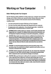
.... • A component can be done by periodically touching an unpainted metal surface, such as a connector on the back of cable, press in on the locking tabs before you connect a cable, ensure that is not authorized by Dell is not covered by performing the removal procedure in reverse order. Damage due to servicing that both connectors are disconnecting this document assumes...
.... • A component can be done by periodically touching an unpainted metal surface, such as a connector on the back of cable, press in on the locking tabs before you connect a cable, ensure that is not authorized by Dell is not covered by performing the removal procedure in reverse order. Damage due to servicing that both connectors are disconnecting this document assumes...
Owners Manual
Page 10
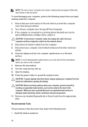
...-side up. 9. CAUTION: Before touching anything inside the computer. 1. Press the power button to dissipate static electricity, which could harm internal components. 11. Turn off your computer and all network cables from the appropriate slots. Close the display and turn the computer upside-down on a flat work surface is connected to prevent the computer cover from being scratched. 2. Open the display. 10. If the computer...
...-side up. 9. CAUTION: Before touching anything inside the computer. 1. Press the power button to dissipate static electricity, which could harm internal components. 11. Turn off your computer and all network cables from the appropriate slots. Close the display and turn the computer upside-down on a flat work surface is connected to prevent the computer cover from being scratched. 2. Open the display. 10. If the computer...
Owners Manual
Page 11
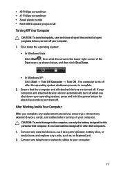
... the operating system shutdown process is complete. 2. The computer turns off . Connect any external devices, such as a port replicator, battery slice, or media base, and replace any cards, such as shown below, and then click Shut Down. • In Windows XP: Click Start → Turn Off Computer → Turn Off . • #0 Phillips screwdriver • #1 Phillips screwdriver • Small plastic scribe • Flash BIOS update program CD Turning Off...
... the operating system shutdown process is complete. 2. The computer turns off . Connect any external devices, such as a port replicator, battery slice, or media base, and replace any cards, such as shown below, and then click Shut Down. • In Windows XP: Click Start → Turn Off Computer → Turn Off . • #0 Phillips screwdriver • #1 Phillips screwdriver • Small plastic scribe • Flash BIOS update program CD Turning Off...
Owners Manual
Page 22
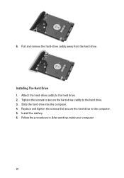
Pull and remove the hard-drive caddy away from the hard drive. Slide the hard drive into the computer. 4. Replace and tighten the screws that secure the hard drive to the hard drive. 3. Install the battery. 6. Tighten the screws to secure the hard-drive caddy to the computer. 5. Installing The Hard Drive 1. Follow the procedures in After working inside your computer. 22 6. Attach the hard-drive caddy to the hard drive. 2.
Pull and remove the hard-drive caddy away from the hard drive. Slide the hard drive into the computer. 4. Replace and tighten the screws that secure the hard drive to the hard drive. 3. Install the battery. 6. Tighten the screws to secure the hard-drive caddy to the computer. 5. Installing The Hard Drive 1. Follow the procedures in After working inside your computer. 22 6. Attach the hard-drive caddy to the hard drive. 2.
Owners Manual
Page 43
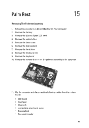
...) card. 4. Remove the base cover. 6. Flip the computer and disconnect the following cables from the system board: • LED board • touchpad • bluetooth • contactless smart card reader • ExpressCard • fingerprint reader 43 Remove the keyboard. 10. Remove the keyboard trim. 9. Remove the ExpressCard. 7. Remove the optical drive. 5. Remove the screws that secure the palmrest assembly to the computer. 11. Remove the battery. 3. Palm Rest 15 Removing The Palmrest Assembly 1. Remove the hard drive...
...) card. 4. Remove the base cover. 6. Flip the computer and disconnect the following cables from the system board: • LED board • touchpad • bluetooth • contactless smart card reader • ExpressCard • fingerprint reader 43 Remove the keyboard. 10. Remove the keyboard trim. 9. Remove the ExpressCard. 7. Remove the optical drive. 5. Remove the screws that secure the palmrest assembly to the computer. 11. Remove the battery. 3. Palm Rest 15 Removing The Palmrest Assembly 1. Remove the hard drive...
Owners Manual
Page 45
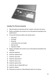
Connect the following cables to the computer. 5. Install the ExpressCard. 9. Install the optical drive. 11. Installing The Palmrest Assembly 1. Install the hard drive. 8. Install the Secure Digital (SD) card. 12. Replace and tighten the screws to secure the palmrest assembly to the system board: • LED board • touchpad • bluetooth • contactless smart card reader • Express Card • fingerprint reader 4. Install the keyboard trim. 7. Install the battery. 13. Align the palmrest assembly with the...
Connect the following cables to the computer. 5. Install the ExpressCard. 9. Install the optical drive. 11. Installing The Palmrest Assembly 1. Install the hard drive. 8. Install the Secure Digital (SD) card. 12. Replace and tighten the screws to secure the palmrest assembly to the system board: • LED board • touchpad • bluetooth • contactless smart card reader • Express Card • fingerprint reader 4. Install the keyboard trim. 7. Install the battery. 13. Align the palmrest assembly with the...
Owners Manual
Page 97
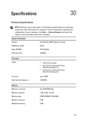
For more information regarding the configuration of your computer, click Start → Help and Support and select the option to 6 MB 1333 MHz Memory Memory connector Memory capacity Memory type Minimum memory Maximum memory two SODIMM slots 1 GB, 2 GB, or 4 GB DDR3 SDRAM (1333 MHz) 2 GB 8 GB 97 Specifications 30 Technical Specifications NOTE: Offerings may vary by law to ship with Turbo BoostTechnology 2.0 up to...
For more information regarding the configuration of your computer, click Start → Help and Support and select the option to 6 MB 1333 MHz Memory Memory connector Memory capacity Memory type Minimum memory Maximum memory two SODIMM slots 1 GB, 2 GB, or 4 GB DDR3 SDRAM (1333 MHz) 2 GB 8 GB 97 Specifications 30 Technical Specifications NOTE: Offerings may vary by law to ship with Turbo BoostTechnology 2.0 up to...
Owners Manual
Page 98
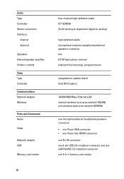
Audio Type Controller Stereo conversion Interface: Internal External Speakers Internal speaker amplifier Volume controls Video Type Controller Communications Network adapter Wireless Ports and Connectors Audio Video Network adapter USB Memory card reader 98 four-channel high definition audio IDT 92HD90 24-bit (analog-to-digital and digital-to-analog) high definition audio microphone-in/stereo headphones/external speakers connector two 0.5 W (typical) per channel keyboard function keys, program menus integrated on system board Intel HD Graphics 10/100/1000 Mbps Ethernet LAN internal wireless ...
Audio Type Controller Stereo conversion Interface: Internal External Speakers Internal speaker amplifier Volume controls Video Type Controller Communications Network adapter Wireless Ports and Connectors Audio Video Network adapter USB Memory card reader 98 four-channel high definition audio IDT 92HD90 24-bit (analog-to-digital and digital-to-analog) high definition audio microphone-in/stereo headphones/external speakers connector two 0.5 W (typical) per channel keyboard function keys, program menus integrated on system board Intel HD Graphics 10/100/1000 Mbps Ethernet LAN internal wireless ...
Owners Manual
Page 103
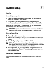
... user password. • read the current amount of memory or set the type of hard drive installed. System Setup Menu Options The following sections describe the menu options available in your computer to display, and then press . Then, shut down the System Setup screen information for the F2 prompt to appear. 3. System Setup 31 Overview System Setup allows you to: • change the system configuration information after you add, change, or remove...
... user password. • read the current amount of memory or set the type of hard drive installed. System Setup Menu Options The following sections describe the menu options available in your computer to display, and then press . Then, shut down the System Setup screen information for the F2 prompt to appear. 3. System Setup 31 Overview System Setup allows you to: • change the system configuration information after you add, change, or remove...
Owners Manual
Page 104
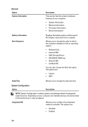
... to configure the integrated network controller. The options are : • Disabled • Enabled 104 Depending on your computer. • System Information • Memory Information • Processor Information • Device Information Battery Information Boot Sequence Displays the battery status and the type of your computer and installed devices, the items listed in which the computer attempts to find an operating system. • Diskette Drive • Internal HDD • USB Storage Device • CD/DVD...
... to configure the integrated network controller. The options are : • Disabled • Enabled 104 Depending on your computer. • System Information • Memory Information • Processor Information • Device Information Battery Information Boot Sequence Displays the battery status and the type of your computer and installed devices, the items listed in which the computer attempts to find an operating system. • Diskette Drive • Internal HDD • USB Storage Device • CD/DVD...
Owners Manual
Page 106
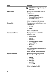
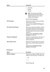
... Dev • Disable USB Controller Default Setting: Enable USB Controller Allows you to support RAID mode. The options are : • Disabled • Level is 25% • Level is 50% • Level is 50% • Levels is 100% Default Setting: Level is configured to enable or disable the following devices: • Internal Modem • Fixed Bay • eSATA Ports • Hard Drive Free Fall Protection • External USB Port • Microphone • Camera You can also enable or disable Media Card and 1394 together...
... Dev • Disable USB Controller Default Setting: Enable USB Controller Allows you to support RAID mode. The options are : • Disabled • Level is 25% • Level is 50% • Level is 50% • Levels is 100% Default Setting: Level is configured to enable or disable the following devices: • Internal Modem • Fixed Bay • eSATA Ports • Hard Drive Free Fall Protection • External USB Port • Microphone • Camera You can also enable or disable Media Card and 1394 together...
Owners Manual
Page 108
... to enforce the option to bypass the System and the Internal HDD password, when they are : • Disabled • Reboot bypass Default Setting: Disabled Allows you to enable or disable the permission to always set . Default Setting: The option is not selected. Allows you to enable the disable permission to enter the Option ROM Configuration screens using hotkeys during POST. Default Setting: Enable Stron Password is disabled. NOTE: Successful password changes take effect immediately. The options are set . Default Setting: Allow Non-Admin Password Changes is set .
... to enforce the option to bypass the System and the Internal HDD password, when they are : • Disabled • Reboot bypass Default Setting: Disabled Allows you to enable or disable the permission to always set . Default Setting: The option is not selected. Allows you to enable the disable permission to enter the Option ROM Configuration screens using hotkeys during POST. Default Setting: Enable Stron Password is disabled. NOTE: Successful password changes take effect immediately. The options are set . Default Setting: Allow Non-Admin Password Changes is set .
Owners Manual
Page 109
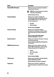
...The options are locked by the admin password. If disabled the setup options are : • All •1 •2 Default Setting: All 109 Allows you to prevent users from entering Setup when an Administrator password is not selected. Default Setting: Allow Wireless Switch Changesis not selected. Description Allows you to enable the Execute Disable mode of Administrator and System passwords. Default Setting: Enable Admin Setup Lockout is set . Default Setting: Enable CPU XD Support is set . Option CPU XD Support Non-Admin Setup Changes Password Configuration Admin Setup Lockout...
...The options are locked by the admin password. If disabled the setup options are : • All •1 •2 Default Setting: All 109 Allows you to prevent users from entering Setup when an Administrator password is not selected. Default Setting: Allow Wireless Switch Changesis not selected. Description Allows you to enable the Execute Disable mode of Administrator and System passwords. Default Setting: Enable Admin Setup Lockout is set . Default Setting: Enable CPU XD Support is set . Option CPU XD Support Non-Admin Setup Changes Password Configuration Admin Setup Lockout...
Owners Manual
Page 111
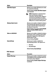
... switches from wired or wireless networks without depending on the computer from the Off state when triggered by a LAN signal or WLAN signal or both. If the AC power adapter is connected. The options are selected. NOTE: This feature is only functional when the AC power adapter is removed during Standby, the system setup will remove power from all of the USB ports to enable or disable the system setup (BIOS...
... switches from wired or wireless networks without depending on the computer from the Off state when triggered by a LAN signal or WLAN signal or both. If the AC power adapter is connected. The options are selected. NOTE: This feature is only functional when the AC power adapter is removed during Standby, the system setup will remove power from all of the USB ports to enable or disable the system setup (BIOS...
Owners Manual
Page 112
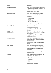
... mouse and touch pad input. Allows you to enable the keypad that is used to speed up the boot process. Default Setting: Fn Key Only Allows you enable the sign-on screen message display indicating the keystroke sequence to enable the Numlock option when the computer boots. Default Setting: Enable Legacy USB Emulation is selected. Allows to set the option where the key is embedded in the internal keyboard. Allows you to access the System Setup option menu. The options...
... mouse and touch pad input. Allows you to enable the keypad that is used to speed up the boot process. Default Setting: Fn Key Only Allows you enable the sign-on screen message display indicating the keystroke sequence to enable the Numlock option when the computer boots. Default Setting: Enable Legacy USB Emulation is selected. Allows to set the option where the key is embedded in the internal keyboard. Allows you to access the System Setup option menu. The options...
Owners Manual
Page 115
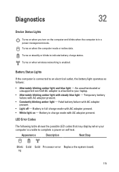
... non-Dell AC adapter is unable to indicate battery charge status. Appearance Description Next Step Blinki Solid Solid Processor error Replace the system board. Fatal battery failure with AC adapter present. • Constantly blinking amber light - Battery in full charge mode with AC adapter present. Turns on when wireless networking is in a power management mode. Battery in charge mode with AC adapter present. • White light on the computer and blinks when the computer is enabled. Diagnostics 32 Device Status Lights Turns...
... non-Dell AC adapter is unable to indicate battery charge status. Appearance Description Next Step Blinki Solid Solid Processor error Replace the system board. Fatal battery failure with AC adapter present. • Constantly blinking amber light - Battery in full charge mode with AC adapter present. Turns on when wireless networking is in a power management mode. Battery in charge mode with AC adapter present. • White light on the computer and blinks when the computer is enabled. Diagnostics 32 Device Status Lights Turns...


