Service Manual
Page 6
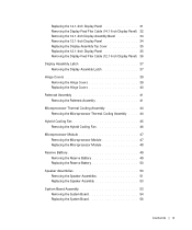
... Removing the Display-Feed Flex Cable (12.1-Inch Display Panel) 36 Display Assembly Latch 37 Removing the Display Assembly Latch 37 Hinge Covers 39 Removing the Hinge Covers 39 Replacing the Hinge Covers 40 Palmrest Assembly 41 Removing the Palmrest Assembly 41 Microprocessor Thermal Cooling Assembly 44 Removing the Microprocessor Thermal Cooling Assembly...
... Removing the Display-Feed Flex Cable (12.1-Inch Display Panel) 36 Display Assembly Latch 37 Removing the Display Assembly Latch 37 Hinge Covers 39 Removing the Hinge Covers 39 Replacing the Hinge Covers 40 Palmrest Assembly 41 Removing the Palmrest Assembly 41 Microprocessor Thermal Cooling Assembly 44 Removing the Microprocessor Thermal Cooling Assembly...
Service Manual
Page 13
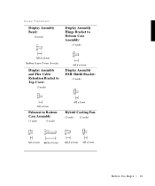
Screw Placement Display Assembly Bezel: (6 each) Display Assembly Hinge Bracket to Bottom Case Assembly: (5 each) Rubber Screw Covers (6 each) Display Assembly and Flex Cable Retention Bracket to Top Cover: (5 each) Display Assembly EMI Shield Bracket: (2 each) Palmrest to Bottom Case Assembly: (5 each) (3 each) Hybrid Cooling Fan: (2 each) (1 each) B e fo re You Be gin 13
Screw Placement Display Assembly Bezel: (6 each) Display Assembly Hinge Bracket to Bottom Case Assembly: (5 each) Rubber Screw Covers (6 each) Display Assembly and Flex Cable Retention Bracket to Top Cover: (5 each) Display Assembly EMI Shield Bracket: (2 each) Palmrest to Bottom Case Assembly: (5 each) (3 each) Hybrid Cooling Fan: (2 each) (1 each) B e fo re You Be gin 13
Service Manual
Page 15
SECTION 2 Removing and Replacing Parts Components Hard Drive Memory Module Mini-PCI Card Assembly Keyboard Assembly Removing the Display Assembly Display Assembly Latch Hinge Covers Palmrest Assembly Microprocessor Thermal Cooling Assembly Hybrid Cooling Fan Microprocessor Module Reserve Battery Speaker Assemblies System Board Assembly Battery and Modular Bay Latch Assemblies www.dell.com | support.dell.com
SECTION 2 Removing and Replacing Parts Components Hard Drive Memory Module Mini-PCI Card Assembly Keyboard Assembly Removing the Display Assembly Display Assembly Latch Hinge Covers Palmrest Assembly Microprocessor Thermal Cooling Assembly Hybrid Cooling Fan Microprocessor Module Reserve Battery Speaker Assemblies System Board Assembly Battery and Modular Bay Latch Assemblies www.dell.com | support.dell.com
Service Manual
Page 26
NOTICE: Disconnect the computer and any attached devices from electrical outlets, and remove any installed batteries. www.dell.com | support.dell.com NOTICE: Position the keyboard flex cable so it is correctly installed. the display assembly hinges pass through the back of the palmrest. 5 Reinstall the five M2.5 x 12-mm screws in the bottom...
NOTICE: Disconnect the computer and any attached devices from electrical outlets, and remove any installed batteries. www.dell.com | support.dell.com NOTICE: Position the keyboard flex cable so it is correctly installed. the display assembly hinges pass through the back of the palmrest. 5 Reinstall the five M2.5 x 12-mm screws in the bottom...
Service Manual
Page 28
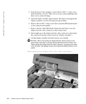
...-feed flex cable connector to disconnect the connector from the system board (see "Reconnecting the Display-Feed Flex Cable Connector"). Pressing on the top left hinge. 5 Open the display assembly approximately 180 degrees and support the display assembly so it does not open past this position. 6 Remove the two M2...protection in the system. Reconnecting the Display-Feed Flex Cable Connector 28 Removi ng and Replacing Parts There are two screws on the right hinge and three screws on the left and right ends of the computer, remove the five M2.5 x 5-mm screws labeled with the "circle D."...
...-feed flex cable connector to disconnect the connector from the system board (see "Reconnecting the Display-Feed Flex Cable Connector"). Pressing on the top left hinge. 5 Open the display assembly approximately 180 degrees and support the display assembly so it does not open past this position. 6 Remove the two M2...protection in the system. Reconnecting the Display-Feed Flex Cable Connector 28 Removi ng and Replacing Parts There are two screws on the right hinge and three screws on the left and right ends of the computer, remove the five M2.5 x 5-mm screws labeled with the "circle D."...
Service Manual
Page 30
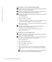
...Remove the display assembly. 3 Use the scribe to carefully separate the bezel from electrical outlets, and remove any installed batteries. www.dell.com | support.dell.com Removing the 14.1-Inch Display Assembly Bezel NOTICE: Disconnect the computer and any attached devices from the display-assembly top cover. ... unpainted metal surface on the computer. 1 Remove the hard drive. 2 Remove the display assembly. 3 Remove the display assembly bezel. 4 Remove the hinge covers. 5 Remove the two M2 x 4-mm screws on the left side of the display panel. NOTE: If you have a Hitachi display panel,...
...Remove the display assembly. 3 Use the scribe to carefully separate the bezel from electrical outlets, and remove any installed batteries. www.dell.com | support.dell.com Removing the 14.1-Inch Display Assembly Bezel NOTICE: Disconnect the computer and any attached devices from the display-assembly top cover. ... unpainted metal surface on the computer. 1 Remove the hard drive. 2 Remove the display assembly. 3 Remove the display assembly bezel. 4 Remove the hinge covers. 5 Remove the two M2 x 4-mm screws on the left side of the display panel. NOTE: If you have a Hitachi display panel,...
Service Manual
Page 34
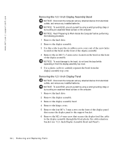
....1-Inch Display Panel NOTICE: Disconnect the computer and any attached devices from electrical outlets, and remove any installed batteries. www.dell.com | support.dell.com Removing the 12.1-Inch Display Assembly Bezel NOTICE: Disconnect the computer and any attached devices from electrical outlets, and remove...unpainted metal surface on the computer. 1 Remove the hard drive. 2 Remove the display assembly. 3 Remove the display assembly bezel. 4 Remove the hinge covers. 5 Remove the four M3 x 3-mm screws on the front of the display panel that secure the display panel to the support bracket....
....1-Inch Display Panel NOTICE: Disconnect the computer and any attached devices from electrical outlets, and remove any installed batteries. www.dell.com | support.dell.com Removing the 12.1-Inch Display Assembly Bezel NOTICE: Disconnect the computer and any attached devices from electrical outlets, and remove...unpainted metal surface on the computer. 1 Remove the hard drive. 2 Remove the display assembly. 3 Remove the display assembly bezel. 4 Remove the hinge covers. 5 Remove the four M3 x 3-mm screws on the front of the display panel that secure the display panel to the support bracket....
Service Manual
Page 39
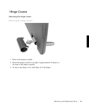
Hinge Covers Removing the Hinge Covers Removing the Hinge Covers 1 Remove the display assembly. 2 Rotate the hinges forward at an angle of approximately 90 degrees to the front of the display assembly. 3 To remove the hinge covers, slide them off of the hinges. Removing and Repl aci ng Part s 39
Hinge Covers Removing the Hinge Covers Removing the Hinge Covers 1 Remove the display assembly. 2 Rotate the hinges forward at an angle of approximately 90 degrees to the front of the display assembly. 3 To remove the hinge covers, slide them off of the hinges. Removing and Repl aci ng Part s 39
Service Manual
Page 40
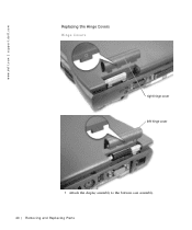
www.dell.com | support.dell.com Replacing the Hinge Covers Hinge Covers right rhiginhgtehcinogveercover left hinge cover 1 Attach the display assembly to the bottom case assembly. 40 Removi ng and Replacing Parts
www.dell.com | support.dell.com Replacing the Hinge Covers Hinge Covers right rhiginhgtehcinogveercover left hinge cover 1 Attach the display assembly to the bottom case assembly. 40 Removi ng and Replacing Parts
Service Manual
Page 41
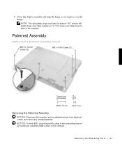
...by using a wrist grounding strap or by touching an unpainted metal surface on the computer. 2 Close the display assembly and snap the hinge covers in place over the hinges. Palmrest Assembly Removing the Palmrest Assembly Screws M2.5 x 12-mm screws (3) M2 x 3-mm screws (2) Removing the Palmrest Assembly NOTICE:... Disconnect the computer and any attached devices from electrical outlets, and remove any installed batteries. The hinge cover labels face the back of the computer. Removing and Repl aci ng Part s 41 NOTE: The right plastic...
...by using a wrist grounding strap or by touching an unpainted metal surface on the computer. 2 Close the display assembly and snap the hinge covers in place over the hinges. Palmrest Assembly Removing the Palmrest Assembly Screws M2.5 x 12-mm screws (3) M2 x 3-mm screws (2) Removing the Palmrest Assembly NOTICE:... Disconnect the computer and any attached devices from electrical outlets, and remove any installed batteries. The hinge cover labels face the back of the computer. Removing and Repl aci ng Part s 41 NOTE: The right plastic...
Service Manual
Page 42
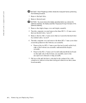
...1 Remove the hard drive. 2 Remove the keyboard. www.dell.com | support.dell.com NOTICE: Read "Preparing to remove it from the touch pad connector on the system board assembly. 42 Removi ng and Replacing Parts the display assembly hinges pass through the back of the palmrest assembly. 3 Remove the... display hinge cover and display assembly. 4 Turn the ...
...1 Remove the hard drive. 2 Remove the keyboard. www.dell.com | support.dell.com NOTICE: Read "Preparing to remove it from the touch pad connector on the system board assembly. 42 Removi ng and Replacing Parts the display assembly hinges pass through the back of the palmrest assembly. 3 Remove the... display hinge cover and display assembly. 4 Turn the ...
Service Manual
Page 59
... display panel (14.1-inch) removing, 30 replacing, 31 display-assembly top cover replacing, 35 display-feed flex cable H hard drive, 17 removing, 17 replacing, 17 hinge covers removing, 39 replacing, 40 hybrid cooling fan removing, 46 K keyboard, 23 removing, 23 replacing, 25 M memory module, 18 removing, 19 replacing, 20 microprocessor module...
... display panel (14.1-inch) removing, 30 replacing, 31 display-assembly top cover replacing, 35 display-feed flex cable H hard drive, 17 removing, 17 replacing, 17 hinge covers removing, 39 replacing, 40 hybrid cooling fan removing, 46 K keyboard, 23 removing, 23 replacing, 25 M memory module, 18 removing, 19 replacing, 20 microprocessor module...


