Service Manual
Page 10
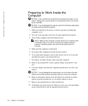
... from the PC Card slot. 9 Close the display and turn the computer upside down the computer using the computer's operating system, press and hold the power button for 4 seconds. 4 Make sure the computer is undocked. 5 Disconnect the computer from the electrical outlet. 6 To avoid possible damage to the ...other external cables from the computer. 8 Remove any installed PC Cards or plastic blanks from the modular bay, if a secondary battery is not covered by Dell is in use a wrist grounding strap or periodically touch an unpainted metal surface. 10 Be fo r e Yo u Be g in Damage due to ...
... from the PC Card slot. 9 Close the display and turn the computer upside down the computer using the computer's operating system, press and hold the power button for 4 seconds. 4 Make sure the computer is undocked. 5 Disconnect the computer from the electrical outlet. 6 To avoid possible damage to the ...other external cables from the computer. 8 Remove any installed PC Cards or plastic blanks from the modular bay, if a secondary battery is not covered by Dell is in use a wrist grounding strap or periodically touch an unpainted metal surface. 10 Be fo r e Yo u Be g in Damage due to ...
Service Manual
Page 46
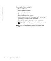
... when reinserting the fan cable. 46 Removi ng and Replacing Parts NOTE: The fan power cable is long, and can be pulled out from the system board interface connector and remove the hybrid cooling fan. www.dell.com | support.dell.com Removing the Hybrid Cooling Fan 1 Remove the hard drive. 2 Remove the keyboard... assembly. 6 Remove the two M2.5 x 5-mm screws and one M2 x 3-mm screw that secure the hybrid cooling fan to the system board. 7 Disconnect the fan power cable from under the EMI shield to provide access to the connector.
... when reinserting the fan cable. 46 Removi ng and Replacing Parts NOTE: The fan power cable is long, and can be pulled out from the system board interface connector and remove the hybrid cooling fan. www.dell.com | support.dell.com Removing the Hybrid Cooling Fan 1 Remove the hard drive. 2 Remove the keyboard... assembly. 6 Remove the two M2.5 x 5-mm screws and one M2 x 3-mm screw that secure the hybrid cooling fan to the system board. 7 Disconnect the fan power cable from under the EMI shield to provide access to the connector.
Service Manual
Page 49
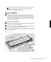
... using a wrist grounding strap or by touching an unpainted metal surface on the computer. Reserve Battery NOTICE: The reserve battery provides power to update or flash the BIOS, see the Dell Portable Computer BIOS Update Guide. If possible, make a copy of this information before performing the following procedure. NOTICE: Read "Preparing to...
... using a wrist grounding strap or by touching an unpainted metal surface on the computer. Reserve Battery NOTICE: The reserve battery provides power to update or flash the BIOS, see the Dell Portable Computer BIOS Update Guide. If possible, make a copy of this information before performing the following procedure. NOTICE: Read "Preparing to...
System Information Guide
Page 5
... that the total ampere rating of the products plugged into the extension cable does not exceed the ampere rating of the extension cable. 1-2 Dell Latitude System Information With extended operation, heat can cause fire or electric shock by shorting out interior components. • Use only the... or swimming pool or in the base. Doing so can potentially build up in a wet basement. • Do not push objects into properly grounded power sources. Do not cover the AC adapter with threeprong plugs to charge the battery. If you must use an extension cable, use a three-wire cable...
... that the total ampere rating of the products plugged into the extension cable does not exceed the ampere rating of the extension cable. 1-2 Dell Latitude System Information With extended operation, heat can cause fire or electric shock by shorting out interior components. • Use only the... or swimming pool or in the base. Doing so can potentially build up in a wet basement. • Do not push objects into properly grounded power sources. Do not cover the AC adapter with threeprong plugs to charge the battery. If you must use an extension cable, use a three-wire cable...
System Information Guide
Page 6
... access the inside your computer. NOTICE: The only time you should be manufactured with household waste. support.dell.com Dell Latitude System Information 1-3 (Rev. 11/3/98) FILE LOCATION: D:\Eri_DProject\Dell\Temp\413CU0s\413CUeb0.fm • To remove power from the computer, turn it . • Disconnect any peripherals attached to your computer, including telephone or telecommunication...
... access the inside your computer. NOTICE: The only time you should be manufactured with household waste. support.dell.com Dell Latitude System Information 1-3 (Rev. 11/3/98) FILE LOCATION: D:\Eri_DProject\Dell\Temp\413CU0s\413CUeb0.fm • To remove power from the computer, turn it . • Disconnect any peripherals attached to your computer, including telephone or telecommunication...
System Information Guide
Page 7
... on the World Wide Web at http:// www.dell.com. • Protecting against Electrostatic Discharge: Static electricity can do so by Dell could void your online User's Guide. 1-4 Dell Latitude System Information (Rev. 11/3/98) FILE LOCATION: D:\Eri_DProject\Dell\Temp\413CU0s\413CUeb0.fm General EMC Guidelines •..., a cable is designed to operate the equipment. If you prefer, you can be found in free space or conducted along power or signal leads, that you touch any signal or emission, radiated in your authority to comply with applicable regulations regarding your computer...
... on the World Wide Web at http:// www.dell.com. • Protecting against Electrostatic Discharge: Static electricity can do so by Dell could void your online User's Guide. 1-4 Dell Latitude System Information (Rev. 11/3/98) FILE LOCATION: D:\Eri_DProject\Dell\Temp\413CU0s\413CUeb0.fm General EMC Guidelines •..., a cable is designed to operate the equipment. If you prefer, you can be found in free space or conducted along power or signal leads, that you touch any signal or emission, radiated in your authority to comply with applicable regulations regarding your computer...
System Information Guide
Page 8
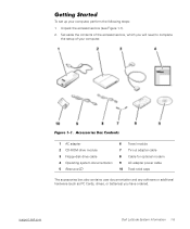
... adapter power cable 10 Track stick caps The accessories box also contains user documentation and any software or additional hardware (such as PC Cards, drives, or batteries) you will need to complete the setup of the accessories box, which you have ordered. support.dell.com Dell Latitude System... Information 1-5 (Rev. 11/3/98) FILE LOCATION: D:\Eri_DProject\Dell\Temp\413CU0s\413CUeb0.fm Getting Started To set up your computer. Set aside the contents of your ...
... adapter power cable 10 Track stick caps The accessories box also contains user documentation and any software or additional hardware (such as PC Cards, drives, or batteries) you will need to complete the setup of the accessories box, which you have ordered. support.dell.com Dell Latitude System... Information 1-5 (Rev. 11/3/98) FILE LOCATION: D:\Eri_DProject\Dell\Temp\413CU0s\413CUeb0.fm Getting Started To set up your computer. Set aside the contents of your ...
System Information Guide
Page 9
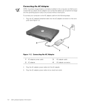
...is already installed in the computer, but Dell recommends that you attach the AC adapter now so that the battery can complete its charge and the operating system setup can proceed without interruption. Connecting the AC Adapter 1 AC adapter power cable 2 AC adapter 3 AC adapter ...into the AC adapter. 3. Plug the AC adapter power cable into the AC adapter connector on the computer (see Figure 1-2). To connect your computer to the AC adapter, perform the following steps: 1. Plug the AC adapter power cable into an electrical outlet. 1-6 Dell Latitude System Information Figure 1-2.
...is already installed in the computer, but Dell recommends that you attach the AC adapter now so that the battery can complete its charge and the operating system setup can proceed without interruption. Connecting the AC Adapter 1 AC adapter power cable 2 AC adapter 3 AC adapter ...into the AC adapter. 3. Plug the AC adapter power cable into the AC adapter connector on the computer (see Figure 1-2). To connect your computer to the AC adapter, perform the following steps: 1. Plug the AC adapter power cable into an electrical outlet. 1-6 Dell Latitude System Information Figure 1-2.
System Information Guide
Page 10
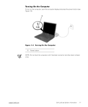
Figure 1-3. Turning On the Computer 1 Power button NOTE: Do not dock the computer until it has been turned on the computer, open the computer display and press the power button (see Figure 1-3). (Rev. 11/3/98) FILE LOCATION: D:\Eri_DProject\Dell\Temp\413CU0s\413CUeb0.fm Turning On the Computer To turn on and shut down at least once. support.dell.com Dell Latitude System Information 1-7
Figure 1-3. Turning On the Computer 1 Power button NOTE: Do not dock the computer until it has been turned on the computer, open the computer display and press the power button (see Figure 1-3). (Rev. 11/3/98) FILE LOCATION: D:\Eri_DProject\Dell\Temp\413CU0s\413CUeb0.fm Turning On the Computer To turn on and shut down at least once. support.dell.com Dell Latitude System Information 1-7
System Information Guide
Page 11
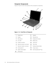
Front View of the computer's components. Figure 1-4. (Rev. 11/3/98) FILE LOCATION: D:\Eri_DProject\Dell\Temp\413CU0s\413CUeb0.fm Computer Components Figures 1-4 and 1-5 show the locations of Computer 1 Display latch 11 Speaker 2 Display 12 Modular bay 3 Microphone 13 Display latch...outlet 14 Battery bay 5 S-Video connector 15 Touch pad 6 Optional network connector 16 Track stick 7 Optional modem connector 17 Keyboard status lights 8 Audio jacks (2) 18 Power button 9 System status lights 19 Dell AccessDirect™ key 10 Infrared port 1-8 Dell Latitude System Information
Front View of the computer's components. Figure 1-4. (Rev. 11/3/98) FILE LOCATION: D:\Eri_DProject\Dell\Temp\413CU0s\413CUeb0.fm Computer Components Figures 1-4 and 1-5 show the locations of Computer 1 Display latch 11 Speaker 2 Display 12 Modular bay 3 Microphone 13 Display latch...outlet 14 Battery bay 5 S-Video connector 15 Touch pad 6 Optional network connector 16 Track stick 7 Optional modem connector 17 Keyboard status lights 8 Audio jacks (2) 18 Power button 9 System status lights 19 Dell AccessDirect™ key 10 Infrared port 1-8 Dell Latitude System Information
System Information Guide
Page 14
... with the computer in one hand while pulling the battery out of these ways. c. support.dell.com Dell Latitude System Information 1-11 After 4 minutes, the computer shuts down and you have up to 4 minutes to step 5. 4. When the green power indicator turns off, continue. • For Windows 2000, use suspend or standby mode. Close...
... with the computer in one hand while pulling the battery out of these ways. c. support.dell.com Dell Latitude System Information 1-11 After 4 minutes, the computer shuts down and you have up to 4 minutes to step 5. 4. When the green power indicator turns off, continue. • For Windows 2000, use suspend or standby mode. Close...
System Information Guide
Page 15
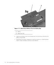
You should hear a click when the battery is in, press the power button or open the display to resume normal operation. 1-12 Dell Latitude System Information Depending on the power management mode the computer is fully seated. 7. Slide the new battery firmly into the battery bay. Removing a Battery From the Battery Bay 1 Battery 2 Battery bay latch 6. (Rev. 11/3/98) FILE LOCATION: D:\Eri_DProject\Dell\Temp\413CU0s\413CUeb0.fm Figure 1-7.
You should hear a click when the battery is in, press the power button or open the display to resume normal operation. 1-12 Dell Latitude System Information Depending on the power management mode the computer is fully seated. 7. Slide the new battery firmly into the battery bay. Removing a Battery From the Battery Bay 1 Battery 2 Battery bay latch 6. (Rev. 11/3/98) FILE LOCATION: D:\Eri_DProject\Dell\Temp\413CU0s\413CUeb0.fm Figure 1-7.


