Service Manual
Page 6
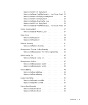
... Palmrest Assembly 41 Removing the Palmrest Assembly 41 Microprocessor Thermal Cooling Assembly 44 Removing the Microprocessor Thermal Cooling Assembly . . . . 44 Hybrid Cooling Fan 45 Removing the Hybrid Cooling Fan 46 Microprocessor Module 47 Removing the Microprocessor Module 47 Replacing the Microprocessor Module 48 Reserve Battery 49 Removing the Reserve Battery 49 Replacing...
... Palmrest Assembly 41 Removing the Palmrest Assembly 41 Microprocessor Thermal Cooling Assembly 44 Removing the Microprocessor Thermal Cooling Assembly . . . . 44 Hybrid Cooling Fan 45 Removing the Hybrid Cooling Fan 46 Microprocessor Module 47 Removing the Microprocessor Module 47 Replacing the Microprocessor Module 48 Reserve Battery 49 Removing the Reserve Battery 49 Replacing...
Service Manual
Page 13
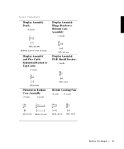
Screw Placement Display Assembly Bezel: (6 each) Display Assembly Hinge Bracket to Bottom Case Assembly: (5 each) Rubber Screw Covers (6 each) Display Assembly and Flex Cable Retention Bracket to Top Cover: (5 each) Display Assembly EMI Shield Bracket: (2 each) Palmrest to Bottom Case Assembly: (5 each) (3 each) Hybrid Cooling Fan: (2 each) (1 each) B e fo re You Be gin 13
Screw Placement Display Assembly Bezel: (6 each) Display Assembly Hinge Bracket to Bottom Case Assembly: (5 each) Rubber Screw Covers (6 each) Display Assembly and Flex Cable Retention Bracket to Top Cover: (5 each) Display Assembly EMI Shield Bracket: (2 each) Palmrest to Bottom Case Assembly: (5 each) (3 each) Hybrid Cooling Fan: (2 each) (1 each) B e fo re You Be gin 13
Service Manual
Page 15
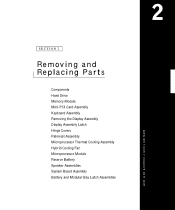
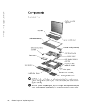
SECTION 2 Removing and Replacing Parts Components Hard Drive Memory Module Mini-PCI Card Assembly Keyboard Assembly Removing the Display Assembly Display Assembly Latch Hinge Covers Palmrest Assembly Microprocessor Thermal Cooling Assembly Hybrid Cooling Fan Microprocessor Module Reserve Battery Speaker Assemblies System Board Assembly Battery and Modular Bay Latch Assemblies www.dell.com | support.dell.com
SECTION 2 Removing and Replacing Parts Components Hard Drive Memory Module Mini-PCI Card Assembly Keyboard Assembly Removing the Display Assembly Display Assembly Latch Hinge Covers Palmrest Assembly Microprocessor Thermal Cooling Assembly Hybrid Cooling Fan Microprocessor Module Reserve Battery Speaker Assemblies System Board Assembly Battery and Modular Bay Latch Assemblies www.dell.com | support.dell.com
Service Manual
Page 16
.../antenna assembly modem and NIC connector covers fan guard modular bay device bottom case assembly memory module cover NOTICE: Only a certified service technician should perform repairs on your warranty. NOTICE: Unless otherwise noted, each procedure in this manual assumes that is not authorized by Dell is not covered by performing the removal...
.../antenna assembly modem and NIC connector covers fan guard modular bay device bottom case assembly memory module cover NOTICE: Only a certified service technician should perform repairs on your warranty. NOTICE: Unless otherwise noted, each procedure in this manual assumes that is not authorized by Dell is not covered by performing the removal...
Service Manual
Page 45
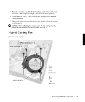
Hybrid Cooling Fan Hybrid Cooling Fan M2.5 x 5-mm screws (2) M2 x 3-mm screw (1) hybrid cooling fan Removing and Repl aci ng Part s 45 NOTICE: When reattaching the microprocessor thermal cooling assembly, tighten the captive screws in consecutive order, from the system board assembly. 3 Turn the computer over, lift the keyboard up, rotate it forward toward the front of the computer, and place it face down on the palmrest. 4 Loosen the four captive screws securing the microprocessor thermal cooling assembly. 5 Remove the microprocessor thermal cooling assembly from 1 to 4.
Hybrid Cooling Fan Hybrid Cooling Fan M2.5 x 5-mm screws (2) M2 x 3-mm screw (1) hybrid cooling fan Removing and Repl aci ng Part s 45 NOTICE: When reattaching the microprocessor thermal cooling assembly, tighten the captive screws in consecutive order, from the system board assembly. 3 Turn the computer over, lift the keyboard up, rotate it forward toward the front of the computer, and place it face down on the palmrest. 4 Loosen the four captive screws securing the microprocessor thermal cooling assembly. 5 Remove the microprocessor thermal cooling assembly from 1 to 4.
Service Manual
Page 46
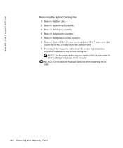
... cable is long, and can be pulled out from the system board interface connector and remove the hybrid cooling fan. www.dell.com | support.dell.com Removing the Hybrid Cooling Fan 1 Remove the hard drive. 2 Remove the keyboard assembly. 3 Remove the display assembly. 4 Remove the palmrest assembly. 5 Remove the thermal cooling assembly. 6 Remove the...
... cable is long, and can be pulled out from the system board interface connector and remove the hybrid cooling fan. www.dell.com | support.dell.com Removing the Hybrid Cooling Fan 1 Remove the hard drive. 2 Remove the keyboard assembly. 3 Remove the display assembly. 4 Remove the palmrest assembly. 5 Remove the thermal cooling assembly. 6 Remove the...
Service Manual
Page 54
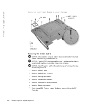
... and Replacing Parts NOTICE: To avoid ESD, ground yourself by using a wrist grounding strap or by periodically touching an unpainted metal on the computer. www.dell.com | support.dell.com Removing the System Board Assembly Screws fan guard M2.5 x 5-mm screws (9) Removing the System Board NOTICE: Disconnect the computer and any installed batteries.
... and Replacing Parts NOTICE: To avoid ESD, ground yourself by using a wrist grounding strap or by periodically touching an unpainted metal on the computer. www.dell.com | support.dell.com Removing the System Board Assembly Screws fan guard M2.5 x 5-mm screws (9) Removing the System Board NOTICE: Disconnect the computer and any installed batteries.
Service Manual
Page 55
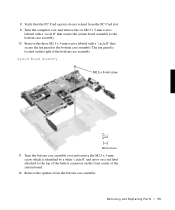
... remove the M2.5 x 5-mm screw, which is located on the right of the system board. 12 Remove the speakers from the bottom case assembly. The fan guard is identified by a white "circle B" and arrow on the front center of the bottom case assembly. System Board Assembly M2.5 x 5-mm screw 11 ...a "circle B" that secure the system board assembly to the bottom case assembly. 10 Remove the three M2.5 x 5-mm screws labeled with a "circle B" that secure the fan guard to the top of the battery connector on a red label attached to the bottom case assembly. Removing and Repl aci ng Part s 55
... remove the M2.5 x 5-mm screw, which is located on the right of the system board. 12 Remove the speakers from the bottom case assembly. The fan guard is identified by a white "circle B" and arrow on the front center of the bottom case assembly. System Board Assembly M2.5 x 5-mm screw 11 ...a "circle B" that secure the system board assembly to the bottom case assembly. 10 Remove the three M2.5 x 5-mm screws labeled with a "circle B" that secure the fan guard to the top of the battery connector on a red label attached to the bottom case assembly. Removing and Repl aci ng Part s 55
Service Manual
Page 56
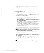
... the replacement system board. 2 Connect the right and left speaker to the replacement system board. 3 Install the replacement system board. c Replace the fan guard cover, inserting the tab into the BIOS of the replacement system board assembly. 56 Removi ng and Replacing Parts NOTE: After replacing the system...lift the front of the system board assembly out and away from the old system board. Follow the instructions on the computer. www.dell.com | support.dell.com 13 Pull the right side of bottom case assembly, next to the external headphone and microphone connectors, away from the system ...
... the replacement system board. 2 Connect the right and left speaker to the replacement system board. 3 Install the replacement system board. c Replace the fan guard cover, inserting the tab into the BIOS of the replacement system board assembly. 56 Removi ng and Replacing Parts NOTE: After replacing the system...lift the front of the system board assembly out and away from the old system board. Follow the instructions on the computer. www.dell.com | support.dell.com 13 Pull the right side of bottom case assembly, next to the external headphone and microphone connectors, away from the system ...
Service Manual
Page 59
... display-assembly top cover replacing, 35 display-feed flex cable H hard drive, 17 removing, 17 replacing, 17 hinge covers removing, 39 replacing, 40 hybrid cooling fan removing, 46 K keyboard, 23 removing, 23 replacing, 25 M memory module, 18 removing, 19 replacing, 20 microprocessor module removing, 47 replacing, 48 microprocessor thermal cooling assembly...
... display-assembly top cover replacing, 35 display-feed flex cable H hard drive, 17 removing, 17 replacing, 17 hinge covers removing, 39 replacing, 40 hybrid cooling fan removing, 46 K keyboard, 23 removing, 23 replacing, 25 M memory module, 18 removing, 19 replacing, 20 microprocessor module removing, 47 replacing, 48 microprocessor thermal cooling assembly...
System Information Guide
Page 13
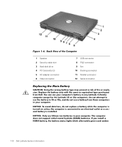
... computer is turned on unless the computer is connected to use a battery from Dell. If you install a NiMH battery, the battery status lights blink alternately green and amber. 1-10 Dell Latitude System Information Back View of the Computer 1 Speaker 2 Security cable slot 3... Hard-disk drive 4 PC Card slots (2) 5 AC adapter connector 6 Video connector 7 USB connector 8 PS/2 connector 9 Fan 10 Docking connector 11 Parallel connector 12 ...
... computer is turned on unless the computer is connected to use a battery from Dell. If you install a NiMH battery, the battery status lights blink alternately green and amber. 1-10 Dell Latitude System Information Back View of the Computer 1 Speaker 2 Security cable slot 3... Hard-disk drive 4 PC Card slots (2) 5 AC adapter connector 6 Video connector 7 USB connector 8 PS/2 connector 9 Fan 10 Docking connector 11 Parallel connector 12 ...


