Owners Manual
Page 41
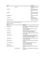
... the health of the battery. The default option is Enabled USB Wake Support Allows USB devices to the on-board network card. Table 3. The default option is Enabled USB Emulation Enable or disable the USB emulation feature. The default option is Enabled Integrated NIC Enable...computer from standby. The default option is Enabled Function Key Behavior Specifies the behavior of the computer. External USB Ports Enables or disables external USB ports. The default option is Disabled SATA Operation Change the SATA controller mode to set various functions that affect...
... the health of the battery. The default option is Enabled USB Wake Support Allows USB devices to the on-board network card. Table 3. The default option is Enabled USB Emulation Enable or disable the USB emulation feature. The default option is Enabled Integrated NIC Enable...computer from standby. The default option is Enabled Function Key Behavior Specifies the behavior of the computer. External USB Ports Enables or disables external USB ports. The default option is Disabled SATA Operation Change the SATA controller mode to set various functions that affect...
Owners Manual
Page 42
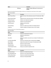
... Description Enables or disables USB debug. The default option is UEFI Add Boot Option Allows you to set an administrator password. Password Change Allows you to exit while saving changes. ...
... Description Enables or disables USB debug. The default option is UEFI Add Boot Option Allows you to set an administrator password. Password Change Allows you to exit while saving changes. ...
Owners Manual
Page 52
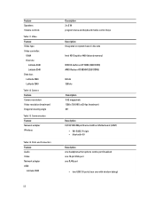
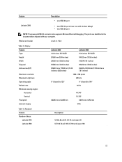
Video Feature Video type Video controller: UMA Discrete Latitude 3440 Latitude 3540 Data bus: Latitude 3440 Latitude 3540 Table 12. Feature Speakers Volume controls Table 11. Ports and Connectors Feature Audio Video Network adapter USB: Latitude 3440 52 Description 2 x 2 W program menu and keyboard media-...8226; bluetooth 4.0 Description one headphone/microphone combo port (headset) one 19-pin VGA port one RJ45 port • two USB 3.0 ports (rear one with window debug) Communication Feature Network adapter Wireless Table 14. Camera Feature Camera resolution Video resolution (maximum...
Video Feature Video type Video controller: UMA Discrete Latitude 3440 Latitude 3540 Data bus: Latitude 3440 Latitude 3540 Table 12. Feature Speakers Volume controls Table 11. Ports and Connectors Feature Audio Video Network adapter USB: Latitude 3440 52 Description 2 x 2 W program menu and keyboard media-...8226; bluetooth 4.0 Description one headphone/microphone combo port (headset) one 19-pin VGA port one RJ45 port • two USB 3.0 ports (rear one with window debug) Communication Feature Network adapter Wireless Table 14. Camera Feature Camera resolution Video resolution (maximum...
Owners Manual
Page 53
... Table 15. Keyboard Feature Number of keys: Latitude 3440 Latitude 3540 Description US 86, Brazil 87, UK 87 and Japan 90 US 102, Brazil 105, UK 103 and Japan 106 53 Feature Latitude 3540 Description • one USB 2.0 port • two USB 3.0 ports (rear one 4-in the documentation ...shipped with window debug) • two USB 2.0 port NOTE: The powered USB 3.0 connector also supports Microsoft Kernel Debugging. Media card reader...
... Table 15. Keyboard Feature Number of keys: Latitude 3440 Latitude 3540 Description US 86, Brazil 87, UK 87 and Japan 90 US 102, Brazil 105, UK 103 and Japan 106 53 Feature Latitude 3540 Description • one USB 2.0 port • two USB 3.0 ports (rear one 4-in the documentation ...shipped with window debug) • two USB 2.0 port NOTE: The powered USB 3.0 connector also supports Microsoft Kernel Debugging. Media card reader...
Setup Guide
Page 1
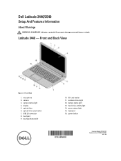
... 5. USB 2.0 connector 8. battery status light 13. keyboard 16. power button Regulatory Model: P37G, P28F Regulatory Type: P37G004, P28F004 2013 - 06 Front View 1. optical drive 6. wireless status light 12. optical-drive eject button 7. touchpad 9. camera status light 4. hard-drive activity light 14. Latitude 3440 - touchpad buttons (2) 10. power status light 15. camera 3. Dell Latitude 3440/3540...
... 5. USB 2.0 connector 8. battery status light 13. keyboard 16. power button Regulatory Model: P37G, P28F Regulatory Type: P37G004, P28F004 2013 - 06 Front View 1. optical drive 6. wireless status light 12. optical-drive eject button 7. touchpad 9. camera status light 4. hard-drive activity light 14. Latitude 3440 - touchpad buttons (2) 10. power status light 15. camera 3. Dell Latitude 3440/3540...
Setup Guide
Page 2
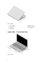
power connector 3. Front View 2 cooling vents 4. USB 3.0 connectors (2) 7. Back View 1. VGA connector 5. Front and Back View Figure 3. security cable slot 2. network connector 6. audio connector Latitude 3540 - Figure 2.
power connector 3. Front View 2 cooling vents 4. USB 3.0 connectors (2) 7. Back View 1. VGA connector 5. Front and Back View Figure 3. security cable slot 2. network connector 6. audio connector Latitude 3540 - Figure 2.
Setup Guide
Page 3
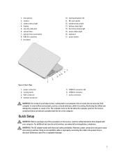
optical drive 7. USB 2.0 connector 7. audio connector WARNING: Do not block, push objects into, or allow dust to the power strip or electrical outlet may cause fire or equipment damage. 3 Restricting the airflow can damage the computer or cause a fire. For additional best practices information, see www.dell.com/regulatory_compliance WARNING: The AC adapter...
optical drive 7. USB 2.0 connector 7. audio connector WARNING: Do not block, push objects into, or allow dust to the power strip or electrical outlet may cause fire or equipment damage. 3 Restricting the airflow can damage the computer or cause a fire. For additional best practices information, see www.dell.com/regulatory_compliance WARNING: The AC adapter...
Setup Guide
Page 4
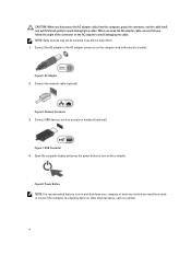
... devices may not be included if you follow the angle of the connector on the AC adapter to avoid damaging the cable. Figure 7. USB Connector 4. AC Adapter 2. Connect USB devices, such as a printer. 4 Figure 8. Network Connector 3. Connect the AC adapter to the AC adapter connector on the computer and to turn on...
... devices may not be included if you follow the angle of the connector on the AC adapter to avoid damaging the cable. Figure 7. USB Connector 4. AC Adapter 2. Connect USB devices, such as a printer. 4 Figure 8. Network Connector 3. Connect the AC adapter to the AC adapter connector on the computer and to turn on...


