Owners Manual
Page 3
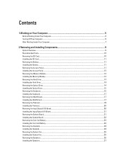
......5 Turning Off Your Computer...6 After Working Inside Your Computer...7 2 Removing and Installing Components 9 System Overview...9 Recommended Tools...10 Removing the SD Card...10 Installing the SD Card...11 Removing the Battery...11 Installing the Battery...11 Removing the Access Panel...11 Installing the Access Panel...12 Removing the Memory Module...12 Installing the Memory Module...12 Removing the Hard Drive...13 Installing the Hard Drive...14 Removing the Optical Drive...14 Installing the Optical Drive...15 Removing the Keyboard...15 Installing the Keyboard...17 Removing the WLAN Card...
......5 Turning Off Your Computer...6 After Working Inside Your Computer...7 2 Removing and Installing Components 9 System Overview...9 Recommended Tools...10 Removing the SD Card...10 Installing the SD Card...11 Removing the Battery...11 Installing the Battery...11 Removing the Access Panel...11 Installing the Access Panel...12 Removing the Memory Module...12 Installing the Memory Module...12 Removing the Hard Drive...13 Installing the Hard Drive...14 Removing the Optical Drive...14 Installing the Optical Drive...15 Removing the Keyboard...15 Installing the Keyboard...17 Removing the WLAN Card...
Owners Manual
Page 4
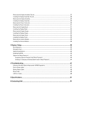
... the Display Panel...34 Installing the Display Panel...35 Removing the Camera Module...36 Installing the Camera Module...36 3 System Setup...39 Boot Sequence...39 Navigation Keys...39 System Setup Options...40 Updating the BIOS ...43 System and Setup Password...43 Assigning a System Password and Setup Password 44 Deleting or Changing an Existing System and/or Setup Password 44 4 Troubleshooting...47 Enhanced Pre-Boot System Assessment (ePSA) Diagnostics 47 Device Status Lights...47 Battery Status Lights...48 Beep Codes...48 LED Error Codes...48 5 Specifications...51 6 Contacting Dell...
... the Display Panel...34 Installing the Display Panel...35 Removing the Camera Module...36 Installing the Camera Module...36 3 System Setup...39 Boot Sequence...39 Navigation Keys...39 System Setup Options...40 Updating the BIOS ...43 System and Setup Password...43 Assigning a System Password and Setup Password 44 Deleting or Changing an Existing System and/or Setup Password 44 4 Troubleshooting...47 Enhanced Pre-Boot System Assessment (ePSA) Diagnostics 47 Device Status Lights...47 Battery Status Lights...48 Beep Codes...48 LED Error Codes...48 5 Specifications...51 6 Contacting Dell...
Owners Manual
Page 5
... connectors apart, keep them evenly aligned to avoid bending any connector pins. CAUTION: To disconnect a network cable, first unplug the cable from your work surface is connected to prevent the computer cover from the computer. 5. You should only perform troubleshooting and simple repairs as a connector on a card. Ensure that shipped with your computer and certain components may only be replaced or...
... connectors apart, keep them evenly aligned to avoid bending any connector pins. CAUTION: To disconnect a network cable, first unplug the cable from your work surface is connected to prevent the computer cover from the computer. 5. You should only perform troubleshooting and simple repairs as a connector on a card. Ensure that shipped with your computer and certain components may only be replaced or...
Owners Manual
Page 6
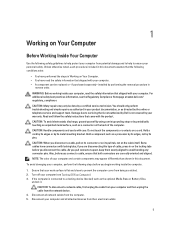
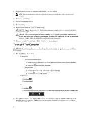
... the power button for about 6 seconds to dissipate static electricity, which could harm internal components. 11. b. Click the - or 1. If your computer and attached devices did not automatically turn off when you turn off . 6 In Windows 8: * Using a touch-enabled device: a. Click Shut Down. While you service the computer. 7. Remove any installed ExpressCards or Smart Cards from the right edge of the screen and click Settings. In Windows 7: and...
... the power button for about 6 seconds to dissipate static electricity, which could harm internal components. 11. b. Click the - or 1. If your computer and attached devices did not automatically turn off when you turn off . 6 In Windows 8: * Using a touch-enabled device: a. Click Shut Down. While you service the computer. 7. Remove any installed ExpressCards or Smart Cards from the right edge of the screen and click Settings. In Windows 7: and...
Owners Manual
Page 7
... use only the battery designed for other Dell computers. 1. Turn on your computer. Connect any cards, such as a port replicator, battery slice, or media base, and replace any telephone or network cables to your computer. Replace the battery. 4. CAUTION: To connect a network cable, first plug the cable into the network device and then plug it into the computer. 3. After Working Inside Your Computer After you complete any replacement procedure, ensure you connect any external devices, cards...
... use only the battery designed for other Dell computers. 1. Turn on your computer. Connect any cards, such as a port replicator, battery slice, or media base, and replace any telephone or network cables to your computer. Replace the battery. 4. CAUTION: To connect a network cable, first plug the cable into the network device and then plug it into the computer. 3. After Working Inside Your Computer After you complete any replacement procedure, ensure you connect any external devices, cards...
Owners Manual
Page 12
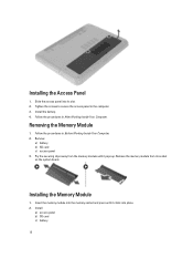
... its slot. 2. Install: a) access panel b) SD card c) battery 12 Install the battery. 4. Insert the memory module into the memory socket and press until it clicks into its socket on the system board. Remove: a) battery b) SD card c) access panel 3. Installing the Memory Module 1. Slide the access panel into place. 2. Follow the procedures in Before Working Inside Your Computer. 2. Follow the procedures in After Working Inside Your Computer. Installing the Access Panel 1. Removing the Memory Module 1. Tighten the screws to secure the access panel...
... its slot. 2. Install: a) access panel b) SD card c) battery 12 Install the battery. 4. Insert the memory module into the memory socket and press until it clicks into its socket on the system board. Remove: a) battery b) SD card c) access panel 3. Installing the Memory Module 1. Slide the access panel into place. 2. Follow the procedures in Before Working Inside Your Computer. 2. Follow the procedures in After Working Inside Your Computer. Installing the Access Panel 1. Removing the Memory Module 1. Tighten the screws to secure the access panel...
Owners Manual
Page 14
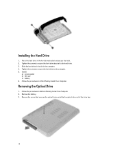
... screws to secure the hard-drive bracket to the computer. 5. Slide the hard drive in its slot in After Working Inside Your Computer. Tighten the screws to secure the hard drive to the hard drive. 3. Removing the Optical Drive 1. Follow the procedures in the hard-drive bracket and secure the latch. 2. Installing the Hard Drive 1. Remove the battery. 3. Install: a) access panel b) SD card c) battery 6. Place the hard drive in Before Working Inside Your Computer. 2. Remove the screw that...
... screws to secure the hard-drive bracket to the computer. 5. Slide the hard drive in its slot in After Working Inside Your Computer. Tighten the screws to secure the hard drive to the hard drive. 3. Removing the Optical Drive 1. Follow the procedures in the hard-drive bracket and secure the latch. 2. Installing the Hard Drive 1. Remove the battery. 3. Install: a) access panel b) SD card c) battery 6. Place the hard drive in Before Working Inside Your Computer. 2. Remove the screw that...

Owners Manual
Page 20
... the computer. 20 Connect the touchpad cable and the power-button cables to the system board. 4. Tighten the screws to secure the palmrest to the system board. 3. Remove: a) battery b) access panel c) keyboard d) palmrest 3. Installing the Palmrest 1. Flip the computer and tighten the screws to secure the palmrest to the computer and lift the I /O board to the computer. 5. Follow the procedures in Before Working Inside Your Computer...
... the computer. 20 Connect the touchpad cable and the power-button cables to the system board. 4. Tighten the screws to secure the palmrest to the system board. 3. Remove: a) battery b) access panel c) keyboard d) palmrest 3. Installing the Palmrest 1. Flip the computer and tighten the screws to secure the palmrest to the computer and lift the I /O board to the computer. 5. Follow the procedures in Before Working Inside Your Computer...
Owners Manual
Page 21
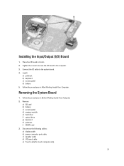
... module e) hard drive f) optical drive g) keyboard h) palmrest i) WLAN card 3. Tighten the screw to secure the I/O board to the system board. 4. Connect the I /O board in Before Working Inside Your Computer. 2. Disconnect the following cables: a) display cable b) power-connector port cable c) speaker cable d) I /O) Board 1. Install: a) palmrest b) keyboard c) access panel d) battery 5. Removing the System Board 1. Installing the Input/Output (I /O board cable e) Touch cable (for touch computer only) 21 Place the I /O cable to the computer. 3. Follow the procedures in its slot...
... module e) hard drive f) optical drive g) keyboard h) palmrest i) WLAN card 3. Tighten the screw to secure the I/O board to the system board. 4. Connect the I /O board in Before Working Inside Your Computer. 2. Disconnect the following cables: a) display cable b) power-connector port cable c) speaker cable d) I /O) Board 1. Install: a) palmrest b) keyboard c) access panel d) battery 5. Removing the System Board 1. Installing the Input/Output (I /O board cable e) Touch cable (for touch computer only) 21 Place the I /O cable to the computer. 3. Follow the procedures in its slot...
Owners Manual
Page 35
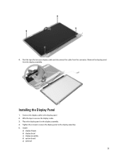
4. Place the display panel on the display assembly. 4. Installing the Display Panel 1. Tighten the screws to secure the display panel to the display panel. 2. Install: a) display hinges b) display bezel c) display assembly d) system board e) palmrest 35 Connect the display cable to the display assembly. 5. Affix the tape to secure the display cable. 3. Peel the tape that secures display cable and disconnect the cable from the display assembly. Remove the display panel from the connector.
4. Place the display panel on the display assembly. 4. Installing the Display Panel 1. Tighten the screws to secure the display panel to the display panel. 2. Install: a) display hinges b) display bezel c) display assembly d) system board e) palmrest 35 Connect the display cable to the display assembly. 5. Affix the tape to secure the display cable. 3. Peel the tape that secures display cable and disconnect the cable from the display assembly. Remove the display panel from the connector.
Owners Manual
Page 36
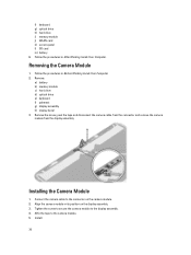
...g) optical drive h) hard drive i) memory module j) WLAN card k) access panel l) SD card m) battery 6. Removing the Camera Module 1. Remove: a) battery b) memory module c) hard drive d) optical drive e) keyboard f) palmrest g) display assembly h) display bezel 3. Installing the Camera Module 1. Install: 36 Follow the procedures in Before Working Inside Your Computer. 2. Remove the screw, peel the tape and disconnect the camera cable from the connector and remove the camera module from the display assembly. Affix the tape to the display assembly. 4. Connect the camera cable to...
...g) optical drive h) hard drive i) memory module j) WLAN card k) access panel l) SD card m) battery 6. Removing the Camera Module 1. Remove: a) battery b) memory module c) hard drive d) optical drive e) keyboard f) palmrest g) display assembly h) display bezel 3. Installing the Camera Module 1. Install: 36 Follow the procedures in Before Working Inside Your Computer. 2. Remove the screw, peel the tape and disconnect the camera cable from the connector and remove the camera module from the display assembly. Affix the tape to the display assembly. 4. Connect the camera cable to...
Owners Manual
Page 39
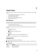
...;defined boot device order and boot directly to a specific device (for example: optical drive or hard drive). 3 System Setup System Setup enables you to access the System Setup screen. The boot-menu options are recorded but do not take effect until you can : • Change the NVRAM settings after you add or remove hardware • View the system hardware configuration • Enable or disable integrated devices • Set performance and power management thresholds • Manage your computer hardware and specify BIOS‐level options...
...;defined boot device order and boot directly to a specific device (for example: optical drive or hard drive). 3 System Setup System Setup enables you to access the System Setup screen. The boot-menu options are recorded but do not take effect until you can : • Change the NVRAM settings after you add or remove hardware • View the system hardware configuration • Enable or disable integrated devices • Set performance and power management thresholds • Manage your computer hardware and specify BIOS‐level options...
Owners Manual
Page 41
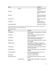
... its default value. The default option is Enabled Integrated NIC Enable or disable the power supply to wake-up the computer from standby. The default option is Enabled Function Key Behavior Specifies the behavior of the battery. Displays the type of the optical drive. External USB Ports Enables or disables external USB ports. The default option is connected. This feature is enabled only when the AC adapter is Enabled 41 Displays the model number and capacity of the AC adapter. Displays the memory installed on -board network card. Table 3. Advance Options Option...
... its default value. The default option is Enabled Integrated NIC Enable or disable the power supply to wake-up the computer from standby. The default option is Enabled Function Key Behavior Specifies the behavior of the battery. Displays the type of the optical drive. External USB Ports Enables or disables external USB ports. The default option is connected. This feature is enabled only when the AC adapter is Enabled 41 Displays the model number and capacity of the AC adapter. Displays the memory installed on -board network card. Table 3. Advance Options Option...
Owners Manual
Page 42
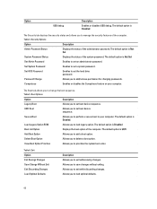
... default option is Disabled The Security tab displays the security status and allows you to your computer. Set HDD Password Enables to manage the security features of the administrator password. Password Change Allows you to add a boot option. UEFI Boot Allows you to load legacy option. The default option is UEFI Add Boot Option Allows you to add/remove permission for changing passwords. Load Legacy Option ROM Allows you to set the hard drive password. The default option is Enabled. Delete Boot Option Allows...
... default option is Disabled The Security tab displays the security status and allows you to your computer. Set HDD Password Enables to manage the security features of the administrator password. Password Change Allows you to add a boot option. UEFI Boot Allows you to load legacy option. The default option is UEFI Add Boot Option Allows you to add/remove permission for changing passwords. Load Legacy Option ROM Allows you to set the hard drive password. The default option is Enabled. Delete Boot Option Allows...
Owners Manual
Page 43
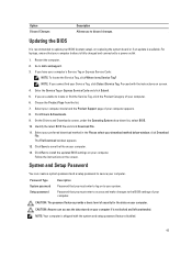
... the latest BIOS file and click Download File. 11. CAUTION: Anyone can create a system password and a setup password to your computer. Updating the BIOS It is recommended to install the updated BIOS settings on replacing the system board or if an update is not locked and left unattended. Choose the Product Type from the list. 7. On the Drivers and Downloads screen, under the Operating System drop-down list, select BIOS. 10. The File Download window appears...
... the latest BIOS file and click Download File. 11. CAUTION: Anyone can create a system password and a setup password to your computer. Updating the BIOS It is recommended to install the updated BIOS settings on replacing the system board or if an update is not locked and left unattended. Choose the Product Type from the list. 7. On the Drivers and Downloads screen, under the Operating System drop-down list, select BIOS. 10. The File Download window appears...
Owners Manual
Page 47
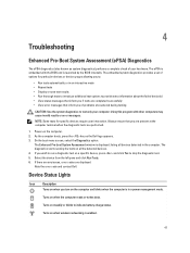
... provides a set of your computer. Using this program with the BIOS and is in a power management mode. As the computer boots, press the key as system diagnostics) performs a complete check of options for specific devices require user interaction. The diagnostics starts running the tests on the computer and blinks when the computer is launched by the BIOS internally. Note the error code and contact Dell. Device Status Lights Icon Description Turns on...
... provides a set of your computer. Using this program with the BIOS and is in a power management mode. As the computer boots, press the key as system diagnostics) performs a complete check of options for specific devices require user interaction. The diagnostics starts running the tests on the computer and blinks when the computer is launched by the BIOS internally. Note the error code and contact Dell. Device Status Lights Icon Description Turns on...
Owners Manual
Page 48
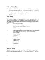
...-Day Clock test failure , Gate A20 failure , Super I/O chip failure , Keyboard controller test failure System board failure 4 RAM Read/Write failure Memory failure 5 Real-time clock power fail CMOS battery failure 6 Video BIOS test failure Video card failure 7 CPU - cache test failure Processor failure 8 Display Display failure LED Error Codes Diagnostic LED codes are communicated via the Power Button LED. Battery Status Lights If the computer is connected to your laptop. • Alternately blinking amber light with steady white...
...-Day Clock test failure , Gate A20 failure , Super I/O chip failure , Keyboard controller test failure System board failure 4 RAM Read/Write failure Memory failure 5 Real-time clock power fail CMOS battery failure 6 Video BIOS test failure Video card failure 7 CPU - cache test failure Processor failure 8 Display Display failure LED Error Codes Diagnostic LED codes are communicated via the Power Button LED. Battery Status Lights If the computer is connected to your laptop. • Alternately blinking amber light with steady white...
Owners Manual
Page 51
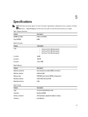
...width 64 bits and 128 bits Flash EPROM 8 MB Table 8. 5 Specifications NOTE: Offerings may vary by region. Memory Feature Memory connector Memory capacity Memory type Minimum memory Maximum memory Description two internally accessible DDR3L connectors 2 GB and 4 GB 1600 MHz (dual channel DDR3L configuration) 2 GB, 4 GB, ... information about your computer, click Start (Start icon) → Help and Support, and then select the option to 4 MB Table 9. Audio Feature Type Controller Stereo conversion Interface Description 2 channel high definition audio Realtek ALC3223 24-bit (analog to...
...width 64 bits and 128 bits Flash EPROM 8 MB Table 8. 5 Specifications NOTE: Offerings may vary by region. Memory Feature Memory connector Memory capacity Memory type Minimum memory Maximum memory Description two internally accessible DDR3L connectors 2 GB and 4 GB 1600 MHz (dual channel DDR3L configuration) 2 GB, 4 GB, ... information about your computer, click Start (Start icon) → Help and Support, and then select the option to 4 MB Table 9. Audio Feature Type Controller Stereo conversion Interface Description 2 channel high definition audio Realtek ALC3223 24-bit (analog to...
Setup Guide
Page 1
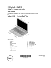
optical drive 6. touchpad buttons (2) 10. hard-drive activity light 14. Front View 1. display 5. optical-drive eject button 7. wireless status light 12. battery status light 13. microphone 2. touchpad 9. power button Regulatory Model: P37G, P28F Regulatory Type: P37G004, P28F004 2013 - 06 Latitude 3440 - power status light 15. camera 3. keyboard 16. SD card reader 11. Dell Latitude 3440/3540 Setup And Features Information About Warnings WARNING: A WARNING indicates a potential for property damage, personal injury, or death. camera status light 4. USB 2.0 ...
optical drive 6. touchpad buttons (2) 10. hard-drive activity light 14. Front View 1. display 5. optical-drive eject button 7. wireless status light 12. battery status light 13. microphone 2. touchpad 9. power button Regulatory Model: P37G, P28F Regulatory Type: P37G004, P28F004 2013 - 06 Latitude 3440 - power status light 15. camera 3. keyboard 16. SD card reader 11. Dell Latitude 3440/3540 Setup And Features Information About Warnings WARNING: A WARNING indicates a potential for property damage, personal injury, or death. camera status light 4. USB 2.0 ...
Setup Guide
Page 3
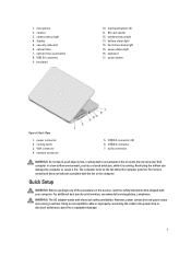
camera status light 4. touchpad 10. hard-drive status light 15. power button Figure 4. cooling vents 3. network connector 5. USB 2.0 connector 7. The computer turns on the fan when the computer gets hot. Fan noise is running. optical drive 7. touchpad buttons (2) 11. keyboard 17. Quick Setup WARNING: Before you begin any of the procedures in the air vents. wireless status light 13. battery status light 14. power connector 2. audio connector WARNING: Do not block, push objects into, or allow dust...
camera status light 4. touchpad 10. hard-drive status light 15. power button Figure 4. cooling vents 3. network connector 5. USB 2.0 connector 7. The computer turns on the fan when the computer gets hot. Fan noise is running. optical drive 7. touchpad buttons (2) 11. keyboard 17. Quick Setup WARNING: Before you begin any of the procedures in the air vents. wireless status light 13. battery status light 14. power connector 2. audio connector WARNING: Do not block, push objects into, or allow dust...


