
Installation Guide
Page 3
......22 To install the S5000 system, Dell Networking recommends completing the installation procedures in the order presented here...22 Attaching the Mounting Brackets...22 Rack Mounting Safety Considerations...23 Installing the S5000 Chassis into a 4-Post Rack or Cabinet 24 Rack Grounding...24 Important Points to Remember for Installing an Ethernet Module 24 Installing an...
......22 To install the S5000 system, Dell Networking recommends completing the installation procedures in the order presented here...22 Attaching the Mounting Brackets...22 Rack Mounting Safety Considerations...23 Installing the S5000 Chassis into a 4-Post Rack or Cabinet 24 Rack Grounding...24 Important Points to Remember for Installing an Ethernet Module 24 Installing an...

Installation Guide
Page 4
...Securing Power Cables...35 Replacing an AC or DC Power Supply...36 Important Points to Remember for Installing a Fan Module 36 Installing a Fan Module...37 Replacing a Fan Module...37 Installing the SFP+ and QSFP+ Optics...37 Splitting QSFP+ Ports to SFP+ Ports...38 Important Points to... Remember...38 Connecting the Stacking Ports (Optional)...38 Connecting Two S5000 Systems...40 Connecting Three S5000 Systems...40 Supplying Power and ...
...Securing Power Cables...35 Replacing an AC or DC Power Supply...36 Important Points to Remember for Installing a Fan Module 36 Installing a Fan Module...37 Replacing a Fan Module...37 Installing the SFP+ and QSFP+ Optics...37 Splitting QSFP+ Ports to SFP+ Ports...38 Important Points to... Remember...38 Connecting the Stacking Ports (Optional)...38 Connecting Two S5000 Systems...40 Connecting Three S5000 Systems...40 Supplying Power and ...

Installation Guide
Page 5
... this Guide This guide provides site preparation recommendations, and step-by-step procedures for rack mounting, installing and replacing pluggable modules, and connecting to the FTOS Command Line Reference Guide for access to laser radiation and do not stare into open apertures... visit iSupport (registration for the S5000 Switch. WARNING: When no cable is required): http://www.dell.com/support/manuals. 5 After you install and power up of the S5000, for software configuration information, refer to the FTOS Configuration Guide for the S5000 Switch and for Command Line Interface...
... this Guide This guide provides site preparation recommendations, and step-by-step procedures for rack mounting, installing and replacing pluggable modules, and connecting to the FTOS Command Line Reference Guide for access to laser radiation and do not stare into open apertures... visit iSupport (registration for the S5000 Switch. WARNING: When no cable is required): http://www.dell.com/support/manuals. 5 After you install and power up of the S5000, for software configuration information, refer to the FTOS Configuration Guide for the S5000 Switch and for Command Line Interface...

Installation Guide
Page 7
... ToR switch form factor. It is purpose-built to the FTOS Configuration Guide for the S5000 Switch, which is part of Dell Networking's S-Series switches for flexible configuration. 7 The S5000 supports Data Center Bridging (ETS/PFC/DCBX), FCoE Transit (FIP Snooping), NPIV Proxy Gateway ... small computer system interface (iSCSI) storage traffic. The S5000 delivers Fibre Channel over Ethernet (FCoE) and Fibre Channel (FC) capability in the same box. The S5000 also provides aggregation and convergence functionality using pluggable modules for Data Center Top of Rack (ToR) switches....
... ToR switch form factor. It is purpose-built to the FTOS Configuration Guide for the S5000 Switch, which is part of Dell Networking's S-Series switches for flexible configuration. 7 The S5000 supports Data Center Bridging (ETS/PFC/DCBX), FCoE Transit (FIP Snooping), NPIV Proxy Gateway ... small computer system interface (iSCSI) storage traffic. The S5000 delivers Fibre Channel over Ethernet (FCoE) and Fibre Channel (FC) capability in the same box. The S5000 also provides aggregation and convergence functionality using pluggable modules for Data Center Top of Rack (ToR) switches....

Installation Guide
Page 9
... AC or DC power cords for instructions. You can install the Ethernet modules in any item is missing or damaged, contact your ordered items. For example, if you have received your Dell Networking representative or reseller for AC or DC units (country/region specific)... 0, 1, 2, and 3 on a clean, flat surface and cut all straps securing the container. 2. Verify that you order one S5000 switch, the following items are included. Carefully remove all packing material. 5. The I /O Modules (according to order) • Two Blanks • One RJ-45 to Figure 2. 3 Unpacking the Switch The...
... AC or DC power cords for instructions. You can install the Ethernet modules in any item is missing or damaged, contact your ordered items. For example, if you have received your Dell Networking representative or reseller for AC or DC units (country/region specific)... 0, 1, 2, and 3 on a clean, flat surface and cut all straps securing the container. 2. Verify that you order one S5000 switch, the following items are included. Carefully remove all packing material. 5. The I /O Modules (according to order) • Two Blanks • One RJ-45 to Figure 2. 3 Unpacking the Switch The...

Installation Guide
Page 10
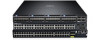
... power up the system. 10 Install the power supplies. 6. Utility panel 3. Attach the mounting brackets. 2. Install the S5000 chassis into a 4-post rack or cabinet. 3. Install the fan modules. 8. Secure the power cables. 7. I /O and Utility Panels 1. Figure 1. S5000 I /O panel 2. Install the Ethernet and/or Fibre Channel modules (Fibre Channel module must be installed only in slot 0). 5.
... power up the system. 10 Install the power supplies. 6. Utility panel 3. Attach the mounting brackets. 2. Install the S5000 chassis into a 4-post rack or cabinet. 3. Install the fan modules. 8. Secure the power cables. 7. I /O and Utility Panels 1. Figure 1. S5000 I /O panel 2. Install the Ethernet and/or Fibre Channel modules (Fibre Channel module must be installed only in slot 0). 5.

Installation Guide
Page 11
... 4 × 10GbE mode) NOTE: The LED displays for pluggable modules are on the Utility panel. 11 Slot 0 (supports Ethernet and Fibre Channel modules) 2. Slot 2 (supports only Ethernet modules) 4. The I /O Panel 1. S5000 I /O panel includes: • Pluggable Modules - 12-Port Ethernet Module (1G/10G speeds) - 12-Port Fibre Channel Module (2G/4G/8G speeds) • 4 × 40GbE QSFP+ Ports...
... 4 × 10GbE mode) NOTE: The LED displays for pluggable modules are on the Utility panel. 11 Slot 0 (supports Ethernet and Fibre Channel modules) 2. Slot 2 (supports only Ethernet modules) 4. The I /O Panel 1. S5000 I /O panel includes: • Pluggable Modules - 12-Port Ethernet Module (1G/10G speeds) - 12-Port Fibre Channel Module (2G/4G/8G speeds) • 4 × 40GbE QSFP+ Ports...

Installation Guide
Page 12
... I/O to Utility and Utility to I /O PSUs are field replaceable. Slot 2 (for PSU 0) 2. Slot 3 (for Fan Module 0) 3. Grab Handles Power Supplies The S5000 supports two hot-swappable PSUs. NOTE: The PSUs must be installed at the customer site. 12 To ensure power redundancy and adequate ...replace one PSU while the other PSU is running without disrupting traffic. S5000 Power Supplies and Fan Modules 1. Fans The S5000 supports two fan trays with fan airflow from I/O to Utility or Utility to I /O airflows in a single S5000 chassis. All fans and PSUs in a configuration must be in the ...
... I/O to Utility and Utility to I /O PSUs are field replaceable. Slot 2 (for PSU 0) 2. Slot 3 (for Fan Module 0) 3. Grab Handles Power Supplies The S5000 supports two hot-swappable PSUs. NOTE: The PSUs must be installed at the customer site. 12 To ensure power redundancy and adequate ...replace one PSU while the other PSU is running without disrupting traffic. S5000 Power Supplies and Fan Modules 1. Fans The S5000 supports two fan trays with fan airflow from I/O to Utility or Utility to I /O airflows in a single S5000 chassis. All fans and PSUs in a configuration must be in the ...

Installation Guide
Page 13
... mode. The following table lists the LED definitions for the S5000 Switch. The S5000 supports the following figure, the S5000 includes LED displays on the power supplies are solid green. The valid port numbers for pluggable modules on the S5000 I /O panel. For more information about these options, refer... to the FTOS Command Line Reference Guide and FTOS Configuration Guide for the S5000 system. 13 When the S5000 powers up or reloads, the status LED ...
... mode. The following table lists the LED definitions for the S5000 Switch. The S5000 supports the following figure, the S5000 includes LED displays on the power supplies are solid green. The valid port numbers for pluggable modules on the S5000 I /O panel. For more information about these options, refer... to the FTOS Command Line Reference Guide and FTOS Configuration Guide for the S5000 system. 13 When the S5000 powers up or reloads, the status LED ...

Installation Guide
Page 15
Port link/activity LED 3. Ethernet Port/Module LEDs Label Port locator beacon LED LED Color/Display • Off Description • No activity 15 Label Master LED PSU status LED Fan status LED ... in Stacking Standby mode • Switch in Stacking Member mode • Normal operation • Power not present • Normal operation • Power not present Figure 7. Module locator beacon LED 4. Module status LED NOTE: The downward and upward pointing triangles denote the lower and upper port LEDs respectively. Port locator beacon LED...
Port link/activity LED 3. Ethernet Port/Module LEDs Label Port locator beacon LED LED Color/Display • Off Description • No activity 15 Label Master LED PSU status LED Fan status LED ... in Stacking Standby mode • Switch in Stacking Member mode • Normal operation • Power not present • Normal operation • Power not present Figure 7. Module locator beacon LED 4. Module status LED NOTE: The downward and upward pointing triangles denote the lower and upper port LEDs respectively. Port locator beacon LED...

Installation Guide
Page 16
...8226; Green solid • Green blinking • Off • Blue • Off • Green solid • Yellow Table 3. Fibre Channel Port/Module LEDs Label LED Color/Display Port locator beacon LED • Off • Blue • Green Port link/activity LED • Off • Green ...solid • Green blinking Module locator beacon LED Module status LED • Off • Green • Off • Green solid • Yellow Description • Port beacon/locator •...
...8226; Green solid • Green blinking • Off • Blue • Off • Green solid • Yellow Table 3. Fibre Channel Port/Module LEDs Label LED Color/Display Port locator beacon LED • Off • Blue • Green Port link/activity LED • Off • Green ...solid • Green blinking Module locator beacon LED Module status LED • Off • Green • Off • Green solid • Yellow Description • Port beacon/locator •...

Installation Guide
Page 17
Figure 8. QSFP+ Port LEDs 1. Port link/activity LED Table 4. 40GbE Port/Module LEDs Label Port link/activity LED LED Color/Display • Off • Green solid • Green blinking Description • No link or interface disabled • Link present and interface enabled • Port has activity 17
Figure 8. QSFP+ Port LEDs 1. Port link/activity LED Table 4. 40GbE Port/Module LEDs Label Port link/activity LED LED Color/Display • Off • Green solid • Green blinking Description • No link or interface disabled • Link present and interface enabled • Port has activity 17

Installation Guide
Page 21
... Considerations • Installing the S5000 Chassis into a 4-post rack or cabinet • Rack Grounding • Important Points to Remember for Installing an Ethernet Module • Installing an Ethernet Module • Replacing an Ethernet Module • Important Points to Remember for Installing a Fan Module • Installing a Fibre-Channel Module • Replacing a Fibre-Channel Module • Important Points to...
... Considerations • Installing the S5000 Chassis into a 4-post rack or cabinet • Rack Grounding • Important Points to Remember for Installing an Ethernet Module • Installing an Ethernet Module • Replacing an Ethernet Module • Important Points to Remember for Installing a Fan Module • Installing a Fibre-Channel Module • Replacing a Fibre-Channel Module • Important Points to...

Installation Guide
Page 22
...chassis. 1. NOTE: For proper ventilation, position the S5000 chassis in an environment as free as possible from dust...mounted before you install the power supply modules. • Cabling is away from other particles causing contaminant...occur if components are mishandled. Avoid dropping the S5000 chassis or its components. As with all electrical...-preventive wrist or heel ground strap when handling the S5000 and its field replaceable units. Slide the mounting brackets...for rack or cabinet installation. Attaching the Mounting Brackets The S5000 is shipped with mounting brackets (rack ears) and the ...
...chassis. 1. NOTE: For proper ventilation, position the S5000 chassis in an environment as free as possible from dust...mounted before you install the power supply modules. • Cabling is away from other particles causing contaminant...occur if components are mishandled. Avoid dropping the S5000 chassis or its components. As with all electrical...-preventive wrist or heel ground strap when handling the S5000 and its field replaceable units. Slide the mounting brackets...for rack or cabinet installation. Attaching the Mounting Brackets The S5000 is shipped with mounting brackets (rack ears) and the ...

Installation Guide
Page 24
... Bracket Rack Grounding When you install or replace a module when the system is earth ground. If you prepare your area. Screws 2. 4-Post Rack or Cabinet 3. Front Rack Installation 1. Installing the S5000 Chassis into a 4-Post Rack or Cabinet NOTE: Dell Networking recommends that one person hold the S5000 chassis in place while a second person attaches...
... Bracket Rack Grounding When you install or replace a module when the system is earth ground. If you prepare your area. Screws 2. 4-Post Rack or Cabinet 3. Front Rack Installation 1. Installing the S5000 Chassis into a 4-Post Rack or Cabinet NOTE: Dell Networking recommends that one person hold the S5000 chassis in place while a second person attaches...

Installation Guide
Page 25
... occur if components are inscribed on the front of the module. Always wear an ESDpreventive wrist or heel ground strap when handling the S5000 and its components. Part name and Port number on the Ethernet module to the attached module. 25 Connect any network interface cables to slide it into... the switch module slot. 2. Instead, you must power down the switch ...
... occur if components are inscribed on the front of the module. Always wear an ESDpreventive wrist or heel ground strap when handling the S5000 and its components. Part name and Port number on the Ethernet module to the attached module. 25 Connect any network interface cables to slide it into... the switch module slot. 2. Instead, you must power down the switch ...

Installation Guide
Page 26
... before removing and replacing a Fibre Channel module. • Although the handle and port numbering may have: - If you must insert the Fibre Channel module only in a catastrophic failure. • The S5000 does not support the hot swapping of the module. 26 The part number is powered up... . Installing an Ethernet Module 1. Instead, you install or replace a module when the system is written on the ...
... before removing and replacing a Fibre Channel module. • Although the handle and port numbering may have: - If you must insert the Fibre Channel module only in a catastrophic failure. • The S5000 does not support the hot swapping of the module. 26 The part number is powered up... . Installing an Ethernet Module 1. Instead, you install or replace a module when the system is written on the ...

Installation Guide
Page 27
... and Port number on the handle as shown below. Use the grab handle on the Fibre Channel module to the attached module. 27 Always wear an ESDpreventive wrist or heel ground strap when handling the S5000 and its components. Part Name 2. WARNING: Electrostatic discharge (ESD) damage can occur if components are inscribed on...
... and Port number on the handle as shown below. Use the grab handle on the Fibre Channel module to the attached module. 27 Always wear an ESDpreventive wrist or heel ground strap when handling the S5000 and its components. Part Name 2. WARNING: Electrostatic discharge (ESD) damage can occur if components are inscribed on...
Installation Guide
Page 28
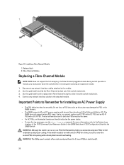
... switch operations. The S5000 does not support mixing PSU types, that is, you must be sure to run on the replacement Fibre-Channel module to 3. If the switch needs to cover the second PSU slot opening with only one PSU, Dell Networking highly recommends using two PSUs for Installing an AC ... PSU for both the PSUs must power down the switch before removing and replacing an expansion module. 1. Do not force a PSU into a slot as this action may damage the PSU or the S5000 chassis. • The S5000 supports AC and DC power supplies with a DC-R PSU. Use the grab handle to ...
... switch operations. The S5000 does not support mixing PSU types, that is, you must be sure to run on the replacement Fibre-Channel module to 3. If the switch needs to cover the second PSU slot opening with only one PSU, Dell Networking highly recommends using two PSUs for Installing an AC ... PSU for both the PSUs must power down the switch before removing and replacing an expansion module. 1. Do not force a PSU into a slot as this action may damage the PSU or the S5000 chassis. • The S5000 supports AC and DC power supplies with a DC-R PSU. Use the grab handle to ...

Installation Guide
Page 34
... clamp the ferrite onto both cables. 34 Wrap the DC power and return cables around the ferrite bead twice if two turns of the master module. Grounding Wire NOTE: The system is correctly installed. NOTE: Ensure that the socket-outlet is located/installed near the equipment and is connected between the...
... clamp the ferrite onto both cables. 34 Wrap the DC power and return cables around the ferrite bead twice if two turns of the master module. Grounding Wire NOTE: The system is correctly installed. NOTE: Ensure that the socket-outlet is located/installed near the equipment and is connected between the...


