
Installation Guide
Page 3
Contents 1 About this Guide...5 Related Publications...5 2 Introduction...7 Product Description...7 3 Unpacking the Switch...9 Important Points Before You Continue...9 Hardware Installation Overview...10 4 Hardware Overview...11 I/O Panel...11 Utility Panel...12 Power ...Site Selection...19 Cabinet Placement...19 Storing Components...20 6 Installation...21 Before You Begin...21 Install the S5000 Chassis in a Rack or Cabinet...22 To install the S5000 system, Dell Networking recommends completing the installation procedures in the order presented here...22 Attaching the Mounting Brackets...22 Rack...
Contents 1 About this Guide...5 Related Publications...5 2 Introduction...7 Product Description...7 3 Unpacking the Switch...9 Important Points Before You Continue...9 Hardware Installation Overview...10 4 Hardware Overview...11 I/O Panel...11 Utility Panel...12 Power ...Site Selection...19 Cabinet Placement...19 Storing Components...20 6 Installation...21 Before You Begin...21 Install the S5000 Chassis in a Rack or Cabinet...22 To install the S5000 system, Dell Networking recommends completing the installation procedures in the order presented here...22 Attaching the Mounting Brackets...22 Rack...

Installation Guide
Page 5
... Configuration Guide for the S5000 Switch • FTOS Command Line Reference Guide for the S5000 Switch • FTOS Release Notes for the S5000 Switch NOTE: For the most recent documentation and software, visit iSupport (registration for the S5000 Switch. CAUTION: To avoid ...S5000, refer to laser radiation and do not stare into open apertures. Read this guide before servicing. WARNING: This equipment contains optical transceivers, which comply with the limits of the optical transceiver ports. This equipment contains two power cords. WARNING: When no cable is required): http://www.dell...
... Configuration Guide for the S5000 Switch • FTOS Command Line Reference Guide for the S5000 Switch • FTOS Release Notes for the S5000 Switch NOTE: For the most recent documentation and software, visit iSupport (registration for the S5000 Switch. CAUTION: To avoid ...S5000, refer to laser radiation and do not stare into open apertures. Read this guide before servicing. WARNING: This equipment contains optical transceivers, which comply with the limits of the optical transceiver ports. This equipment contains two power cords. WARNING: When no cable is required): http://www.dell...

Installation Guide
Page 7
...; Site Preparations • Installation • Technical Specifications • Agency Compliance • Technical Support Product Description The S5000 is purpose-built to the FTOS Configuration Guide for the S5000 Switch, which is available on the Dell Support website at http://support.dell.com/manuals. 2 Introduction This document provides basic information about how to configure and monitor...
...; Site Preparations • Installation • Technical Specifications • Agency Compliance • Technical Support Product Description The S5000 is purpose-built to the FTOS Configuration Guide for the S5000 Switch, which is available on the Dell Support website at http://support.dell.com/manuals. 2 Introduction This document provides basic information about how to configure and monitor...

Installation Guide
Page 9
...ports on a secure and clean surface. 4. You can insert Power supply units (PSUs) only in multiple boxes. 3 Unpacking the Switch The S5000 and its components. • One S5000 switch • Two Fans • Two Power Supplies (either AC or DC) • One rail kit (#1 and #2 Phillips screwdrivers ... to Figure 2. WARNING: If any item is missing or damaged, contact your ordered items. For example, if you have received your Dell Networking representative or reseller for AC or DC units (country/region specific) • Getting Started Guide • Safety and Regulatory Information ...
...ports on a secure and clean surface. 4. You can insert Power supply units (PSUs) only in multiple boxes. 3 Unpacking the Switch The S5000 and its components. • One S5000 switch • Two Fans • Two Power Supplies (either AC or DC) • One rail kit (#1 and #2 Phillips screwdrivers ... to Figure 2. WARNING: If any item is missing or damaged, contact your ordered items. For example, if you have received your Dell Networking representative or reseller for AC or DC units (country/region specific) • Getting Started Guide • Safety and Regulatory Information ...

Installation Guide
Page 11
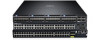
...supports only Ethernet modules) 4. Four 40GbE QSFP+ ports (each port ALSO supports 4 × 10GbE mode) NOTE: The LED displays for out-of the chassis. I /O panel. S5000 I /O panel includes: • Pluggable Modules - 12-Port Ethernet Module (1G/10G speeds) - 12-Port Fibre Channel Module (2G/4G/8G speeds) • 4 ×... I /O Panel All fixed data ports (4 × 40GbE quad small form-factor pluggable plus [QSFP+] ports) and the four slots for the S5000. The system also provides one DB9 RS-232 console port with 640Gbps switching bandwidth. Slot 3 (supports only Ethernet modules) 5.
...supports only Ethernet modules) 4. Four 40GbE QSFP+ ports (each port ALSO supports 4 × 10GbE mode) NOTE: The LED displays for out-of the chassis. I /O panel. S5000 I /O panel includes: • Pluggable Modules - 12-Port Ethernet Module (1G/10G speeds) - 12-Port Fibre Channel Module (2G/4G/8G speeds) • 4 ×... I /O Panel All fixed data ports (4 × 40GbE quad small form-factor pluggable plus [QSFP+] ports) and the four slots for the S5000. The system also provides one DB9 RS-232 console port with 640Gbps switching bandwidth. Slot 3 (supports only Ethernet modules) 5.

Installation Guide
Page 12
...0 (for PSU 1) 5. Slot 1 (for Fan Module 1) 4. Slot 2 (for Fan Module 0) 3. Figure 3. S5000 Power Supplies and Fan Modules 1. Do not mix I/O to Utility and Utility to I /O. All fans and PSUs in the switch. The fans must be installed at the customer site. 12 Grab Handles Power Supplies The... S5000 supports two hot-swappable PSUs. To ensure power redundancy and adequate cooling, install two power supplies in...
...0 (for PSU 1) 5. Slot 1 (for Fan Module 1) 4. Slot 2 (for Fan Module 0) 3. Figure 3. S5000 Power Supplies and Fan Modules 1. Do not mix I/O to Utility and Utility to I /O. All fans and PSUs in the switch. The fans must be installed at the customer site. 12 Grab Handles Power Supplies The... S5000 supports two hot-swappable PSUs. To ensure power redundancy and adequate cooling, install two power supplies in...

Installation Guide
Page 13
...mode. As shown in several ways, including LEDs and through the CLI show commands and with simple network management protocol (SNMP). When the S5000 powers up or reloads, the status LED on the I/O and Utility side of the chassis. Port Numbering Convention Even-numbered ports are ...-unit numbers (from 0 to the FTOS Command Line Reference Guide and FTOS Configuration Guide for the S5000 Switch. Figure 4. You can view S5000 status information in the following figure, the S5000 includes LED displays on the power supplies are solid green. The following possible modules: • 12...
...mode. As shown in several ways, including LEDs and through the CLI show commands and with simple network management protocol (SNMP). When the S5000 powers up or reloads, the status LED on the I/O and Utility side of the chassis. Port Numbering Convention Even-numbered ports are ...-unit numbers (from 0 to the FTOS Command Line Reference Guide and FTOS Configuration Guide for the S5000 Switch. Figure 4. You can view S5000 status information in the following figure, the S5000 includes LED displays on the power supplies are solid green. The following possible modules: • 12...

Installation Guide
Page 15
...; Off • Green solid • Off Description • System is booting • System in card problem state • Switch in Stacking Master mode OR Switch in Standalone mode • Switch in Stacking Standby mode • Switch in Stacking Member mode • Normal operation • Power not present • Normal operation • Power not present...
...; Off • Green solid • Off Description • System is booting • System in card problem state • Switch in Stacking Master mode OR Switch in Standalone mode • Switch in Stacking Standby mode • Switch in Stacking Member mode • Normal operation • Power not present • Normal operation • Power not present...

Installation Guide
Page 21
... in a Rack or Cabinet • Attaching the Mounting Brackets • Rack Mounting Safety Considerations • Installing the S5000 Chassis into a 4-post rack or cabinet • Rack Grounding • Important Points to Remember for Installing an Ethernet Module • ...SFP+ and QSFP+ Optics • Splitting QSFP+ Ports to SFP+ Ports • Connecting the Stacking Ports (Optional) • Connecting Two S5000 Systems • Connecting Three S5000 Systems • Supplying Power and Powering Up the System • Hot-Swapping Units in a Stack • Tips Before You Begin Before ...
... in a Rack or Cabinet • Attaching the Mounting Brackets • Rack Mounting Safety Considerations • Installing the S5000 Chassis into a 4-post rack or cabinet • Rack Grounding • Important Points to Remember for Installing an Ethernet Module • ...SFP+ and QSFP+ Optics • Splitting QSFP+ Ports to SFP+ Ports • Connecting the Stacking Ports (Optional) • Connecting Two S5000 Systems • Connecting Three S5000 Systems • Supplying Power and Powering Up the System • Hot-Swapping Units in a Stack • Tips Before You Begin Before ...

Installation Guide
Page 22
... (12.7 cm) of clearance around the unit does not exceed 104°F (40°C). Install the S5000 Chassis in a Rack or Cabinet To install the S5000 system, Dell Networking recommends completing the installation procedures in an equipment rack (or cabinet) with mounting brackets (rack ears) ...and the required screws (eight screws) for cabling. • Airflow around the switch and through the vents is installed...
... (12.7 cm) of clearance around the unit does not exceed 104°F (40°C). Install the S5000 Chassis in a Rack or Cabinet To install the S5000 system, Dell Networking recommends completing the installation procedures in an equipment rack (or cabinet) with mounting brackets (rack ears) ...and the required screws (eight screws) for cabling. • Airflow around the switch and through the vents is installed...

Installation Guide
Page 23
... Install the equipment in the downward position. Holding Bracket (factory installed) Rack Mounting Safety Considerations You may either place the switch on the unit. Stabilize racks in a closed rack assembly, the operating temperature of the equipment is required to ensure cool... air intake and to represent a specific switch. 23 Overloaded power sources and extension cords present fire and shock hazards. • Elevated ambient temperature - Do not exceed your Safety...
... Install the equipment in the downward position. Holding Bracket (factory installed) Rack Mounting Safety Considerations You may either place the switch on the unit. Stabilize racks in a closed rack assembly, the operating temperature of the equipment is required to ensure cool... air intake and to represent a specific switch. 23 Overloaded power sources and extension cords present fire and shock hazards. • Elevated ambient temperature - Do not exceed your Safety...

Installation Guide
Page 25
...is written on the front of the module. Always wear an ESDpreventive wrist or heel ground strap when handling the S5000 and its components. Instead, you must power down the switch before removing and replacing an Ethernet module. Figure 11. Part Name 2. A smaller handle that is written on the... handle, as shown in the following figure: NOTE: A blue color release latch indicates that the Ethernet module supports hot swapping during switch operations. Part name and Port number on the Ethernet module to the attached module. 25 Connect any network interface cables to slide it into...
...is written on the front of the module. Always wear an ESDpreventive wrist or heel ground strap when handling the S5000 and its components. Instead, you must power down the switch before removing and replacing an Ethernet module. Figure 11. Part Name 2. A smaller handle that is written on the... handle, as shown in the following figure: NOTE: A blue color release latch indicates that the Ethernet module supports hot swapping during switch operations. Part name and Port number on the Ethernet module to the attached module. 25 Connect any network interface cables to slide it into...

Installation Guide
Page 26
... an Ethernet Module NOTE: S5000 does not support the hot swapping of the switch module slot. 3. Use the grab handle to Remember for Installing a Fibre Channel Module • You must insert the Fibre Channel module only in a catastrophic failure. • The S5000 does not support the hot... swapping of the handle. - Important Points to slide the Ethernet module out of an Ethernet pluggable module during switch operations. A larger handle that is half the size and does not ...
... an Ethernet Module NOTE: S5000 does not support the hot swapping of the switch module slot. 3. Use the grab handle to Remember for Installing a Fibre Channel Module • You must insert the Fibre Channel module only in a catastrophic failure. • The S5000 does not support the hot... swapping of the handle. - Important Points to slide the Ethernet module out of an Ethernet pluggable module during switch operations. A larger handle that is half the size and does not ...

Installation Guide
Page 27
... handle on the Fibre Channel Module Handle 1. Part Name 2. Figure 13. Always wear an ESDpreventive wrist or heel ground strap when handling the S5000 and its components. NOTE: The part name and port number of a Fibre Channel module are mishandled. Port Number Installing a Fibre Channel Module ...1. Connect any network interface cables to slide it into the switch module slot. 2. WARNING: Electrostatic discharge (ESD) damage can occur if components are inscribed on the handle as shown below.
... handle on the Fibre Channel Module Handle 1. Part Name 2. Figure 13. Always wear an ESDpreventive wrist or heel ground strap when handling the S5000 and its components. NOTE: The part name and port number of a Fibre Channel module are mishandled. Port Number Installing a Fibre Channel Module ...1. Connect any network interface cables to slide it into the switch module slot. 2. WARNING: Electrostatic discharge (ESD) damage can occur if components are inscribed on the handle as shown below.
Installation Guide
Page 28
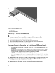
... blank plate to I /O to Utility and Utility to avoid overheating. Fibre Channel Module Replacing a Fibre-Channel Module NOTE: S5000 does not support the hot swapping of the switch module slot. 3. Instead, you cannot replace an AC PSU with a DC PSU and an AC-R PSU with two air-...panel consists of the FTOS Command Line Reference Guide for the S5000 Switch and FTOS Configuration Guide for the S5000 Switch. Figure 14. Release latch 2. Do not force a PSU into the switch module slot. 4. Use the grab handle on one PSU, Dell Networking highly recommends using two PSUs for a time, be...
... blank plate to I /O to Utility and Utility to avoid overheating. Fibre Channel Module Replacing a Fibre-Channel Module NOTE: S5000 does not support the hot swapping of the switch module slot. 3. Instead, you cannot replace an AC PSU with a DC PSU and an AC-R PSU with two air-...panel consists of the FTOS Command Line Reference Guide for the S5000 Switch and FTOS Configuration Guide for the S5000 Switch. Figure 14. Release latch 2. Do not force a PSU into the switch module slot. 4. Use the grab handle on one PSU, Dell Networking highly recommends using two PSUs for a time, be...

Installation Guide
Page 29
Always wear an ESDpreventive wrist or heel ground strap when handling the S5000 and its components. Remove the PSU from the switch PSU to the external power source (the AC wall outlet). 29 Avoid installing the switch upside down : 00:02:19: %S5000:0 %CHMGR-2-PSU_TYPE_AIRFLOW_MISMATCH: Mismatching PSU airflow detected. WARNING: Electrostatic discharge (ESD) damage can...
Always wear an ESDpreventive wrist or heel ground strap when handling the S5000 and its components. Remove the PSU from the switch PSU to the external power source (the AC wall outlet). 29 Avoid installing the switch upside down : 00:02:19: %S5000:0 %CHMGR-2-PSU_TYPE_AIRFLOW_MISMATCH: Mismatching PSU airflow detected. WARNING: Electrostatic discharge (ESD) damage can...

Installation Guide
Page 30
... for both the PSUs must be properly grounded. Important Points to I /O to Utility and Utility to Remember for the S5000 Switch. 30 Position this action may damage the PSU or the S5000 chassis. • The S5000 supports AC and DC power supplies with a DC-R PSU. When you service the power supply slots. CAUTION: Use.... NOTE: Ensure that is powered-up as soon as the main disconnect device on the bottom of the FTOS Command Line Reference Guide for the S5000 Switch and FTOS Configuration Guide for Installing a DC Power Supply • When using the second PSU.
... for both the PSUs must be properly grounded. Important Points to I /O to Utility and Utility to Remember for the S5000 Switch. 30 Position this action may damage the PSU or the S5000 chassis. • The S5000 supports AC and DC power supplies with a DC-R PSU. When you service the power supply slots. CAUTION: Use.... NOTE: Ensure that is powered-up as soon as the main disconnect device on the bottom of the FTOS Command Line Reference Guide for the S5000 Switch and FTOS Configuration Guide for Installing a DC Power Supply • When using the second PSU.

Installation Guide
Page 31
... edge connector is expelled from the PSU and a blue label indicates that Dell Networking did not authorize is not covered by your warranty. 1. Avoid installing the switch upside down : 00:02:19: %S5000:0 %CHMGR-2-PSU_TYPE_AIRFLOW_MISMATCH: Mismatching PSU airflow detected. The power supplies and fans must... color strap. WARNING: Electrostatic discharge (ESD) damage can run with only one PSU, Dell Networking highly recommends using a #6-32 nut equipped with a locking washer. 31 If the switch needs to run on the back of copper wire. 2. The airflow directions are mishandled....
... edge connector is expelled from the PSU and a blue label indicates that Dell Networking did not authorize is not covered by your warranty. 1. Avoid installing the switch upside down : 00:02:19: %S5000:0 %CHMGR-2-PSU_TYPE_AIRFLOW_MISMATCH: Mismatching PSU airflow detected. The power supplies and fans must... color strap. WARNING: Electrostatic discharge (ESD) damage can run with only one PSU, Dell Networking highly recommends using a #6-32 nut equipped with a locking washer. 31 If the switch needs to run on the back of copper wire. 2. The airflow directions are mishandled....

Installation Guide
Page 32
Locking washer 4. Assembling and Connecting the Safety Ground Wire For DC Power Supply 1. Grounding post 3. Remove the PSU from the electro-static bag. 2. The PSU slot is flush with the back of the switch. 32 Use the grab handle to slide the PSU into place and is keyed so that the PSU can be fully inserted in only one way. When you correctly install the PSU, it snaps into the switch PSU slot (install the PSU-exposed PCB edge connector first). Safety ground wire 2. Spring washer 5. #6-32 nut Installing a DC Power Supply 1. Figure 17.
Locking washer 4. Assembling and Connecting the Safety Ground Wire For DC Power Supply 1. Grounding post 3. Remove the PSU from the electro-static bag. 2. The PSU slot is flush with the back of the switch. 32 Use the grab handle to slide the PSU into place and is keyed so that the PSU can be fully inserted in only one way. When you correctly install the PSU, it snaps into the switch PSU slot (install the PSU-exposed PCB edge connector first). Safety ground wire 2. Spring washer 5. #6-32 nut Installing a DC Power Supply 1. Figure 17.

Installation Guide
Page 36
...four slots numbered from 0 to Remember for Installing a Fan Module • The Utility panel consists of the FTOS Command Line Reference Guide for the S5000 Switch and FTOS Configuration Guide for a six-hour duration. • The cooling system is connected to I /O. CAUTION: DO NOT mix airflow directions. ...; To view the log messages, use the same airflow direction (I/O to Utility or Utility to a stand-alone power source with only one PSU, Dell Networking highly recommends using two PSUs for a time, be sure to cover the second PSU slot opening with a minimum of 5 inches (12.7 ...
...four slots numbered from 0 to Remember for Installing a Fan Module • The Utility panel consists of the FTOS Command Line Reference Guide for the S5000 Switch and FTOS Configuration Guide for a six-hour duration. • The cooling system is connected to I /O. CAUTION: DO NOT mix airflow directions. ...; To view the log messages, use the same airflow direction (I/O to Utility or Utility to a stand-alone power source with only one PSU, Dell Networking highly recommends using two PSUs for a time, be sure to cover the second PSU slot opening with a minimum of 5 inches (12.7 ...


