
E1200i ExaScale Installation Guide
Page 4
www.dell.com | support.dell.com 9 Installing RPMs, Line Cards, and SFM3s Unpacking an RPM or Line Card 43 Important Points to the CLI Prompt 56 Booting from the BOOT_USER ... Blank Panels 45 Preparing and Installing RPMs and Line Cards 45 Installing a Second RPM 47 RPM Label and LEDs 47 Line Card LEDs 48 Installing Switch Fabric Modules (SFM3s 48 SFM3 Front Panel and LEDs 49 Line Card Cable Management Systems 49 10 RPM Ports and Cables RPM Ports 51 Connecting...
www.dell.com | support.dell.com 9 Installing RPMs, Line Cards, and SFM3s Unpacking an RPM or Line Card 43 Important Points to the CLI Prompt 56 Booting from the BOOT_USER ... Blank Panels 45 Preparing and Installing RPMs and Line Cards 45 Installing a Second RPM 47 RPM Label and LEDs 47 Line Card LEDs 48 Installing Switch Fabric Modules (SFM3s 48 SFM3 Front Panel and LEDs 49 Line Card Cable Management Systems 49 10 RPM Ports and Cables RPM Ports 51 Connecting...

E1200i ExaScale Installation Guide
Page 7
... and line card slots. WARNING: The installation of this equipment to install its fan trays, power supplies, route processor modules (RPMs), switch fabric modules (SFM3s), and line cards. CAUTION: Wear grounding wrist straps when handling this equipment shall be emitted from the aperture of... operational information. The E1200 system is packaged with the limits of the optical transceiver ports when no cable is connected. E1200i systems run Dell Force10 OS (FTOS™) software. After you of data. Disconnect both power cords before installing and powering up the system,...
... and line card slots. WARNING: The installation of this equipment to install its fan trays, power supplies, route processor modules (RPMs), switch fabric modules (SFM3s), and line cards. CAUTION: Wear grounding wrist straps when handling this equipment shall be emitted from the aperture of... operational information. The E1200 system is packaged with the limits of the optical transceiver ports when no cable is connected. E1200i systems run Dell Force10 OS (FTOS™) software. After you of data. Disconnect both power cords before installing and powering up the system,...

E1200i ExaScale Installation Guide
Page 9
...(RPM), at least one line card, and at least one Force10 Networks proprietary ASIC. The RPM is the core for the E1200i terminates on the RPM. The FPC accepts packets, feeds packets ...images run on the line cards. The E1200 System | 9 2 The E1200 System The Dell Force10 E1200 system is responsible for packet processing. Routing table entries are divided among three CPUs for... store system boot, software images, and configuration files. Operating the E1200 system with Layer 2 switching and Layer 3 and routing capabilities. Line cards perform all traffic destined for routing and control...
...(RPM), at least one line card, and at least one Force10 Networks proprietary ASIC. The RPM is the core for the E1200i terminates on the RPM. The FPC accepts packets, feeds packets ...images run on the line cards. The E1200 System | 9 2 The E1200 System The Dell Force10 E1200 system is responsible for packet processing. Routing table entries are divided among three CPUs for... store system boot, software images, and configuration files. Operating the E1200 system with Layer 2 switching and Layer 3 and routing capabilities. Line cards perform all traffic destined for routing and control...

E1200i ExaScale Installation Guide
Page 14
...continue the boot process. 14 | The E1200 System Refer to Chapter A, System Boot for instructions to the runtime CLI. AC Supplying Power - www.dell.com | support.dell.com To install the E1200 system: Step Task 1 Prepare the site 2 Unpack the AC chassis and components or Unpack the DC chassis and components... DC Power Supply and Fan Operability Test 7 Install card components: • RPM(s) and line cards • SFM3s Installing Line Cards and RPMs Installing Switch Fabric Modules (SFM3s) 8 Connect network cable RPM Ports and Cables 9 Supply power to the chassis Supplying Power -
...continue the boot process. 14 | The E1200 System Refer to Chapter A, System Boot for instructions to the runtime CLI. AC Supplying Power - www.dell.com | support.dell.com To install the E1200 system: Step Task 1 Prepare the site 2 Unpack the AC chassis and components or Unpack the DC chassis and components... DC Power Supply and Fan Operability Test 7 Install card components: • RPM(s) and line cards • SFM3s Installing Line Cards and RPMs Installing Switch Fabric Modules (SFM3s) 8 Connect network cable RPM Ports and Cables 9 Supply power to the chassis Supplying Power -
E1200i ExaScale Installation Guide
Page 29
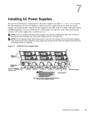
NOTE: If you must install the AC-cord retainer over all 6 AC power supplies slots. E1200i AC Power Supply Shelf Power Supplies On/Standby Switch AC-Cord Retainer Safety Cover AC-0 AC-1 AC-2 AC-3 AC-4 AC-5 AC-0 AC-3 AC-1 AC-4 AC-2 AC-5 WARNING - To comply with the..., they must be installed in place during normal operation. Locking Screw This retainer must be in the same row. NOTE: The On/Standby switch disconnects power to operate. 7 Installing AC Power Supplies The E1200 system requires a minimum of the chassis from all power cords. HIGH LEAKAGE ...
NOTE: If you must install the AC-cord retainer over all 6 AC power supplies slots. E1200i AC Power Supply Shelf Power Supplies On/Standby Switch AC-Cord Retainer Safety Cover AC-0 AC-1 AC-2 AC-3 AC-4 AC-5 AC-0 AC-3 AC-1 AC-4 AC-2 AC-5 WARNING - To comply with the..., they must be installed in place during normal operation. Locking Screw This retainer must be in the same row. NOTE: The On/Standby switch disconnects power to operate. 7 Installing AC Power Supplies The E1200 system requires a minimum of the chassis from all power cords. HIGH LEAKAGE ...

E1200i ExaScale Installation Guide
Page 31
... your power supplies and fan trays are secured to the building outlets by the qualified chassis installer or a qualified electrician. Verify that the On/Standby switch, located on either side of plug AC-0, is in the Standby (up) position (Figure 7-1). 2 Loosen the cord retainers locking screws (if needed) and tilt the...
... your power supplies and fan trays are secured to the building outlets by the qualified chassis installer or a qualified electrician. Verify that the On/Standby switch, located on either side of plug AC-0, is in the Standby (up) position (Figure 7-1). 2 Loosen the cord retainers locking screws (if needed) and tilt the...

E1200i ExaScale Installation Guide
Page 32
... power supplies and fan trays: Step Task 1 With the fan trays and power supplies installed, power on the system. • Flip the On/Standby switch located next to plug AC-0 to the OFF position. 6 Verify that the LEDs are properly installed. • Verify the remote power source. •... appropriate AC power supply in a manner that the system is booting. WARNING: Prevent exposure and contact with your local electrical codes. www.dell.com | support.dell.com • The AC-cord Retainer is complete. Do not attempt to operate this system without the AC-cord Retainer. • Your...
... power supplies and fan trays: Step Task 1 With the fan trays and power supplies installed, power on the system. • Flip the On/Standby switch located next to plug AC-0 to the OFF position. 6 Verify that the LEDs are properly installed. • Verify the remote power source. •... appropriate AC power supply in a manner that the system is booting. WARNING: Prevent exposure and contact with your local electrical codes. www.dell.com | support.dell.com • The AC-cord Retainer is complete. Do not attempt to operate this system without the AC-cord Retainer. • Your...

E1200i ExaScale Installation Guide
Page 33
Power Supply and Fan Tray LEDs Table 7-1. Blinking: GREEN Lit: YELLOW Blinking: YELLOW Lit: GREEN Unlit Installing AC Power Supplies | 33 Unlit: No connection Lit: GREEN Lit: AMBER LED is ... Fan Tray LEDs Status Booting Fault Detected Communication Failure Operational Loss of Power LED is ... Power Supply LEDs Status No AC power Operational (On/Standby switch may be set to Standby) Power Supply Failure Table 7-2.
Power Supply and Fan Tray LEDs Table 7-1. Blinking: GREEN Lit: YELLOW Blinking: YELLOW Lit: GREEN Unlit Installing AC Power Supplies | 33 Unlit: No connection Lit: GREEN Lit: AMBER LED is ... Fan Tray LEDs Status Booting Fault Detected Communication Failure Operational Loss of Power LED is ... Power Supply LEDs Status No AC power Operational (On/Standby switch may be set to Standby) Power Supply Failure Table 7-2.

E1200i ExaScale Installation Guide
Page 41
During boot, the blinking green LED may switch to blinking amber until the RPM boot is complete. • Check that the system is blinking amber after the system has booted, replace the fan ... is complete. blinking green fan tray LED indicates that the units are properly installed and are not lit. During boot, the blinking green LED may switch to the ON position. 2 Power Supply Status LEDs should be green. Installing DC Power Supplies | 41 If a fan tray is not operating properly or air...
During boot, the blinking green LED may switch to blinking amber until the RPM boot is complete. • Check that the system is blinking amber after the system has booted, replace the fan ... is complete. blinking green fan tray LED indicates that the units are properly installed and are not lit. During boot, the blinking green LED may switch to the ON position. 2 Power Supply Status LEDs should be green. Installing DC Power Supplies | 41 If a fan tray is not operating properly or air...

E1200i ExaScale Installation Guide
Page 43
...Line Card • Installing Line Cards and RPMs • Preparing and Installing RPMs and Line Cards • RPM Label and LEDs • Installing Switch Fabric Modules (SFM3s) • Line Card Cable Management Systems Unpacking an RPM or Line Card WARNING: Electrostatic discharge (ESD) damage can occur when... an ESD-preventive wrist or foot-heel ground strap when handling RPMs, SFM3s, or line cards. Installing RPMs, Line Cards, and SFM3s | 43 Force10 Networks recommends that you keep all components in a chassis. • When you are ready to install the cards, unwrap and install one card at...
...Line Card • Installing Line Cards and RPMs • Preparing and Installing RPMs and Line Cards • RPM Label and LEDs • Installing Switch Fabric Modules (SFM3s) • Line Card Cable Management Systems Unpacking an RPM or Line Card WARNING: Electrostatic discharge (ESD) damage can occur when... an ESD-preventive wrist or foot-heel ground strap when handling RPMs, SFM3s, or line cards. Installing RPMs, Line Cards, and SFM3s | 43 Force10 Networks recommends that you keep all components in a chassis. • When you are ready to install the cards, unwrap and install one card at...

E1200i ExaScale Installation Guide
Page 44
...alarms. Line Cards Your E1200 configuration requires a at least one line card. You can hot-insert a second RPM into a running with one Dell Force10 custom-built ASIC. The RPM Major and Minor alarm LEDs are controlled by the active RPM. A second RPM for redundancy. Line cards have ...one RPM, although two are recommended for an RPM in slot 0 first, Dell Force10 recommends you install your RPM in the E1200 chassis. The line card ports provide external interface functions for example, a router or switch). Do not force RPMs into line cards slots. The E1200 system requires ...
...alarms. Line Cards Your E1200 configuration requires a at least one line card. You can hot-insert a second RPM into a running with one Dell Force10 custom-built ASIC. The RPM Major and Minor alarm LEDs are controlled by the active RPM. A second RPM for redundancy. Line cards have ...one RPM, although two are recommended for an RPM in slot 0 first, Dell Force10 recommends you install your RPM in the E1200 chassis. The line card ports provide external interface functions for example, a router or switch). Do not force RPMs into line cards slots. The E1200 system requires ...

E1200i ExaScale Installation Guide
Page 47
... the card from the box. RPM Label and LEDs Table 9-1 describes the RPM LED states and the RPM front panel.RPMs control the routing and switching functions for the remaining cards and slots, in place by tightening the top and captive screws on its box and carefully remove the line card...
... the card from the box. RPM Label and LEDs Table 9-1 describes the RPM LED states and the RPM front panel.RPMs control the routing and switching functions for the remaining cards and slots, in place by tightening the top and captive screws on its box and carefully remove the line card...

E1200i ExaScale Installation Guide
Page 48
...required in use. Press the LT button to light. Green: flash memory card is turned on via the command line interface. www.dell.com | support.dell.com Table 9-1. Do not remove the flash card when the In Use LED is unlit. Nine SFM3s are able to temporarily illuminate ... for the E1200 system to verify that came with the card for triggering the different stages of alarms. Unlit: no minor alarm conditions. Installing Switch Fabric Modules (SFM3s) A minimum of -tolerance voltage. SFM3s plug directly into the backplane, which sets the threshold levels for to the routing ...
...required in use. Press the LT button to light. Green: flash memory card is turned on via the command line interface. www.dell.com | support.dell.com Table 9-1. Do not remove the flash card when the In Use LED is unlit. Nine SFM3s are able to temporarily illuminate ... for the E1200 system to verify that came with the card for triggering the different stages of alarms. Unlit: no minor alarm conditions. Installing Switch Fabric Modules (SFM3s) A minimum of -tolerance voltage. SFM3s plug directly into the backplane, which sets the threshold levels for to the routing ...

E1200i ExaScale Installation Guide
Page 55
... AC-Cord Retainer is installed on the remote power source is in the OFF position until you are filled. Verify that the switch on AC systems. • The power switch is in the OFF position for DC systems, and STANDBY for powering up your E1200 AC or DC system after you supply...
... AC-Cord Retainer is installed on the remote power source is in the OFF position until you are filled. Verify that the switch on AC systems. • The power switch is in the OFF position for DC systems, and STANDBY for powering up your E1200 AC or DC system after you supply...

E1200i ExaScale Installation Guide
Page 56
www.dell.com | support.dell.com Supplying Power - Supplying Power - If a power supply's LED is not lit or is amber:...If the fan tray LED remains unlit on power-up , replace the fan tray. AC Step Task 1 Flip the REMOTE power switch to the ON position. 4 The Status LED for each power supply should be green (online). Remove the card from the anti...-static bag. 3 Flip the On/Standby switch to the ON position. 2 Remove the card from the box. If a power supply's LED is not lit or is amber...
www.dell.com | support.dell.com Supplying Power - Supplying Power - If a power supply's LED is not lit or is amber:...If the fan tray LED remains unlit on power-up , replace the fan tray. AC Step Task 1 Flip the REMOTE power switch to the ON position. 4 The Status LED for each power supply should be green (online). Remove the card from the anti...-static bag. 3 Flip the On/Standby switch to the ON position. 2 Remove the card from the box. If a power supply's LED is not lit or is amber...

E1200i ExaScale Installation Guide
Page 60
...the AC cord is attached, power supply fans will spin, and the LEDs will indicate status while the On/ Standby switch is OFF. There are operating your E1200 AC chassis with only three Power Supplies (the minimum), you can install, ... Supply without removing the AC-cord retainer or the AC cords. 60 | Removing and Replacing Components NOTE: The On/Standby switch disconnects power to the rest of the chassis from all 6 AC power supplies. NOTE: If there is a Power Supply ... until the power supplied by the remote power source is in Standby. www.dell.com | support.dell.com Figure 12-1.
...the AC cord is attached, power supply fans will spin, and the LEDs will indicate status while the On/ Standby switch is OFF. There are operating your E1200 AC chassis with only three Power Supplies (the minimum), you can install, ... Supply without removing the AC-cord retainer or the AC cords. 60 | Removing and Replacing Components NOTE: The On/Standby switch disconnects power to the rest of the chassis from all 6 AC power supplies. NOTE: If there is a Power Supply ... until the power supplied by the remote power source is in Standby. www.dell.com | support.dell.com Figure 12-1.

E1200i ExaScale Installation Guide
Page 61
... in a non-redundant installation Step Task 1 Unplug the network interface cables connected to the line card or RPM. 2 Activate the disconnect switch at the Main power source or disconnect the AC cord at the remote power source. 3 Grip the handle and squeeze the thumb latch....lit), the entire Power Supply Module must be replaced. Remove an AC Power Supply in a redundant installation Step Task Power Supplies On/Standby Switch AC-Cord Retainer Safety Cover WARNING - HIGH LEAKAGE CURRENT. EARTH CONNECTION ESSENTIAL BEFORE CONNECTING SUPPLY. / / COURANT DE FUITE ELEVE. This ...
... in a non-redundant installation Step Task 1 Unplug the network interface cables connected to the line card or RPM. 2 Activate the disconnect switch at the Main power source or disconnect the AC cord at the remote power source. 3 Grip the handle and squeeze the thumb latch....lit), the entire Power Supply Module must be replaced. Remove an AC Power Supply in a redundant installation Step Task Power Supplies On/Standby Switch AC-Cord Retainer Safety Cover WARNING - HIGH LEAKAGE CURRENT. EARTH CONNECTION ESSENTIAL BEFORE CONNECTING SUPPLY. / / COURANT DE FUITE ELEVE. This ...

E1200i ExaScale Installation Guide
Page 62
Retaining screw Safety cover 3 Switch the Over Current Protector (located on the PEM front panel) to release the PEM 6 While holding the interlock lever up, using the bottom handle, pull ... E1200 with Bus bar 550-00061-01 Rev A 4 Loosen the Locking screws. 5 Lift and hold the PEM interlock lever to the OFF position. www.dell.com | support.dell.com Remove a DC Power Supply Step Task 1 Ensure that the remote power source is in the OFF position and that the PEM status light...
Retaining screw Safety cover 3 Switch the Over Current Protector (located on the PEM front panel) to release the PEM 6 While holding the interlock lever up, using the bottom handle, pull ... E1200 with Bus bar 550-00061-01 Rev A 4 Loosen the Locking screws. 5 Lift and hold the PEM interlock lever to the OFF position. www.dell.com | support.dell.com Remove a DC Power Supply Step Task 1 Ensure that the remote power source is in the OFF position and that the PEM status light...

E1200i ExaScale Installation Guide
Page 64
... a new SFM3 or reinsert an SFM3. * Remove the new SFM3 from the chassis. Avoid touching the printed circuit board and connector pins. www.dell.com | support.dell.com Step Task (continued) 5 If you are installing a line card, follow these procedures: • If you are hot-swapping (replacing the ... the backplane connections. NOTE: If you insert the card into the slot. System messages stating that the active interfaces' status changed and the switch fabric is up appear when an SFM3 is inserted correctly and traffic is interrupted. Wait 30 seconds until the cards are replaced. Slide the ...
... a new SFM3 or reinsert an SFM3. * Remove the new SFM3 from the chassis. Avoid touching the printed circuit board and connector pins. www.dell.com | support.dell.com Step Task (continued) 5 If you are installing a line card, follow these procedures: • If you are hot-swapping (replacing the ... the backplane connections. NOTE: If you insert the card into the slot. System messages stating that the active interfaces' status changed and the switch fabric is up appear when an SFM3 is inserted correctly and traffic is interrupted. Wait 30 seconds until the cards are replaced. Slide the ...

E1200i ExaScale Installation Guide
Page 86
...throughout the European Union. Users of EEE with California Code of life EEE as required by WEEE. Dell Force10 offers a variety of IT and Telecommunications Products Dell Force10 switches are labeled with the European WEEE Directive, electrical and electronic equipment (EEE) is provided in EEE. ...to responsibly recycle their IT products. Special handling may apply. www.dell.com | support.dell.com • EN 300 386 V1.3.3 (2005) EMC for Perchlorate Materials. 86 | System Specifications Dell Force10 encourages owners of used appliances as shown in recycling their equipment ...
...throughout the European Union. Users of EEE with California Code of life EEE as required by WEEE. Dell Force10 offers a variety of IT and Telecommunications Products Dell Force10 switches are labeled with the European WEEE Directive, electrical and electronic equipment (EEE) is provided in EEE. ...to responsibly recycle their IT products. Special handling may apply. www.dell.com | support.dell.com • EN 300 386 V1.3.3 (2005) EMC for Perchlorate Materials. 86 | System Specifications Dell Force10 encourages owners of used appliances as shown in recycling their equipment ...


