
Quick Start Guide
Page 7
... to both the C150 and C300 chassis. Lift the C150/300 chassis only from the bottom to install the chassis into the rack before installing the chassis. Avoid dropping the switch or its components. The following guidelines are mishandled. Install the chassis into a 19-inch equipment ...WARNING: Use an equipment lift or pallet jack when lifting or moving the chassis. NOTE: Unless stated otherwise, the installation instructions below . Installing the Chassis To install the C150/300 chassis, Dell Force10 recommends that the system remains stable. 1 Installing the Hardware This guide ...
... to both the C150 and C300 chassis. Lift the C150/300 chassis only from the bottom to install the chassis into the rack before installing the chassis. Avoid dropping the switch or its components. The following guidelines are mishandled. Install the chassis into a 19-inch equipment ...WARNING: Use an equipment lift or pallet jack when lifting or moving the chassis. NOTE: Unless stated otherwise, the installation instructions below . Installing the Chassis To install the C150/300 chassis, Dell Force10 recommends that the system remains stable. 1 Installing the Hardware This guide ...

Quick Start Guide
Page 12
...do not install more than the recommended maximum number of the chassis, leaving no blank slots between units. 4 Plug the AC power cord into the power receptacle in all unused PSU slots. Dell Force10 recommends installing power supplies starting from the left -most power ...switch is in the OFF (left) position. 2 Secure the retaining latch in either of the power supply. 5 Lower the retaining latch, and tighten it into place. 6 Plug the power cord into the top left side, top row of PSUs (given by the qualified chassis installer or a qualified electrician. WARNING: The C300...
...do not install more than the recommended maximum number of the chassis, leaving no blank slots between units. 4 Plug the AC power cord into the power receptacle in all unused PSU slots. Dell Force10 recommends installing power supplies starting from the left -most power ...switch is in the OFF (left) position. 2 Secure the retaining latch in either of the power supply. 5 Lower the retaining latch, and tighten it into place. 6 Plug the power cord into the top left side, top row of PSUs (given by the qualified chassis installer or a qualified electrician. WARNING: The C300...

Quick Start Guide
Page 13
C150 Entry Module Installation Over-Current Switch Safety Cover Handle Retaining Latch BLNK fn003lp fn003lp fn00012lpp BLNK BLNK BLNK Power Supply Blank C300 Power Entry Module Installation fn0002lp Installing the Hardware 11 Please contact the Dell Force10 TAC if you experience any difficulty during installation Step Task... blank (CC-CBLNK-PWR) on the PEM front panel) to the OFF position. 2 Turn the over-current switch (located on all empty slots with blank panels. CAUTION: Some CH-C300 chassis may require Dell Force10 assistance when using some DC power supplies.
C150 Entry Module Installation Over-Current Switch Safety Cover Handle Retaining Latch BLNK fn003lp fn003lp fn00012lpp BLNK BLNK BLNK Power Supply Blank C300 Power Entry Module Installation fn0002lp Installing the Hardware 11 Please contact the Dell Force10 TAC if you experience any difficulty during installation Step Task... blank (CC-CBLNK-PWR) on the PEM front panel) to the OFF position. 2 Turn the over-current switch (located on all empty slots with blank panels. CAUTION: Some CH-C300 chassis may require Dell Force10 assistance when using some DC power supplies.

Quick Start Guide
Page 19
... the unit, and replace the fan tray. If the fans are not lit green: • Check that the fan tray is not flowing through the chassis. You should be able to the system, the following should occur: • The fan tray should be operating. • The green (online) fan tray, ...17 When you supply power to hear the air flowing through the chassis: • Power off all power supplies. • Verify that the unit is operational. When the boot process is required at this point. On the C300, toggle the switch on self tests. RPM and line card LEDs blink as the system...
... the unit, and replace the fan tray. If the fans are not lit green: • Check that the fan tray is not flowing through the chassis. You should be able to the system, the following should occur: • The fan tray should be operating. • The green (online) fan tray, ...17 When you supply power to hear the air flowing through the chassis: • Power off all power supplies. • Verify that the unit is operational. When the boot process is required at this point. On the C300, toggle the switch on self tests. RPM and line card LEDs blink as the system...

Quick Start Guide
Page 26
... 1 Enable the interface. no shutdown 2 Place the interface in the prompt. Default Configuration A version of the Dell Force10 Operating System (FTOS) is pre-loaded onto the chassis, however the system is not configured when you power up for the first time (except for the default host ...name, which is force10. • Host names must configure the system using the Command Line Interface (CLI). Configure a Host Name The host name appears in switchport Layer 2 (switching) mode. The user cannot configure switching or Layer 2 protocols such as the spanning ...
... 1 Enable the interface. no shutdown 2 Place the interface in the prompt. Default Configuration A version of the Dell Force10 Operating System (FTOS) is pre-loaded onto the chassis, however the system is not configured when you power up for the first time (except for the default host ...name, which is force10. • Host names must configure the system using the Command Line Interface (CLI). Configure a Host Name The host name appears in switchport Layer 2 (switching) mode. The user cannot configure switching or Layer 2 protocols such as the spanning ...

C300 Hardware Installation Guide
Page 11
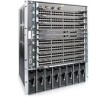
Figure 2-1. C300 Chassis (Front View) Front Mount Bracket 4-Port Fiber Line Card Fan Tray 0 1 2 3 R0 R1 4 SFM Status Master ACTIVE Alarm SFM Status Master ACTIVE Alarm RJ-45 ... Maintaining the C150 System 11 The 10-slot system contains two slots for Route Processor Modules (RPMs) and eight slots for line cards. 2 Overview The C300 is a high performance switch/router.
Figure 2-1. C300 Chassis (Front View) Front Mount Bracket 4-Port Fiber Line Card Fan Tray 0 1 2 3 R0 R1 4 SFM Status Master ACTIVE Alarm SFM Status Master ACTIVE Alarm RJ-45 ... Maintaining the C150 System 11 The 10-slot system contains two slots for Route Processor Modules (RPMs) and eight slots for line cards. 2 Overview The C300 is a high performance switch/router.

C300 Hardware Installation Guide
Page 12
... Connect console and management cables. 7 Install the power supplies. 8 Switch on page 39 12 | Overview Step Task 1 Prepare the site. 2 Unpack the chassis and components. 3 Install the chassis in the Manual Site Selection Criteria on page 13 Shipping and Storing ...power supplies. C300 Component Requirements Component Minimum Backplane (factory installed) 1 Fan tray 1 RPM 1 Line card 1 AC Power Supply 2 DC Power Entry Module 2 Maximum 1 1 2 8 8 8 Field-Replaceable No Yes Yes Yes Yes Yes C300 System Installation Process The Dell Force10 recommended installation...
... Connect console and management cables. 7 Install the power supplies. 8 Switch on page 39 12 | Overview Step Task 1 Prepare the site. 2 Unpack the chassis and components. 3 Install the chassis in the Manual Site Selection Criteria on page 13 Shipping and Storing ...power supplies. C300 Component Requirements Component Minimum Backplane (factory installed) 1 Fan tray 1 RPM 1 Line card 1 AC Power Supply 2 DC Power Entry Module 2 Maximum 1 1 2 8 8 8 Field-Replaceable No Yes Yes Yes Yes Yes C300 System Installation Process The Dell Force10 recommended installation...

C300 Hardware Installation Guide
Page 18
... the card has been inserted; these labels can occur when components are required in standby mode or is in use. Refer to chassis. NOTE: All chassis slots must be installed with the card for adequate system cooling, personal safety, and EMI containment during operation. Always wear an ESD...hot-swappable. Align the blank with the guides and gently slide toward the backplane. Always replace cards and blank panels immediately. Green: Switch Fabric is active Unlit: Switch Fabric is the Primary RPM. www.dell.com | support.dell.com Table 5-1. Indicates that card is lit.
... the card has been inserted; these labels can occur when components are required in standby mode or is in use. Refer to chassis. NOTE: All chassis slots must be installed with the card for adequate system cooling, personal safety, and EMI containment during operation. Always wear an ESD...hot-swappable. Align the blank with the guides and gently slide toward the backplane. Always replace cards and blank panels immediately. Green: Switch Fabric is active Unlit: Switch Fabric is the Primary RPM. www.dell.com | support.dell.com Table 5-1. Indicates that card is lit.

C300 Hardware Installation Guide
Page 29
...If there is beyond its limits. Power supplies are not field serviceable. AC Power Supply Handle l Switch O Power LED AC Power Receptacle Retaining Pin Threaded Hole Power Supply Retaining Pin fnC0002mp Each AC power...supply has one other unit operating in the chassis. Table 7-1. Power Supply Unit LED Description Status Off Flashing Green Solid Green Flashing Red Solid Red Description The unit is switched on but either unplugged or has low ...must be replaced. Do not supply power to your C300 system until the power supplies, blank panels, fan tray, RPMs, and line cards have been installed....
...If there is beyond its limits. Power supplies are not field serviceable. AC Power Supply Handle l Switch O Power LED AC Power Receptacle Retaining Pin Threaded Hole Power Supply Retaining Pin fnC0002mp Each AC power...supply has one other unit operating in the chassis. Table 7-1. Power Supply Unit LED Description Status Off Flashing Green Solid Green Flashing Red Solid Red Description The unit is switched on but either unplugged or has low ...must be replaced. Do not supply power to your C300 system until the power supplies, blank panels, fan tray, RPMs, and line cards have been installed....

C300 Hardware Installation Guide
Page 30
...PSU slots. Power Cord Requirements If using a power cord other then a Dell Force10 supplied power cord, the power source end of PSUs (given by the qualified chassis installer or a qualified electrician. www.dell.com | support.dell.com WARNING: Leakage Current (High Touch Current) in the OFF (bottom) ... causes high leakage current. To install an AC power supply: Step Task 1 Verify the switch is in AC-powered systems with local codes. WARNING: The C300 operates in either of the chassis, leaving no blank slots between units. The following are Dell Force10 supplied plug types.
...PSU slots. Power Cord Requirements If using a power cord other then a Dell Force10 supplied power cord, the power source end of PSUs (given by the qualified chassis installer or a qualified electrician. www.dell.com | support.dell.com WARNING: Leakage Current (High Touch Current) in the OFF (bottom) ... causes high leakage current. To install an AC power supply: Step Task 1 Verify the switch is in AC-powered systems with local codes. WARNING: The C300 operates in either of the chassis, leaving no blank slots between units. The following are Dell Force10 supplied plug types.

C300 Hardware Installation Guide
Page 37
... and contact with hazardous voltages. The PEM is labelled "1." For full redundancy, each PEM must be attached to the OFF position. 2 Turn off . Step Task 1 Switch the Over Current Protector (located on the PEM front panel) to a dedicated circuit breaker. The temperature is turned off the PEM. For example, PEM "0" connects... to circuit breaker "0" and PEM "1" connects to operate this system with a blank panels (CC-C-BLNK-PWR). Table 8-3. Removing a DC PEM The left chassis PEM slot is labelled "0" and the right...
... and contact with hazardous voltages. The PEM is labelled "1." For full redundancy, each PEM must be attached to the OFF position. 2 Turn off . Step Task 1 Switch the Over Current Protector (located on the PEM front panel) to a dedicated circuit breaker. The temperature is turned off the PEM. For example, PEM "0" connects... to circuit breaker "0" and PEM "1" connects to operate this system with a blank panels (CC-C-BLNK-PWR). Table 8-3. Removing a DC PEM The left chassis PEM slot is labelled "0" and the right...

C300 Hardware Installation Guide
Page 39
Supplying WARNING: Never operate the C300 System without a fan tray. Installing and Maintaining the C150 System 39 consider the nameplate rating of the unit. • Make sure the equipment is properly .... • All supply module is properly installed. • All supply modules are switched to the OFF (bottom) position. • The remote source complies with the input specifications in the section System Specifications on page 62. • Cables connect to the chassis, Dell Force10 recommends that : • The equipment rack or properly secured and grounded...
Supplying WARNING: Never operate the C300 System without a fan tray. Installing and Maintaining the C150 System 39 consider the nameplate rating of the unit. • Make sure the equipment is properly .... • All supply module is properly installed. • All supply modules are switched to the OFF (bottom) position. • The remote source complies with the input specifications in the section System Specifications on page 62. • Cables connect to the chassis, Dell Force10 recommends that : • The equipment rack or properly secured and grounded...

C300 Hardware Installation Guide
Page 40
www.dell.com | support.dell.com WARNING: The C300 operates in either of the supply. • Verify that the LEDs are unlit.... unlit, down the unit, and replace the fan tray. To turn off the AC supplies: • Toggle the switch two the OFF position. • Unplug the cord from the receptacle on the front of two voltage ranges. RPM ...50/60Hz 50/60Hz 6 primary + 2 redundant 3 primary + 1 redundant To supply the C300 system: Step 1 2 3 4 5 Task Verify that the unit is not flowing through the chassis. You should be lit and remain lit as long as the system is receiving and is required...
www.dell.com | support.dell.com WARNING: The C300 operates in either of the supply. • Verify that the LEDs are unlit.... unlit, down the unit, and replace the fan tray. To turn off the AC supplies: • Toggle the switch two the OFF position. • Unplug the cord from the receptacle on the front of two voltage ranges. RPM ...50/60Hz 50/60Hz 6 primary + 2 redundant 3 primary + 1 redundant To supply the C300 system: Step 1 2 3 4 5 Task Verify that the unit is not flowing through the chassis. You should be lit and remain lit as long as the system is receiving and is required...

C300 Hardware Installation Guide
Page 45
...source and the front of the power supply. 3 If using a DC PEM, turn the remote power source (the circuit breaker panel) and the over-current switch to the OFF position. 4 Pull the power supply out of the slot using a DC PEM, secure the ground connection and connect the -48 VDC and... a Line Card WARNING: Do not remove a panel blank unless you are required to the ON (top) position. 12 Turn up the chassis if necessary. You can add, replace, or remove C300 line cards without interrupting the system power or system operations. Blanks are ready to the line card. To remove and replace...
...source and the front of the power supply. 3 If using a DC PEM, turn the remote power source (the circuit breaker panel) and the over-current switch to the OFF position. 4 Pull the power supply out of the slot using a DC PEM, secure the ground connection and connect the -48 VDC and... a Line Card WARNING: Do not remove a panel blank unless you are required to the ON (top) position. 12 Turn up the chassis if necessary. You can add, replace, or remove C300 line cards without interrupting the system power or system operations. Blanks are ready to the line card. To remove and replace...

FTOS Command Line Reference Guide FTOS 8.4.2.7 E-Series TeraScale, C-Series, S-Series (S50/S25)
Page 26
...use all software features. 26 | CLI Basics The chassis mode is programmed into the CONFIGURATION mode. 2. You can switch to the INTERFACE mode by using the interface command or you can return to include (conf-router_isis). www.dell.com | support.dell.com ROUTER RIP Mode Use the ROUTER RIP mode... to configure RIP on the backplane of the chassis and the change takes place...
...use all software features. 26 | CLI Basics The chassis mode is programmed into the CONFIGURATION mode. 2. You can switch to the INTERFACE mode by using the interface command or you can return to include (conf-router_isis). www.dell.com | support.dell.com ROUTER RIP Mode Use the ROUTER RIP mode... to configure RIP on the backplane of the chassis and the change takes place...

FTOS Command Line Reference Guide FTOS 8.4.2.7 E-Series TeraScale, C-Series, S-Series (S50/S25)
Page 51
... E600i, E300, C300, C150) Control processor information and amount of memory. FTOS uptime is "/home/5.3.1/5.3.1.0/FTOS-ED-RPM1-5.3.1.0.bin" Chassis Type: E1200 Control Processor: IBM PowerPC 405GP (Rev D) with 268435456 bytes of non-volatile configuration memory. 1 Route Processor Module 9 Switch Fabric Module 1...that processor. Route Processor 1:... Build Time: Sun May 9 00:57:03 PT 2004 Build Path: /local/local0/Release/5-4-1/SW/Bsp/Diag Force10 uptime is 1 days, 3 hours, 16 minutes System image file is ... FTOS Operating... Route Processor 2:... File Management | 51 Command ...
... E600i, E300, C300, C150) Control processor information and amount of memory. FTOS uptime is "/home/5.3.1/5.3.1.0/FTOS-ED-RPM1-5.3.1.0.bin" Chassis Type: E1200 Control Processor: IBM PowerPC 405GP (Rev D) with 268435456 bytes of non-volatile configuration memory. 1 Route Processor Module 9 Switch Fabric Module 1...that processor. Route Processor 1:... Build Time: Sun May 9 00:57:03 PT 2004 Build Path: /local/local0/Release/5-4-1/SW/Bsp/Diag Force10 uptime is 1 days, 3 hours, 16 minutes System image file is ... FTOS Operating... Route Processor 2:... File Management | 51 Command ...

FTOS Command Line Reference Guide FTOS 8.4.2.7 E-Series TeraScale, C-Series, S-Series (S50/S25)
Page 150
....bin" Chassis Type: C300 Control Processor: IBM PowerPC 750FX (Rev D2.2) with 1073741824 bytes of memory. 128K bytes of non-volatile configuration memory. 1 Route Processor/Switch Fabric Module 2 48-port GE 10/100/1000Base-T line card with RJ45 interface (CB) 1 FastEthernet/IEEE 802.3 interface(s) 96 GigabitEthernet/IEEE 802.3 interface(s) show version Force10 Networks Real...
....bin" Chassis Type: C300 Control Processor: IBM PowerPC 750FX (Rev D2.2) with 1073741824 bytes of memory. 128K bytes of non-volatile configuration memory. 1 Route Processor/Switch Fabric Module 2 48-port GE 10/100/1000Base-T line card with RJ45 interface (CB) 1 FastEthernet/IEEE 802.3 interface(s) 96 GigabitEthernet/IEEE 802.3 interface(s) show version Force10 Networks Real...

FTOS Command Line Reference Guide FTOS 8.4.2.7 E-Series TeraScale, C-Series, S-Series (S50/S25)
Page 434
...acl Defaults None Command Modes EXEC Privilege Command History Version 7.8.1.0 Introduced on the chassis and all line cards. Information 434 | Content Addressable Memory (CAM) www.dell.com | support.dell.com Command History Version 8.4.1.0 Version 8.2.1.0 Version 7.9.1.0 Version 7.5.1.0 Version 7.4.2.0 ...Version 7.4.1.0 Version 6.5.1.0 Version 6.3.1.0 Added support for Layer 2 egress ACLs. Note: Do not use the ipv4-egacl-16 CAM profile for l2-switched-...
...acl Defaults None Command Modes EXEC Privilege Command History Version 7.8.1.0 Introduced on the chassis and all line cards. Information 434 | Content Addressable Memory (CAM) www.dell.com | support.dell.com Command History Version 8.4.1.0 Version 8.2.1.0 Version 7.9.1.0 Version 7.5.1.0 Version 7.4.2.0 ...Version 7.4.1.0 Version 6.5.1.0 Version 6.3.1.0 Added support for Layer 2 egress ACLs. Note: Do not use the ipv4-egacl-16 CAM profile for l2-switched-...

FTOS Command Line Reference Guide FTOS 8.4.2.7 E-Series TeraScale, C-Series, S-Series (S50/S25)
Page 437
... Syntax show cam-profile summary -- Command Output: show cam-profile summary FTOS#show cam-usage [acl | router | switch] Content Addressable Memory (CAM) | 437 Line card 6 -- CamSize Profile Name L2FIB L2ACL IPv4FIB IPv4ACL IPv4Flow EgL2ACL EgIPv4ACL... 0 entries : Default : Default -- Command Output: show cam-profile FTOS#show cam-usage e Display Layer 2, Layer 3, ACL, or all CAM usage statistics. Chassis CAM Profile -- : Current Settings : Next Boot Profile Name : Default : Default MicroCode Name : Default : Default : Current Settings : Next Boot -- Profile Name...
... Syntax show cam-profile summary -- Command Output: show cam-profile summary FTOS#show cam-usage [acl | router | switch] Content Addressable Memory (CAM) | 437 Line card 6 -- CamSize Profile Name L2FIB L2ACL IPv4FIB IPv4ACL IPv4Flow EgL2ACL EgIPv4ACL... 0 entries : Default : Default -- Command Output: show cam-profile FTOS#show cam-usage e Display Layer 2, Layer 3, ACL, or all CAM usage statistics. Chassis CAM Profile -- : Current Settings : Next Boot Profile Name : Default : Default MicroCode Name : Default : Default : Current Settings : Next Boot -- Profile Name...

FTOS Command Line Reference Guide FTOS 8.4.2.7 E-Series TeraScale, C-Series, S-Series (S50/S25)
Page 538
...possible for major releases and lower, while a hitless upgrade can also be used to upgrade the software on an E-Series chassis only) to provide a hitless or warm upgrade. All linecards will be done by the SFM slot number. Example Figure ...dell.com Command History Version 8.3.1.0 Version 8.1.1.0 Version 7.6.1.0 Added the all option Introduced on E-Series ExaScale Introduced on E-Series Usage Information Enabling this command will keep the failed RPM in the following example: Note: On C-Series, this command could affect traffic (even during hot-failover) since the switch...
...possible for major releases and lower, while a hitless upgrade can also be used to upgrade the software on an E-Series chassis only) to provide a hitless or warm upgrade. All linecards will be done by the SFM slot number. Example Figure ...dell.com Command History Version 8.3.1.0 Version 8.1.1.0 Version 7.6.1.0 Added the all option Introduced on E-Series ExaScale Introduced on E-Series Usage Information Enabling this command will keep the failed RPM in the following example: Note: On C-Series, this command could affect traffic (even during hot-failover) since the switch...


