Owner's Manual
Page 4
... designed for an earlier Microsoft® Windows® operating system 39 A solid blue screen appears 39 Other software problems 39 Media Card Reader Problems 40 Memory Problems 41 Mouse Problems 41 Network Problems 42 4 Contents
... designed for an earlier Microsoft® Windows® operating system 39 A solid blue screen appears 39 Other software problems 39 Media Card Reader Problems 40 Memory Problems 41 Mouse Problems 41 Network Problems 42 4 Contents
Owner's Manual
Page 6
Memory 66 Memory Installation Guidelines 66 Addressing Memory With 4-GB Configurations 67 Installing Memory 68 Removing Memory 69 Cards 70 PCI Cards 70 PCI Express Cards 76 Drive Panel 81 Removing the Drive Panel 81 Removing the Drive-Panel Insert 83 Replacing ...
Memory 66 Memory Installation Guidelines 66 Addressing Memory With 4-GB Configurations 67 Installing Memory 68 Removing Memory 69 Cards 70 PCI Cards 70 PCI Express Cards 76 Drive Panel 81 Removing the Drive Panel 81 Removing the Drive-Panel Insert 83 Replacing ...
Owner's Manual
Page 10
..., service contract, online discussions with other Dell customers NOTE: Select your region to support.dell.com and click Downloads. 2 Enter your Service Tag or product model. 3 In the Download Category drop-down menu, click All. 4 Select the operating system and operating system language for components, such as memory, the hard drive, and the...
..., service contract, online discussions with other Dell customers NOTE: Select your region to support.dell.com and click Downloads. 2 Enter your Service Tag or product model. 3 In the Download Category drop-down menu, click All. 4 Select the operating system and operating system language for components, such as memory, the hard drive, and the...
Owner's Manual
Page 19
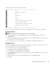
... the Volume Control window. Adjusting the Volume NOTE: When the speakers are muted, you that the current resolution and color depth are using too much memory and preventing DVD playback, adjust the display properties: 1 Click the Start button and click Control Panel. 2 Under Pick a category, click Appearance and Themes. 3 Under Pick...
... the Volume Control window. Adjusting the Volume NOTE: When the speakers are muted, you that the current resolution and color depth are using too much memory and preventing DVD playback, adjust the display properties: 1 Click the Start button and click Control Panel. 2 Under Pick a category, click Appearance and Themes. 3 Under Pick...
Owner's Manual
Page 22
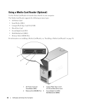
...• SmartMedia (SMC) • CompactFlash Type I and II (CF I/II) • MicroDrive Card • SecureDigital Card (SD) • MultiMediaCard (MMC) • Memory Stick (MS/MS Pro) For information on installing a Media Card Reader, see "Installing a Media Card Reader" on page 98. 1 2 3 4 1 xD-Picture Card ...and 2 SmartMedia (SMC) 3 Memory Stick (MS/MS Pro) 4 CompactFlash Type I and II (CF I/II) and MicroDrive Card SecureDigital Card (SD)/ MultiMediaCard (MMC) 22 Setting Up and Using...
...• SmartMedia (SMC) • CompactFlash Type I and II (CF I/II) • MicroDrive Card • SecureDigital Card (SD) • MultiMediaCard (MMC) • Memory Stick (MS/MS Pro) For information on installing a Media Card Reader, see "Installing a Media Card Reader" on page 98. 1 2 3 4 1 xD-Picture Card ...and 2 SmartMedia (SMC) 3 Memory Stick (MS/MS Pro) 4 CompactFlash Type I and II (CF I/II) and MicroDrive Card SecureDigital Card (SD)/ MultiMediaCard (MMC) 22 Setting Up and Using...

Owner's Manual
Page 27
... hard drive and then completely turning off the hard drive. The Power schemes drop-down menu. If you want to select one of the computer memory, Dell creates an appropriately sized hibernate mode file before it was in hibernate mode. To activate hibernate mode: 1 Click the Start button and click Control Panel...
... hard drive and then completely turning off the hard drive. The Power schemes drop-down menu. If you want to select one of the computer memory, Dell creates an appropriately sized hibernate mode file before it was in hibernate mode. To activate hibernate mode: 1 Click the Start button and click Control Panel...
Owner's Manual
Page 41
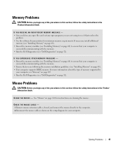
... the mouse directly to ensure that your computer, see "Memory" on page 107. • Run the Dell Diagnostics (see "Dell Diagnostics" on page 52). For more information about the type of memory supported by your computer is successfully communicating with the memory. • Run the Dell Diagnostics (see "Dell Diagnostics" on page 52). Mouse Problems CAUTION: Before...
... the mouse directly to ensure that your computer, see "Memory" on page 107. • Run the Dell Diagnostics (see "Dell Diagnostics" on page 52). For more information about the type of memory supported by your computer is successfully communicating with the memory. • Run the Dell Diagnostics (see "Dell Diagnostics" on page 52). Mouse Problems CAUTION: Before...

Owner's Manual
Page 43
...; Ensure that the network is securely connected to the system board (see "System Board Components" on page 65). • Remove and then reinstall the memory modules (see "Installing Memory" on . I F T H E P O W E R L I G H T I S B L I N K I N G G R E E N - See "Diagnostic Lights" on page 55. Contact your network administrator or the person who set up your network to verify that your...
...; Ensure that the network is securely connected to the system board (see "System Board Components" on page 65). • Remove and then reinstall the memory modules (see "Installing Memory" on . I F T H E P O W E R L I G H T I S B L I N K I N G G R E E N - See "Diagnostic Lights" on page 55. Contact your network administrator or the person who set up your network to verify that your...
Owner's Manual
Page 49
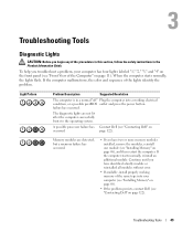
... page 68), and then restart the computer. To help you troubleshoot a problem, your computer (see "Installing Memory" on page 68). • If the problem persists, contact Dell (see "Front View of the procedures in this section, follow the safety instructions in a normal "off" Plug the ... the front panel (see "Contacting Dell" on page 122). If the computer starts normally, reinstall an additional module. Troubleshooting Tools Diagnostic Lights CAUTION: Before you begin any of the Computer" on page 11). Memory modules are not lit after the computer successfully boots to the operating...
... page 68), and then restart the computer. To help you troubleshoot a problem, your computer (see "Installing Memory" on page 68). • If the problem persists, contact Dell (see "Front View of the procedures in this section, follow the safety instructions in a normal "off" Plug the ... the front panel (see "Contacting Dell" on page 122). If the computer starts normally, reinstall an additional module. Troubleshooting Tools Diagnostic Lights CAUTION: Before you begin any of the Computer" on page 11). Memory modules are not lit after the computer successfully boots to the operating...

Owner's Manual
Page 50
... install a graphics card that you are installing are compatible with your computer (see "Memory Installation Guidelines" on page 66). • If the problem persists, contact Dell (see "Contacting Dell" on page 122). 50 Troubleshooting Tools Reseat all USB devices, check cable connections, and... know works and restart the computer. • If the problem persists or the computer has integrated graphics, contact Dell (see "Installing Memory" on page 122). Memory modules are detected. Continue until you have identified a faulty module or reinstalled all modules without error. • ...
... install a graphics card that you are installing are compatible with your computer (see "Memory Installation Guidelines" on page 66). • If the problem persists, contact Dell (see "Contacting Dell" on page 122). 50 Troubleshooting Tools Reseat all USB devices, check cable connections, and... know works and restart the computer. • If the problem persists or the computer has integrated graphics, contact Dell (see "Installing Memory" on page 122). Memory modules are detected. Continue until you have identified a faulty module or reinstalled all modules without error. • ...

Owner's Manual
Page 53
.... Displays your Microsoft® Windows® operating system. Allows you with required drivers already installed-no further installation or configuration is needed. Dell ships your computer to you to customize the test by changing the test settings. 4 Close the test screen to return to the Main Menu... You may need to your operating system • Connect or install a new device Identifying Drivers If you run a test from system setup, memory, and various internal tests, and it displays the information in the device list in the following table for running the test. Drivers What Is a...
.... Displays your Microsoft® Windows® operating system. Allows you with required drivers already installed-no further installation or configuration is needed. Dell ships your computer to you to customize the test by changing the test settings. 4 Close the test screen to return to the Main Menu... You may need to your operating system • Connect or install a new device Identifying Drivers If you run a test from system setup, memory, and various internal tests, and it displays the information in the device list in the following table for running the test. Drivers What Is a...
Owner's Manual
Page 65
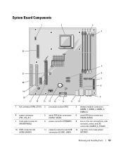
... (PW_12V_A1) 7 front-panel connector (FRONTPANEL) 10 USB connectors (2) (USB2_BACK1) 5 serial ATA drive connectors (SATA2, SATA3) 8 power connector (POWER1) 11 network connector and USB connectors (2) (NIC_USB1) 3 memory module connectors (DIMM_1, DIMM_2, DIMM_3, DIMM_4) 6 serial ATA drive connectors (SATA0, SATA1) 9 line-in, line-out, microphone, side surround, center, and LFE connectors (AUDIO_6_STACK) 12...
... (PW_12V_A1) 7 front-panel connector (FRONTPANEL) 10 USB connectors (2) (USB2_BACK1) 5 serial ATA drive connectors (SATA2, SATA3) 8 power connector (POWER1) 11 network connector and USB connectors (2) (NIC_USB1) 3 memory module connectors (DIMM_1, DIMM_2, DIMM_3, DIMM_4) 6 serial ATA drive connectors (SATA0, SATA1) 9 line-in, line-out, microphone, side surround, center, and LFE connectors (AUDIO_6_STACK) 12...
Owner's Manual
Page 66
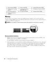
... modules function at the slowest speed installed. 66 Removing and Installing Parts NOTICE: Do not install ECC or buffered memory modules. If the memory modules are not installed in matched pairs, the computer will operate, but with connectors DIMM_1 and DIMM_2, then connectors DIMM_3 ...PCI connector (SLOT4) 15 Internal USB connector (USB1) 18 PCI Express x1 connector (SLOT2) 21 password jumper (PSWD) Memory You can increase your computer memory by your computer, see "Memory" on the module to determine the module's capacity.) For example, if you must be installed in pairs of matched...
... modules function at the slowest speed installed. 66 Removing and Installing Parts NOTICE: Do not install ECC or buffered memory modules. If the memory modules are not installed in matched pairs, the computer will operate, but with connectors DIMM_1 and DIMM_2, then connectors DIMM_3 ...PCI connector (SLOT4) 15 Internal USB connector (USB1) 18 PCI Express x1 connector (SLOT2) 21 password jumper (PSWD) Memory You can increase your computer memory by your computer, see "Memory" on the module to determine the module's capacity.) For example, if you must be installed in pairs of matched...

Owner's Manual
Page 67
... or DIMM connectors 3 and 4. Any address space reserved for these components cannot be used by computer memory. You should install your original memory modules in pairs either in the 4-GB range. NOTE: Memory purchased from Dell. Otherwise, your computer may have, even if you purchased the new modules from... Dell is less than that you may not start properly. Removing and Installing Parts 67 however, the amount of memory available to the operating system is...
... or DIMM connectors 3 and 4. Any address space reserved for these components cannot be used by computer memory. You should install your original memory modules in pairs either in the 4-GB range. NOTE: Memory purchased from Dell. Otherwise, your computer may have, even if you purchased the new modules from... Dell is less than that you may not start properly. Removing and Installing Parts 67 however, the amount of memory available to the operating system is...
Owner's Manual
Page 68
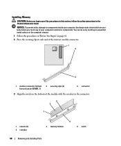
...any of the procedures in this section, follow the safety instructions in the connector. 3 2 1 1 cutouts (2) 4 crossbar 4 2 memory module 3 notch 68 Removing and Installing Parts NOTICE: To prevent static damage to components inside your computer, discharge static electricity from processor (...securing clips (2) 3 connector 3 Align the notch on page 61. 2 Press the securing clip at each end of the memory module connector. 1 2 3 1 memory connector farthest from your computer's electronic components. You can do so by touching an unpainted metal surface on the computer chassis....
...any of the procedures in this section, follow the safety instructions in the connector. 3 2 1 1 cutouts (2) 4 crossbar 4 2 memory module 3 notch 68 Removing and Installing Parts NOTICE: To prevent static damage to components inside your computer, discharge static electricity from processor (...securing clips (2) 3 connector 3 Align the notch on page 61. 2 Press the securing clip at each end of the memory module connector. 1 2 3 1 memory connector farthest from your computer's electronic components. You can do so by touching an unpainted metal surface on the computer chassis....

Owner's Manual
Page 69
... so by touching an unpainted metal surface on the computer chassis. 1 Follow the procedures in the Product Information Guide. NOTICE: To avoid damage to the memory module, press the module straight down into the connector while you apply equal force to each end of the module. 4 Insert the module into the... turn them on page 61. 2 Press out the securing clip at the end of the board and lift up. Removing and Installing Parts 69 Removing Memory CAUTION: Before you touch any of the procedures in this section, follow the safety instructions in "Before You Begin" on . 7 Right-click the My ...
... so by touching an unpainted metal surface on the computer chassis. 1 Follow the procedures in the Product Information Guide. NOTICE: To avoid damage to the memory module, press the module straight down into the connector while you apply equal force to each end of the module. 4 Insert the module into the... turn them on page 61. 2 Press out the securing clip at the end of the board and lift up. Removing and Installing Parts 69 Removing Memory CAUTION: Before you touch any of the procedures in this section, follow the safety instructions in "Before You Begin" on . 7 Right-click the My ...

Owner's Manual
Page 107
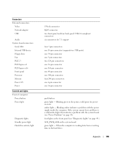
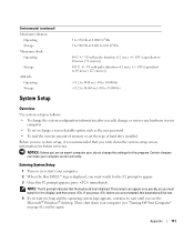
Appendix Specifications Processor Processor type Level 2 (L2) cache Memory Type Memory connectors Memory capacities Minimum memory Maximum memory Computer Information Chipset RAID Support DMA channels Interrupt levels BIOS chip (NVRAM) NIC Video Type AMD Athlon 64 X2 dual-core processor AMD ...MHz, 667-MHz, 800-MHz (when available) DDR2 SDRAM four 256 MB, 512 MB, or 1 GB non-ECC 256 MB 4 GB NOTE: See "Addressing Memory With 4-GB Configurations" on page 67 to verify the amount of 10/100 communication Nvidia integrated video (DirectX 9.0 Shader Model 3.0 Graphics Processing Unit) or optional...
Appendix Specifications Processor Processor type Level 2 (L2) cache Memory Type Memory connectors Memory capacities Minimum memory Maximum memory Computer Information Chipset RAID Support DMA channels Interrupt levels BIOS chip (NVRAM) NIC Video Type AMD Athlon 64 X2 dual-core processor AMD ...MHz, 667-MHz, 800-MHz (when available) DDR2 SDRAM four 256 MB, 512 MB, or 1 GB non-ECC 256 MB 4 GB NOTE: See "Addressing Memory With 4-GB Configurations" on page 67 to verify the amount of 10/100 communication Nvidia integrated video (DirectX 9.0 Shader Model 3.0 Graphics Processing Unit) or optional...

Owner's Manual
Page 108
... lanes Drives Externally accessible: Bays Available devices Internally accessible: one 3.5-inch drive bay (FlexBay) two 5.25-inch drive bays Serial ATA drives (4), floppy drive, USB memory devices, CD/DVD drive, and Media Card Reader two bays for 1-inch high serial ATA hard drives 108 Appendix
... lanes Drives Externally accessible: Bays Available devices Internally accessible: one 3.5-inch drive bay (FlexBay) two 5.25-inch drive bays Serial ATA drives (4), floppy drive, USB memory devices, CD/DVD drive, and Media Card Reader two bays for 1-inch high serial ATA hard drives 108 Appendix
Owner's Manual
Page 109
... Network adapter USB Audio System board connectors: Serial ATA Internal USB device Floppy drive Fan PCI 2.3 PCI Express x1 PCI Express x16 Front panel Processor Memory Power 12V Power Controls and Lights Front of computer: Power button Power light Diagnostic lights Standby power light Hard-drive activity light 15-hole connector...
... Network adapter USB Audio System board connectors: Serial ATA Internal USB device Floppy drive Fan PCI 2.3 PCI Express x1 PCI Express x16 Front panel Processor Memory Power 12V Power Controls and Lights Front of computer: Power button Power light Diagnostic lights Standby power light Hard-drive activity light 15-hole connector...
Owner's Manual
Page 111
...the operating system logo appears, continue to wait until you see "Turning Off Your Computer" on (or restart) your computer. 2 When the blue DELL™ logo is recommended that the keyboard has initialized. NOTICE: Unless you are prompted, this program. If you press before you are an expert ...8226; To change the system configuration information after you add, change, or remove any hardware in your computer • To set the type of memory or set or change the settings for future reference. Certain changes can appear very quickly, so you must watch for it is displayed, you ...
...the operating system logo appears, continue to wait until you see "Turning Off Your Computer" on (or restart) your computer. 2 When the blue DELL™ logo is recommended that the keyboard has initialized. NOTICE: Unless you are prompted, this program. If you press before you are an expert ...8226; To change the system configuration information after you add, change, or remove any hardware in your computer • To set the type of memory or set or change the settings for future reference. Certain changes can appear very quickly, so you must watch for it is displayed, you ...


