Owner's Manual
Page 1
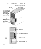
Dell™ Dimension™ 5150/E510 Owner's Manual Service Tag cover latch release CD or DVD eject button CD or DVD activity light FlexBay for optional floppy drive or Media Card Reader microphone connector headphone connector diagnostic lights hard-drive activity light power button/ power activity light USB 2.0 connectors (2) power connector sound connectors (integrated) (5) VGA video connector (integrated) network adapter USB 2.0 connectors (5) Model DCSM card slots for PCI Express x16 (1), PCI (2), PCI Express x1 (1) www.dell.com | support.dell.com
Dell™ Dimension™ 5150/E510 Owner's Manual Service Tag cover latch release CD or DVD eject button CD or DVD activity light FlexBay for optional floppy drive or Media Card Reader microphone connector headphone connector diagnostic lights hard-drive activity light power button/ power activity light USB 2.0 connectors (2) power connector sound connectors (integrated) (5) VGA video connector (integrated) network adapter USB 2.0 connectors (5) Model DCSM card slots for PCI Express x16 (1), PCI (2), PCI Express x1 (1) www.dell.com | support.dell.com

Owner's Manual
Page 3
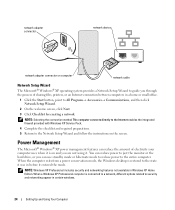
... 22 Connecting a TV 23 Changing the Display Settings 23 Setting Up a Home and Office Network 23 Connecting to a Network Adapter 23 Network Setup Wizard 24 Power Management 24 Standby Mode 25 Hibernate Mode 25 Power Options Properties 25 Hyper-Threading 27 Contents 3
... 22 Connecting a TV 23 Changing the Display Settings 23 Setting Up a Home and Office Network 23 Connecting to a Network Adapter 23 Network Setup Wizard 24 Power Management 24 Standby Mode 25 Hibernate Mode 25 Power Options Properties 25 Hyper-Threading 27 Contents 3
Owner's Manual
Page 4
... Microsoft® Windows® operating system 37 A solid blue screen appears 37 Other software problems 38 Memory Problems 38 Mouse Problems 39 Network Problems 40 Power Problems 40 4 Contents
... Microsoft® Windows® operating system 37 A solid blue screen appears 37 Other software problems 38 Memory Problems 38 Mouse Problems 39 Network Problems 40 Power Problems 40 4 Contents
Owner's Manual
Page 6
... Replacing the Drive-Panel Insert 82 Replacing the Drive Panel 82 Drives 83 IDE Drive Addressing 83 Connecting Drive Cables 84 Drive Interface Connectors 84 Power Cable Connector 84 Connecting and Disconnecting Drive Cables 85 Hard Drive 85 Removing a Hard Drive 85 Installing a Hard Drive 86 Adding a Second Hard Drive 88...
... Replacing the Drive-Panel Insert 82 Replacing the Drive Panel 82 Drives 83 IDE Drive Addressing 83 Connecting Drive Cables 84 Drive Interface Connectors 84 Power Cable Connector 84 Connecting and Disconnecting Drive Cables 85 Hard Drive 85 Removing a Hard Drive 85 Installing a Hard Drive 86 Adding a Second Hard Drive 88...
Owner's Manual
Page 24
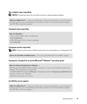
... on and you are not using it entered the mode. When the computer exits from a power conservation mode, the Windows desktop is restored to the state it was in before it . Power Management The Microsoft® Windows® XP power management features can use standby mode or hibernate mode to reduce... power to the entire computer. You can reduce power to just the monitor or the hard drive, or you can reduce...
... on and you are not using it entered the mode. When the computer exits from a power conservation mode, the Windows desktop is restored to the state it was in before it . Power Management The Microsoft® Windows® XP power management features can use standby mode or hibernate mode to reduce... power to the entire computer. You can reduce power to just the monitor or the hard drive, or you can reduce...
Owner's Manual
Page 25
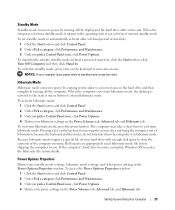
.... Hibernate Mode Hibernate mode conserves power by . Because hibernate mode requires a special file on your hibernate settings on the keyboard or moving the mouse does not bring the computer out of the computer memory, Dell creates an appropriately sized hibernate mode file before shipping the computer... to the state it was in the Power Options Properties window. If the computer's hard drive becomes corrupted, Windows XP ...
.... Hibernate Mode Hibernate mode conserves power by . Because hibernate mode requires a special file on your hibernate settings on the keyboard or moving the mouse does not bring the computer out of the computer memory, Dell creates an appropriately sized hibernate mode file before shipping the computer... to the state it was in the Power Options Properties window. If the computer's hard drive becomes corrupted, Windows XP ...
Owner's Manual
Page 26
... turning off the computer. Changing the time-out for a scheme field permanently changes the default settings for that scheme, unless you require minimal power conservation. • Presentation - To program these functions, click an option from the corresponding drop-down menu displays the following schemes: •...be locked up. If you to activate standby mode, activate hibernate mode, or turn off the hard drive. For more information on power management options: 1 Click the Start button and click Help and Support. 2 In the Help and Support window, click Performance and maintenance...
... turning off the computer. Changing the time-out for a scheme field permanently changes the default settings for that scheme, unless you require minimal power conservation. • Presentation - To program these functions, click an option from the corresponding drop-down menu displays the following schemes: •...be locked up. If you to activate standby mode, activate hibernate mode, or turn off the hard drive. For more information on power management options: 1 Click the Start button and click Help and Support. 2 In the Help and Support window, click Performance and maintenance...
Owner's Manual
Page 36
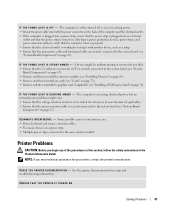
... KEYBOARD CABLE - • Ensure that appears only when the FlexBay device is installed. See "Resolving Software and Hardware Incompatibilities" on page 47. ENSURE THAT THE POWER CABLE IS FIRMLY CONNECTED TO THE COMPUTER AND TO THE ELECTRICAL OUTLET. 36 Solving Problems If the FlexBay device is physically installed, but it is...
... KEYBOARD CABLE - • Ensure that appears only when the FlexBay device is installed. See "Resolving Software and Hardware Incompatibilities" on page 47. ENSURE THAT THE POWER CABLE IS FIRMLY CONNECTED TO THE COMPUTER AND TO THE ELECTRICAL OUTLET. 36 Solving Problems If the FlexBay device is physically installed, but it is...
Owner's Manual
Page 37
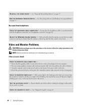
... You might lose data if you are unable to get a response by pressing a key on your keyboard or moving your mouse, press and hold the power button for at least 8 to 10 seconds until the computer turns off . If you are unable to get a response by pressing a key on your... keyboard or moving your mouse, press and hold the power button for at least 8 to 10 seconds until the computer turns off . A program crashes repeatedly NOTE: Software usually includes installation instructions in an environment ...
... You might lose data if you are unable to get a response by pressing a key on your keyboard or moving your mouse, press and hold the power button for at least 8 to 10 seconds until the computer turns off . If you are unable to get a response by pressing a key on your... keyboard or moving your mouse, press and hold the power button for at least 8 to 10 seconds until the computer turns off . A program crashes repeatedly NOTE: Software usually includes installation instructions in an environment ...

Owner's Manual
Page 40
... U B L E S H O O T E R - Press a key on page 106. For a description of network lights, see "Controls and Lights" on the keyboard, move the mouse, or press the power button to verify that your network to resume normal operation. 40 Solving Problems Ensure that the network cable is off, that the network is in... the Product Information Guide. C H E C K T H E N E T W O R K C A B L E C O N N E C T O R - Replace the network cable. Power Problems CAUTION: Before you begin any of the procedures in this section, follow the safety instructions in the Product Information Guide.
... U B L E S H O O T E R - Press a key on page 106. For a description of network lights, see "Controls and Lights" on the keyboard, move the mouse, or press the power button to verify that your network to resume normal operation. 40 Solving Problems Ensure that the network cable is off, that the network is in... the Product Information Guide. C H E C K T H E N E T W O R K C A B L E C O N N E C T O R - Replace the network cable. Power Problems CAUTION: Before you begin any of the procedures in this section, follow the safety instructions in the Product Information Guide.
Owner's Manual
Page 41
... extension cables • Too many devices on page 76). See the printer documentation for your location (if applicable). • Ensure that the power strip is plugged into both the power connector on page 67). Some possible causes of interference are securely connected to the system board (see "System Board Components" on page...
... extension cables • Too many devices on page 76). See the printer documentation for your location (if applicable). • Ensure that the power strip is plugged into both the power connector on page 67). Some possible causes of interference are securely connected to the system board (see "System Board Components" on page...
Owner's Manual
Page 44
... - • Ensure that the headphone cable is blinking, press a key on page 47. 44 Solving Problems If the power light is securely inserted into the headphone connector (see "headphone connector" on page 61). See "Diagnostic Lights" on the keyboard... or move the mouse. Ensure that the graphics cable is working by testing it with another device, such as shown on . If the power light is off, firmly press the button to have missing pins.) C H E C K T H E M O N I T O R P O W E R L I O N - R U N T H E H A R D W A R E TR O U B L E S H O O T E R - See "Resolving ...
... - • Ensure that the headphone cable is blinking, press a key on page 47. 44 Solving Problems If the power light is securely inserted into the headphone connector (see "headphone connector" on page 61). See "Diagnostic Lights" on the keyboard... or move the mouse. Ensure that the graphics cable is working by testing it with another device, such as shown on . If the power light is off, firmly press the button to have missing pins.) C H E C K T H E M O N I T O R P O W E R L I O N - R U N T H E H A R D W A R E TR O U B L E S H O O T E R - See "Resolving ...
Owner's Manual
Page 47
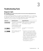
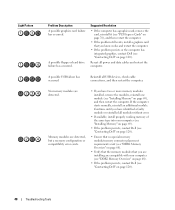
... "Contacting Dell" on page 120). After the computer starts, all modules without error. • If available, install properly working memory of the same type into a working electrical condition or a possible pre-BIOS outlet and press the power button. "Power Problems" on occurred.... Light Pattern Problem Description Suggested Resolution The computer is in the Product Information Guide. A possible processor failure has Contact Dell (see failure has occurred. If the computer malfunctions, the color and sequence of the Computer" on page 63). Troubleshooting...
... "Contacting Dell" on page 120). After the computer starts, all modules without error. • If available, install properly working memory of the same type into a working electrical condition or a possible pre-BIOS outlet and press the power button. "Power Problems" on occurred.... Light Pattern Problem Description Suggested Resolution The computer is in the Product Information Guide. A possible processor failure has Contact Dell (see failure has occurred. If the computer malfunctions, the color and sequence of the Computer" on page 63). Troubleshooting...
Owner's Manual
Page 48
...you have two or more memory modules installed, remove the modules, reinstall one module (see "Contacting Dell" on page 69), and then restart the computer. Reinstall all power and data cables and restart the computer. Memory modules are detected, but a memory configuration or compatibility...No memory modules are compatible with your computer (see "Installing Memory" on page 69). • If the problem persists, contact Dell (see "Contacting Dell" on page 120). • Ensure that no special memory module/memory connector placement requirements exist (see "DDR2 Memory Overview" on...
...you have two or more memory modules installed, remove the modules, reinstall one module (see "Contacting Dell" on page 69), and then restart the computer. Reinstall all power and data cables and restart the computer. Memory modules are detected, but a memory configuration or compatibility...No memory modules are compatible with your computer (see "Installing Memory" on page 69). • If the problem persists, contact Dell (see "Contacting Dell" on page 120). • Ensure that no special memory module/memory connector placement requirements exist (see "DDR2 Memory Overview" on...
Owner's Manual
Page 59
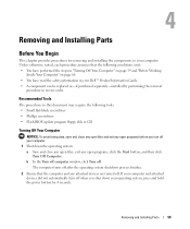
...and Installing Parts Before You Begin This chapter provides procedures for removing and installing the components in your operating system, press and hold the power button for 4 seconds. If your computer and attached devices did not automatically turn off when you shut down the operating system: a...and exit any open files, exit any attached devices are turned off. b In the Turn off computer window, click Turn off your Dell™ Product Information Guide. • A component can be replaced or-if purchased separately-installed by performing the removal procedure in this document...
...and Installing Parts Before You Begin This chapter provides procedures for removing and installing the components in your operating system, press and hold the power button for 4 seconds. If your computer and attached devices did not automatically turn off when you shut down the operating system: a...and exit any open files, exit any attached devices are turned off. b In the Turn off computer window, click Turn off your Dell™ Product Information Guide. • A component can be replaced or-if purchased separately-installed by performing the removal procedure in this document...
Owner's Manual
Page 60
... in on page 65). if you are correctly oriented and aligned. Also, before you connect a cable, ensure that is not authorized by Dell is not covered by touching an unpainted metal surface, such as a processor by its edges, not by its metal mounting bracket. NOTICE: ...to ground the system board. CAUTION: To guard against electrical shock, always unplug your computer from their electrical outlets, and then press the power button to help ensure your computer from the network device. 2 Disconnect any static electricity that could harm internal components. 60 Removing and ...
... in on page 65). if you are correctly oriented and aligned. Also, before you connect a cable, ensure that is not authorized by Dell is not covered by touching an unpainted metal surface, such as a processor by its edges, not by its metal mounting bracket. NOTICE: ...to ground the system board. CAUTION: To guard against electrical shock, always unplug your computer from their electrical outlets, and then press the power button to help ensure your computer from the network device. 2 Disconnect any static electricity that could harm internal components. 60 Removing and ...
Owner's Manual
Page 62
..., do not block any object near these vents. It is a minimum of two inches of space between all vents and any of this button indicates power state. Use only a dry cloth to clean the vent area to avoid water damage to turn off the computer. The light in the center of... hard drive activity light is on when the computer reads data from or writes data to ensure that there is recommended that you use the power button to turn on page 109 for more information. Instead, perform an operating system shutdown. NOTICE: Keep the vent area clean and dust-free to...
..., do not block any object near these vents. It is a minimum of two inches of space between all vents and any of this button indicates power state. Use only a dry cloth to clean the vent area to avoid water damage to turn off the computer. The light in the center of... hard drive activity light is on when the computer reads data from or writes data to ensure that there is recommended that you use the power button to turn on page 109 for more information. Instead, perform an operating system shutdown. NOTICE: Keep the vent area clean and dust-free to...

Owner's Manual
Page 63
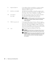
Insert the power cable. Access connectors for more information. Removing and Installing Parts 63 Back View of the Computer 1 2 3 4 1 voltage selection switch 2 power connector 3 back panel connectors 4 card slots See the safety instructions in the Product Information Guide for any installed PCI and PCI Express cards. Plug USB, audio, and other devices into the appropriate connector.
Insert the power cable. Access connectors for more information. Removing and Installing Parts 63 Back View of the Computer 1 2 3 4 1 voltage selection switch 2 power connector 3 back panel connectors 4 card slots See the safety instructions in the Product Information Guide for any installed PCI and PCI Express cards. Plug USB, audio, and other devices into the appropriate connector.

Owner's Manual
Page 66
Follow the procedures in "Before You Begin" on all computers. 66 Removing and Installing Parts power supply system board CD or DVD drive *floppy drive hard drive *May not be present on page 59. 4 Locate the three hinge tabs on the ...
Follow the procedures in "Before You Begin" on all computers. 66 Removing and Installing Parts power supply system board CD or DVD drive *floppy drive hard drive *May not be present on page 59. 4 Locate the three hinge tabs on the ...
Owner's Manual
Page 67
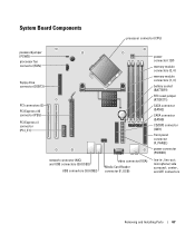
... connector (PEG) PCI Express x1 connector (PCI_E1) network connector (NIC) and USB connectors (2) (USB2) USB connectors (3) (USB2) video connector (VGA) Media Card Reader connector (F_USB) power connector (12V) memory module connectors (2, 4) memory module connectors (1, 3) battery socket (BATTERY) RTC reset jumper (RTCRST1) SATA connector (SATA2) SATA connector (SATA0) CD/DVD connector (IDE1...
... connector (PEG) PCI Express x1 connector (PCI_E1) network connector (NIC) and USB connectors (2) (USB2) USB connectors (3) (USB2) video connector (VGA) Media Card Reader connector (F_USB) power connector (12V) memory module connectors (2, 4) memory module connectors (1, 3) battery socket (BATTERY) RTC reset jumper (RTCRST1) SATA connector (SATA2) SATA connector (SATA0) CD/DVD connector (IDE1...


