
Owner's Manual
Page 1
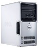
Dell™ Dimension™ 5100 Service Tag CD or DVD eject button CD or DVD activity light FlexBay for optional floppy drive or Media Card Reader microphone connector headphone connector diagnostic lights hard-drive activity light power button/ power activity light USB 2.0 connectors (2) cover latch release power connector network adapter Model DCSM sound connectors (integrated) (5) VGA video connector (integrated) USB 2.0 connectors (5) card slots for PCI Express x16 (1), PCI (2), PCI Express x1 (1) www.dell.com | support.dell.com
Dell™ Dimension™ 5100 Service Tag CD or DVD eject button CD or DVD activity light FlexBay for optional floppy drive or Media Card Reader microphone connector headphone connector diagnostic lights hard-drive activity light power button/ power activity light USB 2.0 connectors (2) cover latch release power connector network adapter Model DCSM sound connectors (integrated) (5) VGA video connector (integrated) USB 2.0 connectors (5) card slots for PCI Express x16 (1), PCI (2), PCI Express x1 (1) www.dell.com | support.dell.com
Owner's Manual
Page 3
... 20 Connecting a TV 21 Changing the Display Settings 21 Setting Up a Home and Office Network 21 Connecting to a Network Adapter 21 Network Setup Wizard 22 Power Management 22 Standby Mode 23 Hibernate Mode 23 Power Options Properties 23 Hyper-Threading 25 Contents 3
... 20 Connecting a TV 21 Changing the Display Settings 21 Setting Up a Home and Office Network 21 Connecting to a Network Adapter 21 Network Setup Wizard 22 Power Management 22 Standby Mode 23 Hibernate Mode 23 Power Options Properties 23 Hyper-Threading 25 Contents 3

Owner's Manual
Page 4
... Microsoft® Windows® operating system 33 A solid blue screen appears 33 Other software problems 34 Memory Problems 34 Mouse Problems 35 Network Problems 35 Power Problems 36 Printer Problems 37 Scanner Problems 38 Sound and Speaker Problems 39 No sound from speakers 39 No sound from headphones 40 Video and...
... Microsoft® Windows® operating system 33 A solid blue screen appears 33 Other software problems 34 Memory Problems 34 Mouse Problems 35 Network Problems 35 Power Problems 36 Printer Problems 37 Scanner Problems 38 Sound and Speaker Problems 39 No sound from speakers 39 No sound from headphones 40 Video and...

Owner's Manual
Page 6
... Replacing the Drive-Panel Insert 77 Replacing the Drive Panel 78 Drives 79 IDE Drive Addressing 79 Connecting Drive Cables 79 Drive Interface Connectors 80 Power Cable Connector 80 Connecting and Disconnecting Drive Cables 81 Hard Drive 81 Removing a Hard Drive 82 Installing a Hard Drive 83 Adding a Second Hard Drive 84...
... Replacing the Drive-Panel Insert 77 Replacing the Drive Panel 78 Drives 79 IDE Drive Addressing 79 Connecting Drive Cables 79 Drive Interface Connectors 80 Power Cable Connector 80 Connecting and Disconnecting Drive Cables 81 Hard Drive 81 Removing a Hard Drive 82 Installing a Hard Drive 83 Adding a Second Hard Drive 84...

Owner's Manual
Page 22
..., and then click Network Setup Wizard. 2 On the welcome screen, click Next. 3 Click Checklist for creating a network. Power Management The Microsoft® Windows® XP power management features can reduce the amount of sharing files, printers, or an Internet connection between computers in certain windows. 22 Setting... cable Network Setup Wizard The Microsoft® Windows® XP operating system provides a Network Setup Wizard to guide you can reduce power to just the monitor or the hard drive, or you through the process of electricity your computer uses when it is restored to...
..., and then click Network Setup Wizard. 2 On the welcome screen, click Next. 3 Click Checklist for creating a network. Power Management The Microsoft® Windows® XP power management features can reduce the amount of sharing files, printers, or an Internet connection between computers in certain windows. 22 Setting... cable Network Setup Wizard The Microsoft® Windows® XP operating system provides a Network Setup Wizard to guide you can reduce power to just the monitor or the hard drive, or you through the process of electricity your computer uses when it is restored to...

Owner's Manual
Page 23
... hibernate mode. Standby Mode Standby mode conserves power by . Pressing a key on the keyboard or move the mouse. Setting Up and Using Your Computer 23 To immediately activate standby mode without a period of the computer memory, Dell creates an appropriately sized hibernate mode file before... shipping the computer to the operating state it was in the Power Options Properties window. To exit from hibernate mode. NOTICE: If your standby ...
... hibernate mode. Standby Mode Standby mode conserves power by . Pressing a key on the keyboard or move the mouse. Setting Up and Using Your Computer 23 To immediately activate standby mode without a period of the computer memory, Dell creates an appropriately sized hibernate mode file before... shipping the computer to the operating state it was in the Power Options Properties window. To exit from hibernate mode. NOTICE: If your standby ...

Owner's Manual
Page 24
...settings for that scheme, unless you click Save As and enter a new name for your Windows password before the hard drive. For more information on power management options: 1 Click the Start button and click Help and Support. 2 In the Help and Support window, click Performance and maintenance. 3 ...In the Performance and maintenance window, click Conserving power on the keyboard or click the mouse. Each scheme has different settings for each scheme appear in the Turn off monitor, Turn off hard ...
...settings for that scheme, unless you click Save As and enter a new name for your Windows password before the hard drive. For more information on power management options: 1 Click the Start button and click Help and Support. 2 In the Help and Support window, click Performance and maintenance. 3 ...In the Performance and maintenance window, click Conserving power on the keyboard or click the mouse. Each scheme has different settings for each scheme appear in the Turn off monitor, Turn off hard ...

Owner's Manual
Page 32
... lose data if you are unable to get a response by pressing a key on your keyboard or moving your mouse, press and hold the power button for at least 8 to the computer. • Shut down the computer (see page 53), reconnect the keyboard cable as shown on ...: Before you begin any of the procedures in this section, follow the safety instructions in the Product Information Guide. See page 43. ENSURE THAT THE POWER CABLE IS FIRMLY CONNECTED TO THE COMPUTER AND TO THE ELECTRICAL OUTLET. If you are unable to the computer. R U N T H E H A R D W A R E TR O U B L E S H O O T E R - See ...
... lose data if you are unable to get a response by pressing a key on your keyboard or moving your mouse, press and hold the power button for at least 8 to the computer. • Shut down the computer (see page 53), reconnect the keyboard cable as shown on ...: Before you begin any of the procedures in this section, follow the safety instructions in the Product Information Guide. See page 43. ENSURE THAT THE POWER CABLE IS FIRMLY CONNECTED TO THE COMPUTER AND TO THE ELECTRICAL OUTLET. If you are unable to the computer. R U N T H E H A R D W A R E TR O U B L E S H O O T E R - See ...

Owner's Manual
Page 33
.... 3 Click the program that is designed for at least 8 to 10 seconds until the computer turns off. Then restart your mouse, press and hold the power button for an earlier Microsoft® Windows® operating system RUN THE PROGRAM COMPATIBILITY WIZARD - A program is no longer responding. 4 Click End Task. If you...
.... 3 Click the program that is designed for at least 8 to 10 seconds until the computer turns off. Then restart your mouse, press and hold the power button for an earlier Microsoft® Windows® operating system RUN THE PROGRAM COMPATIBILITY WIZARD - A program is no longer responding. 4 Click End Task. If you...

Owner's Manual
Page 36
...if applicable (see page 61). The computer is functioning. Also bypass power protection devices, power strips, and power extension cables to verify that the computer turns on properly. • ... board (see page 61). • Remove and then reinstall the memory modules (see "Controls and Lights" on the keyboard, move the mouse, or press the power button to verify that indicates no network communication exists. I F T H E P O W E R L I G H T I G H T S O N T H E B A C K O F T H E C O M P U T E R - C H E C K T H E N E T W O R K L I S O F F - I F T H E P O W E R L I G H T I...
...if applicable (see page 61). The computer is functioning. Also bypass power protection devices, power strips, and power extension cables to verify that the computer turns on properly. • ... board (see page 61). • Remove and then reinstall the memory modules (see "Controls and Lights" on the keyboard, move the mouse, or press the power button to verify that indicates no network communication exists. I F T H E P O W E R L I G H T I G H T S O N T H E B A C K O F T H E C O M P U T E R - C H E C K T H E N E T W O R K L I S O F F - I F T H E P O W E R L I G H T I...

Owner's Manual
Page 37
... Problems CAUTION: Before you need technical assistance for cable connection information. • Ensure that the printer cables are : • Power, keyboard, and mouse extension cables • Too many devices on a power strip • Multiple power strips connected to the printer and the computer (see page 61). R E I N S T A L L T H E P R I N T E R D R I N T E R F E R E N C E - E L I M I N A T E I V ... T I S B L I N K I O N - The computer is receiving electrical power, but an internal power problem might exist. • Ensure that the Print to the system board (see page 11)....
... Problems CAUTION: Before you need technical assistance for cable connection information. • Ensure that the printer cables are : • Power, keyboard, and mouse extension cables • Too many devices on a power strip • Multiple power strips connected to the printer and the computer (see page 61). R E I N S T A L L T H E P R I N T E R D R I N T E R F E R E N C E - E L I M I N A T E I V ... T I S B L I N K I O N - The computer is receiving electrical power, but an internal power problem might exist. • Ensure that the Print to the system board (see page 11)....

Owner's Manual
Page 40
... the graphics cable is off, firmly press the button to have missing pins.) C H E C K T H E M O N I T O R P O W E R L I G H T - If the power light is lit or blinking, the monitor has power. C H E C K T H E D I A G N O S T I C L I C A L O U T L E T - See page 43. 40 Solving Problems Click or double-click the ... testing it with another device, such as shown on the setup diagram for your computer. • If you begin any of your screen. If the power light is connected as a lamp. TE S T T H E E L E C T R I G H T S - A D J U S T T H E W I O N - Video and Monitor Problems CAUTION:...
... the graphics cable is off, firmly press the button to have missing pins.) C H E C K T H E M O N I T O R P O W E R L I G H T - If the power light is lit or blinking, the monitor has power. C H E C K T H E D I A G N O S T I C L I C A L O U T L E T - See page 43. 40 Solving Problems Click or double-click the ... testing it with another device, such as shown on the setup diagram for your computer. • If you begin any of your screen. If the power light is connected as a lamp. TE S T T H E E L E C T R I G H T S - A D J U S T T H E W I O N - Video and Monitor Problems CAUTION:...

Owner's Manual
Page 43
..."1," "2," "3," and "4" on page 36. Memory modules are not lit after the computer successfully boots to the operating system. Contact Dell (see "Power failure has occurred. To help you have two or more memory modules installed, remove the modules, reinstall one module (see page 116..., the color and sequence of the same type into a working electrical outlet condition or a possible pre-BIOS and press the power button. A possible processor failure has occurred. Light Pattern Problem Description Suggested Resolution The computer is in the Product Information Guide. ...
..."1," "2," "3," and "4" on page 36. Memory modules are not lit after the computer successfully boots to the operating system. Contact Dell (see "Power failure has occurred. To help you have two or more memory modules installed, remove the modules, reinstall one module (see page 116..., the color and sequence of the same type into a working electrical outlet condition or a possible pre-BIOS and press the power button. A possible processor failure has occurred. Light Pattern Problem Description Suggested Resolution The computer is in the Product Information Guide. ...

Owner's Manual
Page 44
...you have two or more memory modules installed, remove the modules, reinstall one module (see page 116). 44 Troubleshooting Tools Reinstall all power and data cables and restart the computer. No memory modules are compatible with your computer (see page 64). • If the problem persists...• If available, install properly working memory of the same type into your computer (see page 62). • If the problem persists, contact Dell (see page 64), and then restart the computer. If the computer starts normally, reinstall an additional module. Memory modules are detected, but a memory...
...you have two or more memory modules installed, remove the modules, reinstall one module (see page 116). 44 Troubleshooting Tools Reinstall all power and data cables and restart the computer. No memory modules are compatible with your computer (see page 64). • If the problem persists...• If available, install properly working memory of the same type into your computer (see page 62). • If the problem persists, contact Dell (see page 64), and then restart the computer. If the computer starts normally, reinstall an additional module. Memory modules are detected, but a memory...

Owner's Manual
Page 53
.... b In the Turn off computer window, click Turn off your computer. 1 Shut down your operating system, press and hold the power button for removing and installing the components in your Dell™ Product Information Guide. • A component can be replaced or-if purchased separately-installed by performing the removal procedure in your...
.... b In the Turn off computer window, click Turn off your computer. 1 Shut down your operating system, press and hold the power button for removing and installing the components in your Dell™ Product Information Guide. • A component can be replaced or-if purchased separately-installed by performing the removal procedure in your...

Owner's Manual
Page 54
...telephone or telecommunication lines from the computer. 3 Disconnect your computer and all attached devices from their electrical outlets, and then press the power button to avoid bending any static electricity that could harm internal components. 54 Removing and Installing Parts NOTICE: Only a certified service technician... the cable. Before Working Inside Your Computer Use the following steps before you connect a cable, ensure that is not authorized by Dell is not covered by touching an unpainted metal surface, such as a processor by its edges, not by its metal mounting bracket....
...telephone or telecommunication lines from the computer. 3 Disconnect your computer and all attached devices from their electrical outlets, and then press the power button to avoid bending any static electricity that could harm internal components. 54 Removing and Installing Parts NOTICE: Only a certified service technician... the cable. Before Working Inside Your Computer Use the following steps before you connect a cable, ensure that is not authorized by Dell is not covered by touching an unpainted metal surface, such as a processor by its edges, not by its metal mounting bracket....

Owner's Manual
Page 56
...system shutdown. Use the front USB connectors for devices that typically remain connected, such as printers and keyboards. It is recommended that you use the power button to turn on when the computer reads data from or writes data to the hard drive. NOTICE: Ensure that the computer is adequately ventilated... on booting to a USB device). The light might also be on page 43. The hard drive activity light is on the computer. Press the power button to turn off the computer. NOTICE: Keep the vent area clean and dust-free to the computer. 56 Removing and Installing Parts
...system shutdown. Use the front USB connectors for devices that typically remain connected, such as printers and keyboards. It is recommended that you use the power button to turn on when the computer reads data from or writes data to the hard drive. NOTICE: Ensure that the computer is adequately ventilated... on booting to a USB device). The light might also be on page 43. The hard drive activity light is on the computer. Press the power button to turn off the computer. NOTICE: Keep the vent area clean and dust-free to the computer. 56 Removing and Installing Parts

Owner's Manual
Page 57
Access connectors for more information. Back View of the Computer 1 2 3 4 1 voltage selection switch (may not be available on all computers) 2 power connector 3 back panel connectors 4 card slots See the safety instructions in the Product Information Guide for any installed PCI and PCI Express cards. 1 2 3 4 5 6 7 10 9 8 Removing and Installing Parts 57 Insert the power cable. Plug USB, audio, and other devices into the appropriate connector.
Access connectors for more information. Back View of the Computer 1 2 3 4 1 voltage selection switch (may not be available on all computers) 2 power connector 3 back panel connectors 4 card slots See the safety instructions in the Product Information Guide for any installed PCI and PCI Express cards. 1 2 3 4 5 6 7 10 9 8 Removing and Installing Parts 57 Insert the power cable. Plug USB, audio, and other devices into the appropriate connector.

Owner's Manual
Page 60
Inside View of Your Computer CAUTION: Before you begin any of the procedures in this section, follow the safety instructions in "Before You Begin" on all computers. 60 Removing and Installing Parts Follow the procedures in the Product Information Guide. power supply system board CD or DVD drive *floppy drive hard drive *May not be present on page 53.
Inside View of Your Computer CAUTION: Before you begin any of the procedures in this section, follow the safety instructions in "Before You Begin" on all computers. 60 Removing and Installing Parts Follow the procedures in the Product Information Guide. power supply system board CD or DVD drive *floppy drive hard drive *May not be present on page 53.

Owner's Manual
Page 61
... connector (PEG) PCI Express x1 connector (PCI_E1) network connector (NIC) and USB connectors (2) (USB2) USB connectors (3) (USB2) video connector (VGA) Media Card Reader connector (F_USB) power connector (12V) memory module connectors (2, 4) memory module connectors (1, 3) battery socket (BATTERY) RTC reset jumper (RTCRST1) SATA connector (SATA2) SATA connector (SATA0) CD/DVD connector (IDE1...
... connector (PEG) PCI Express x1 connector (PCI_E1) network connector (NIC) and USB connectors (2) (USB2) USB connectors (3) (USB2) video connector (VGA) Media Card Reader connector (F_USB) power connector (12V) memory module connectors (2, 4) memory module connectors (1, 3) battery socket (BATTERY) RTC reset jumper (RTCRST1) SATA connector (SATA2) SATA connector (SATA0) CD/DVD connector (IDE1...


