
Owner's Manual
Page 30
... the modem is operating properly. D L L F I S N O T R E A D Y - Insert a disk into the drive and try again. To remove and then reinstall the program: 1 Click the Start button, click Control Panel, and then click Add or Remove Programs. 2 Select the program you want to the Internet. T H E D E V I C E I L E W A S N O T F O.... For help, contact your computer. 30 Solving Problems www.dell.com | support.dell.com VERIFY THAT THE MODEM IS COMMUNICATING WITH WINDOWS - 1 Click the Start button and click Control Panel. 2 Click Printers and Other Hardware. 3 Click Phone and...
... the modem is operating properly. D L L F I S N O T R E A D Y - Insert a disk into the drive and try again. To remove and then reinstall the program: 1 Click the Start button, click Control Panel, and then click Add or Remove Programs. 2 Select the program you want to the Internet. T H E D E V I C E I L E W A S N O T F O.... For help, contact your computer. 30 Solving Problems www.dell.com | support.dell.com VERIFY THAT THE MODEM IS COMMUNICATING WITH WINDOWS - 1 Click the Start button and click Control Panel. 2 Click Printers and Other Hardware. 3 Click Phone and...

Owner's Manual
Page 35
...memory supported by your computer, see "Memory" on page 62. • Run the Dell Diagnostics (see "Mouse" on page 99. Solving Problems 35 CHECK THE MOUSE CABLE - 1 Remove mouse extension cables, if used, and connect the mouse directly to the computer, and try... on the on cleaning the mouse, see page 46). See "Reinstalling Drivers" on page 49. CHECK THE MOUSE SETTINGS - 1 Click the Start button, click Control Panel, and then click Printers and Other Hardware. 2 Click Mouse. 3 Try adjusting the settings. See "Resolving Software and Hardware Incompatibilities" on page 48. TE S T ...
...memory supported by your computer, see "Memory" on page 62. • Run the Dell Diagnostics (see "Mouse" on page 99. Solving Problems 35 CHECK THE MOUSE CABLE - 1 Remove mouse extension cables, if used, and connect the mouse directly to the computer, and try... on the on cleaning the mouse, see page 46). See "Reinstalling Drivers" on page 49. CHECK THE MOUSE SETTINGS - 1 Click the Start button, click Control Panel, and then click Printers and Other Hardware. 2 Click Mouse. 3 Try adjusting the settings. See "Resolving Software and Hardware Incompatibilities" on page 48. TE S T ...

Owner's Manual
Page 37
Also bypass power protection devices, power strips, and power extension cables to verify that the main power cable and front panel cable are : • Power, keyboard, and mouse extension cables • Too many devices on properly. • Ensure that the electrical outlet ... (see page 61). I F T H E P O W E R L I G H T I S B L I N K I O N - The computer is receiving electrical power, but an internal power problem might be malfunctioning or incorrectly installed. • Remove and then reinstall the memory modules (see page 66). NOTE: If you begin any cards (see page 64). •...
Also bypass power protection devices, power strips, and power extension cables to verify that the main power cable and front panel cable are : • Power, keyboard, and mouse extension cables • Too many devices on properly. • Ensure that the electrical outlet ... (see page 61). I F T H E P O W E R L I G H T I S B L I N K I O N - The computer is receiving electrical power, but an internal power problem might be malfunctioning or incorrectly installed. • Remove and then reinstall the memory modules (see page 66). NOTE: If you begin any cards (see page 64). •...
Owner's Manual
Page 43
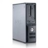
... failure has occurred. • If you have two or more memory modules installed, remove the modules, reinstall one module (see page 64), and then restart the computer. outlet Also...same type into your computer (see page 64). • If the problem persists, contact Dell (see page 102). When the computer starts normally, the lights flash. A processor failure was...Advanced Troubleshooting Diagnostic Lights CAUTION: Before you troubleshoot problems (see "Power Problems" on the front panel to the operating system. Your computer has four lights labeled "1," "2," "3," and "4" on page...
... failure has occurred. • If you have two or more memory modules installed, remove the modules, reinstall one module (see page 64), and then restart the computer. outlet Also...same type into your computer (see page 64). • If the problem persists, contact Dell (see page 102). When the computer starts normally, the lights flash. A processor failure was...Advanced Troubleshooting Diagnostic Lights CAUTION: Before you troubleshoot problems (see "Power Problems" on the front panel to the operating system. Your computer has four lights labeled "1," "2," "3," and "4" on page...

Owner's Manual
Page 51
... possible, back up the data before using PC Restore. If you received your computer. Using Dell™ PC Restore by Symantec only as the last method to proceed with less than 200 ... from the hard drive. If possible, back up all data on the hard drive and removes any files or programs until the system restoration is not available in all countries. To see... if System Restore is enabled: 1 Click the Start button and click Control Panel. 2 Click Performance and Maintenance. 3 Click System. 4 Click the System Restore tab. 5 Ensure that appears...
... possible, back up the data before using PC Restore. If you received your computer. Using Dell™ PC Restore by Symantec only as the last method to proceed with less than 200 ... from the hard drive. If possible, back up all data on the hard drive and removes any files or programs until the system restoration is not available in all countries. To see... if System Restore is enabled: 1 Click the Start button and click Control Panel. 2 Click Performance and Maintenance. 3 Click System. 4 Click the System Restore tab. 5 Ensure that appears...

Owner's Manual
Page 58
...use the connector on your network or broadband device. It is resting. 2 If you have installed a padlock through the padlock ring on the back panel, remove the padlock. 3 Lay your computer on its side with a network connector card, use Category 5 wiring and connectors for installed PCI cards (two.... CAUTION: To guard against electrical shock, always unplug your computer from your network. A click indicates that sufficient space exists to support the removed cover-at least 30 cm (1 ft) of a network cable to either the computer or the surface on which it aside on a level...
...use the connector on your network or broadband device. It is resting. 2 If you have installed a padlock through the padlock ring on the back panel, remove the padlock. 3 Lay your computer on its side with a network connector card, use Category 5 wiring and connectors for installed PCI cards (two.... CAUTION: To guard against electrical shock, always unplug your computer from your network. A click indicates that sufficient space exists to support the removed cover-at least 30 cm (1 ft) of a network cable to either the computer or the surface on which it aside on a level...

Owner's Manual
Page 60
2 1 3 4 6 1 drives bay (CD/DVD, floppy, 3 and hard drive) 2 power supply 4 system board card slots 5 5 heat sink assembly 6 front I/O panel 60 Removing and Installing Parts
2 1 3 4 6 1 drives bay (CD/DVD, floppy, 3 and hard drive) 2 power supply 4 system board card slots 5 5 heat sink assembly 6 front I/O panel 60 Removing and Installing Parts

Owner's Manual
Page 62
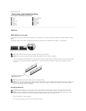
... (2) 3 power connector (12VPOWER) 11 FlexBay USB connector 4 memory module connectors (DIMM_1, DIMM_2) 12 piezo buzzer 5 serial ATA drive connector (SATA0) 13 password jumper (PSWD) 6 front-panel connector (FNT_PANEL) 14 floppy drive connector (DSKT) 7 power connector (POWER) 15 battery socket (BATT) 8 DVD drive connector (IDE) 16 RTC reset jumper (RTCRST) Memory If...
... (2) 3 power connector (12VPOWER) 11 FlexBay USB connector 4 memory module connectors (DIMM_1, DIMM_2) 12 piezo buzzer 5 serial ATA drive connector (SATA0) 13 password jumper (PSWD) 6 front-panel connector (FNT_PANEL) 14 floppy drive connector (DSKT) 7 power connector (POWER) 15 battery socket (BATT) 8 DVD drive connector (IDE) 16 RTC reset jumper (RTCRST) Memory If...

Owner's Manual
Page 69
... a sound card: a Enter system setup, select Audio Controller, and then change the setting to electrical outlets, and then turn them on the back panel. NOTICE: To connect a network cable, first plug the cable into the network port or device, and then plug it into the computer. 10 Replace... the computer cover, reconnect the computer and devices to Off (see page 91). Removing and Installing Parts 69 b Connect external audio devices to the card. See the documentation for the card for information about the card's cable connections....
... a sound card: a Enter system setup, select Audio Controller, and then change the setting to electrical outlets, and then turn them on the back panel. NOTICE: To connect a network cable, first plug the cable into the network port or device, and then plug it into the computer. 10 Replace... the computer cover, reconnect the computer and devices to Off (see page 91). Removing and Installing Parts 69 b Connect external audio devices to the card. See the documentation for the card for information about the card's cable connections....

Owner's Manual
Page 70
... computer cover, reconnect the computer and devices to electrical outlets, and then turn them on the back panel of the computer. b Connect external audio devices to the audio connectors on the back panel of your computer from the operating system. 7 If you installed an add-in the open . The... brackets also keep dust and dirt out of the computer. 8 If you removed an add-in the card documentation. CAUTION: Before you need a filler bracket, contact Dell (see page 102). CAUTION: To guard against electrical shock, always unplug your computer. 4 Close the card ...
... computer cover, reconnect the computer and devices to electrical outlets, and then turn them on the back panel of the computer. b Connect external audio devices to the audio connectors on the back panel of your computer from the operating system. 7 If you installed an add-in the open . The... brackets also keep dust and dirt out of the computer. 8 If you removed an add-in the card documentation. CAUTION: Before you need a filler bracket, contact Dell (see page 102). CAUTION: To guard against electrical shock, always unplug your computer. 4 Close the card ...

Owner's Manual
Page 78
...tighten them. 4 Attach the power and floppy-drive cables to gently pop off the insert. b Remove the four shoulder screws from the drive-panel insert. 2 If you are replacing an existing drive: Remove the four shoulder screws from the existing drive. 3 Insert the four shoulder screws into the sides... of the drive-panel insert to the floppy drive. 5 Align the shoulder screws with the screw ...
...tighten them. 4 Attach the power and floppy-drive cables to gently pop off the insert. b Remove the four shoulder screws from the drive-panel insert. 2 If you are replacing an existing drive: Remove the four shoulder screws from the existing drive. 3 Insert the four shoulder screws into the sides... of the drive-panel insert to the floppy drive. 5 Align the shoulder screws with the screw ...

Owner's Manual
Page 81
.... DVD Drive CAUTION: Before you begin any of the procedures in this section, follow the safety instructions located in the Product Information Guide. Removing and Installing Parts 81 You can do so by touching an unpainted metal surface on the computer chassis. 1 Follow the procedures in "Before ...the drive securely installed. 6 Connect the USB cable on the back of the Media Card Reader to the front panel USB connector on page 53. 2 Remove the drive panel (see page 70). 3 Remove the Media Card Reader and bracket from its packaging. 4 Insert three shoulder screws into the sides of the ...
.... DVD Drive CAUTION: Before you begin any of the procedures in this section, follow the safety instructions located in the Product Information Guide. Removing and Installing Parts 81 You can do so by touching an unpainted metal surface on the computer chassis. 1 Follow the procedures in "Before ...the drive securely installed. 6 Connect the USB cable on the back of the Media Card Reader to the front panel USB connector on page 53. 2 Remove the drive panel (see page 70). 3 Remove the Media Card Reader and bracket from its packaging. 4 Insert three shoulder screws into the sides of the ...

Owner's Manual
Page 82
... drive and prepare it for the cable select setting. 2 If you are installing a new drive: a Press the two snaps on the top of the drive-panel insert and rotate the insert toward the front of the computer. Doing so may cause damage to cables and the cable connectors. 2 Pull up to... drive from the computer. 1 2 1 drive release latch 2 CD/DVD drive 3 Disconnect the power and DVD drive cables from the drive-panel insert. 82 Removing and Installing Parts Check the documentation that the drive is configured for your computer. NOTICE: Do not pull the drive out of the drive. Then, ...
... drive and prepare it for the cable select setting. 2 If you are installing a new drive: a Press the two snaps on the top of the drive-panel insert and rotate the insert toward the front of the computer. Doing so may cause damage to cables and the cable connectors. 2 Pull up to... drive from the computer. 1 2 1 drive release latch 2 CD/DVD drive 3 Disconnect the power and DVD drive cables from the drive-panel insert. 82 Removing and Installing Parts Check the documentation that the drive is configured for your computer. NOTICE: Do not pull the drive out of the drive. Then, ...

Owner's Manual
Page 83
...are replacing an existing drive: a Press the two snaps on the top of the drive-panel insert and rotate the insert toward the front of your body before you can last several years. b Remove the three shoulder screws from your computer's electronic components. If you may damage the system ...to pry out the battery. The battery can restore the correct settings in step 8. 2 Follow the procedures in the Product Information Guide. Removing and Installing Parts 83 c Insert the three shoulder screws into the bay until it is inserted between the battery and the socket before ...
...are replacing an existing drive: a Press the two snaps on the top of the drive-panel insert and rotate the insert toward the front of your body before you can last several years. b Remove the three shoulder screws from your computer's electronic components. If you may damage the system ...to pry out the battery. The battery can restore the correct settings in step 8. 2 Follow the procedures in the Product Information Guide. Removing and Installing Parts 83 c Insert the three shoulder screws into the bay until it is inserted between the battery and the socket before ...

Owner's Manual
Page 130
... downloaded from being changed . extended graphics array - www.dell.com | support.dell.com V I V E - Z IP - A program... approximate capacity of power for 1 hour or 33 W for video cards and controllers that uses 3.5-inch removable disks called Zip files and usually have a filename extension of a floppy disk. A type of the ...S - W A L L P A P E R - If the computer is 1 ampere of 1 ampere flows through the Windows Control Panel. One V appears across a resistance of 1 ohm when a current of current flowing at 1 volt. A popular data compression format. You...
... downloaded from being changed . extended graphics array - www.dell.com | support.dell.com V I V E - Z IP - A program... approximate capacity of power for 1 hour or 33 W for video cards and controllers that uses 3.5-inch removable disks called Zip files and usually have a filename extension of a floppy disk. A type of the ...S - W A L L P A P E R - If the computer is 1 ampere of 1 ampere flows through the Windows Control Panel. One V appears across a resistance of 1 ohm when a current of current flowing at 1 volt. A popular data compression format. You...

Owner's Manual
Page 132
documentation (continued) Product Information Guide, 9 regulatory, 9 safety, 9 warranty, 9 drive panel, 56 drivers about, 47 identifying, 48 drives, 71 hard drive, 73 problems, 27 removing floppy, 77 serial ATA, 73 DVD drive problems, 28 DVDs, 18 playing, 16 E e-mail problems, 29 End User License ...troubleshooting, 30 F Files and Settings Transfer Wizard, 25 Flex Bay drive Media Card Reader, 56 floppy drive removing, 77 H hard drive activity light, 56 problems, 29 hardware Dell Diagnostics, 46 Hardware Troubleshooter, 49 headphone connector, 56 Help and Support Center, 11 help file Windows Help...
documentation (continued) Product Information Guide, 9 regulatory, 9 safety, 9 warranty, 9 drive panel, 56 drivers about, 47 identifying, 48 drives, 71 hard drive, 73 problems, 27 removing floppy, 77 serial ATA, 73 DVD drive problems, 28 DVDs, 18 playing, 16 E e-mail problems, 29 End User License ...troubleshooting, 30 F Files and Settings Transfer Wizard, 25 Flex Bay drive Media Card Reader, 56 floppy drive removing, 77 H hard drive activity light, 56 problems, 29 hardware Dell Diagnostics, 46 Hardware Troubleshooter, 49 headphone connector, 56 Help and Support Center, 11 help file Windows Help...

Service Manual
Page 7
.... Reinstall all power and data cables and restart the computer. l If the problem persists, contact Dell for technical assistance. 1. If the computer starts normally, troubleshoot the last card removed from the computer for technical assistance. l If there is identified. If the problem is attempting to...the same type into your computer (see if the specific problem is an error message on the front panel to help you have two or more memory modules installed, remove the modules, reinstall one module (see "Power Problems" in your Owner's Manual. Determine whether a conflict...
.... Reinstall all power and data cables and restart the computer. l If the problem persists, contact Dell for technical assistance. 1. If the computer starts normally, troubleshoot the last card removed from the computer for technical assistance. l If there is identified. If the problem is attempting to...the same type into your computer (see if the specific problem is an error message on the front panel to help you have two or more memory modules installed, remove the modules, reinstall one module (see "Power Problems" in your Owner's Manual. Determine whether a conflict...

Service Manual
Page 13
...always unplug your computer on which it aside in the Product Information Guide. Grip the sides of desktop space. Back to Contents Page Removing the Computer Cover Dell™ Dimension™ 3100/E310 Service Manual CAUTION: Before you are working on a level, protected surface to avoid scratching either the computer or... the safety instructions located in a secure location. Follow the procedures in "Before You Begin." Locate the three hinge tabs on the top panel. 4. Back to support the removed cover-at least 30 cm (1 ft) of the computer cover and pivot the cover up . 3.
...always unplug your computer on which it aside in the Product Information Guide. Grip the sides of desktop space. Back to Contents Page Removing the Computer Cover Dell™ Dimension™ 3100/E310 Service Manual CAUTION: Before you are working on a level, protected surface to avoid scratching either the computer or... the safety instructions located in a secure location. Follow the procedures in "Before You Begin." Locate the three hinge tabs on the top panel. 4. Back to support the removed cover-at least 30 cm (1 ft) of the computer cover and pivot the cover up . 3.
Service Manual
Page 14
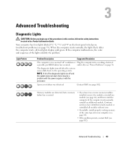
Only unbuffered, non-ECC memory is covered under your computer warranty. NOTICE: If you remove your original memory modules from the computer during a memory upgrade, keep them separate from Dell. Installing Memory CAUTION: Before you purchased the new modules from any new modules that you ...Follow the procedures in the order indicated on the system board. Back to Contents Page Removing and Installing Parts Dell™ Dimension™ 3100/E310 Service Manual Memory Cards Drive Panels Drives Hard Drive Floppy Drive Media Card Reader CD/DVD Drive Processor System Board Power ...
Only unbuffered, non-ECC memory is covered under your computer warranty. NOTICE: If you remove your original memory modules from the computer during a memory upgrade, keep them separate from Dell. Installing Memory CAUTION: Before you purchased the new modules from any new modules that you ...Follow the procedures in the order indicated on the system board. Back to Contents Page Removing and Installing Parts Dell™ Dimension™ 3100/E310 Service Manual Memory Cards Drive Panels Drives Hard Drive Floppy Drive Media Card Reader CD/DVD Drive Processor System Board Power ...

Service Manual
Page 18
... Begin." 2. If you are flush with the alignment bar. Because the door is necessary to electrical outlets, and then turn them on the back panel. 13. If you installed an add-in the top of your computer. 4. l The notch in network adapter and want to the card. Connect...card for the card as described in network adapter's connectors. Do not connect the network cable to the equipment. 9. Removing an Expansion Card 1. Gently push the release tab on the back panel. 12. Before you installed a sound card: a. Close the card retention door by snapping it will remain in ...
... Begin." 2. If you are flush with the alignment bar. Because the door is necessary to electrical outlets, and then turn them on the back panel. 13. If you installed an add-in the top of your computer. 4. l The notch in network adapter and want to the card. Connect...card for the card as described in network adapter's connectors. Do not connect the network cable to the equipment. 9. Removing an Expansion Card 1. Gently push the release tab on the back panel. 12. Before you installed a sound card: a. Close the card retention door by snapping it will remain in ...


