
Owner's Manual
Page 10
.... DSS provides critical updates for your operating system and support for your computer and operating system and installs the updates appropriate for Dell™ 3.5-inch USB floppy drives, Intel® Pentium® M processors, optical drives, and USB devices. Contact information, service call status and support history, service contract, online discussions with other...
.... DSS provides critical updates for your operating system and support for your computer and operating system and installs the updates appropriate for Dell™ 3.5-inch USB floppy drives, Intel® Pentium® M processors, optical drives, and USB devices. Contact information, service call status and support history, service contract, online discussions with other...
Owner's Manual
Page 30
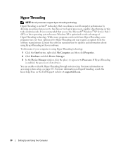
...dell.com. 30 Setting Up and Using Your Computer While many programs can benefit from the software manufacturer. You can enhance overall computer performance by allowing one physical processor to function as two logical processors, capable of Hyper-Threading technology. Hyper-Threading NOTE: Not all processors... of performing certain tasks simultaneously. To determine if your software. Hyper-Threading is listed twice. If Hyper-Threading is enabled, the processor is an Intel® technology that you use the Microsoft® Windows® XP Service Pack 1 (SP1) or later operating...
...dell.com. 30 Setting Up and Using Your Computer While many programs can benefit from the software manufacturer. You can enhance overall computer performance by allowing one physical processor to function as two logical processors, capable of Hyper-Threading technology. Hyper-Threading NOTE: Not all processors... of performing certain tasks simultaneously. To determine if your software. Hyper-Threading is listed twice. If Hyper-Threading is enabled, the processor is an Intel® technology that you use the Microsoft® Windows® XP Service Pack 1 (SP1) or later operating...

Owner's Manual
Page 41
... electrical outlet is securely connected to the system board (see page 69). I F T H E P O W E R L I G H T I N G A M B E R - E L I M I N A T E I O N - See the printer documentation for your location (if applicable). • Ensure that the processor power cable is working by testing it with another device, such as a lamp. • Ensure that the computer turns on . C H E C K T H E P R I N T E R D O C U M E N T A T I N T E R F E R E N C E - I F T H E P O W E R L I G H T I S O F F -
... electrical outlet is securely connected to the system board (see page 69). I F T H E P O W E R L I G H T I N G A M B E R - E L I M I N A T E I O N - See the printer documentation for your location (if applicable). • Ensure that the processor power cable is working by testing it with another device, such as a lamp. • Ensure that the computer turns on . C H E C K T H E P R I N T E R D O C U M E N T A T I N T E R F E R E N C E - I F T H E P O W E R L I G H T I S O F F -
Owner's Manual
Page 47
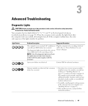
...outlet Also see "Power Problems" in your computer (see "Installing Memory" on page 67"), and then restart the computer. Contact Dell for technical assistance. Light Pattern Problem Description Suggested Resolution The computer is in the Product Information Guide. successfully boots to help you... working electrical a possible pre-BIOS failure has occurred. NOTE: If all four lights turn off after the system Owner's Manual. A processor failure was detected. Continue until you have two or more memory modules installed, remove the modules, reinstall one module (see page 59)....
...outlet Also see "Power Problems" in your computer (see "Installing Memory" on page 67"), and then restart the computer. Contact Dell for technical assistance. Light Pattern Problem Description Suggested Resolution The computer is in the Product Information Guide. successfully boots to help you... working electrical a possible pre-BIOS failure has occurred. NOTE: If all four lights turn off after the system Owner's Manual. A processor failure was detected. Continue until you have two or more memory modules installed, remove the modules, reinstall one module (see page 59)....

Owner's Manual
Page 50
... four diagnostic lights stay on and the Unplug the power supply and check the 4-pin power button remains amber, a possible processor power cable connection (see processor power or connection error has "System Board Components" on and then turn off and the system does not start , plug ...the lights turn on then does not start, contact Dell for technical off before the computer into a working electrical outlet. For other possible...
... four diagnostic lights stay on and the Unplug the power supply and check the 4-pin power button remains amber, a possible processor power cable connection (see processor power or connection error has "System Board Components" on and then turn off and the system does not start , plug ...the lights turn on then does not start, contact Dell for technical off before the computer into a working electrical outlet. For other possible...

Owner's Manual
Page 60
...bending any connector pins. CAUTION: Before you begin working inside your computer, ground yourself by touching an unpainted metal surface, such as a processor by its edges, not by its strain-relief loop, not on its metal mounting bracket. CAUTION: Handle components and cards with locking tabs;...anything inside the computer. 1 Turn off your computer (see page 62). Also, before you begin any static electricity that is not authorized by Dell is not covered by your warranty. Hold a card by its edges or by its pins. Some cables have a connector with care. Before...
...bending any connector pins. CAUTION: Before you begin working inside your computer, ground yourself by touching an unpainted metal surface, such as a processor by its edges, not by its strain-relief loop, not on its metal mounting bracket. CAUTION: Handle components and cards with locking tabs;...anything inside the computer. 1 Turn off your computer (see page 62). Also, before you begin any static electricity that is not authorized by Dell is not covered by your warranty. Hold a card by its edges or by its pins. Some cables have a connector with care. Before...

Owner's Manual
Page 67
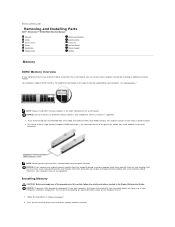
... connector memory module connectors (1, 2) SATA connectors (SATA-0 and SATA-1) processor and heat sink connector front panel I/O connector main power connector IDE drive connector floppy drive connector (FLOPPY) FlexBay USB connector fan connector (CPU FAN) clear ...
... connector memory module connectors (1, 2) SATA connectors (SATA-0 and SATA-1) processor and heat sink connector front panel I/O connector main power connector IDE drive connector floppy drive connector (FLOPPY) FlexBay USB connector fan connector (CPU FAN) clear ...

Owner's Manual
Page 68
...warranty. 66 Removing and Installing Parts If the DDR2 memory modules are not installed in matched pairs, the computer will continue to the processor, before you install mixed pairs of matched memory size, speed, and technology. See the label on the system board. The recommended memory... NOTICE: Do not install ECC or buffered memory modules. NOTE: Always install DDR2 memory modules in DIMM connectors 1 and 2 NOTE: Memory purchased from Dell is supported. • If you install a module in the other connector. 1 2 matched pair of memory modules in the order indicated on the module...
...warranty. 66 Removing and Installing Parts If the DDR2 memory modules are not installed in matched pairs, the computer will continue to the processor, before you install mixed pairs of matched memory size, speed, and technology. See the label on the system board. The recommended memory... NOTICE: Do not install ECC or buffered memory modules. NOTE: Always install DDR2 memory modules in DIMM connectors 1 and 2 NOTE: Memory purchased from Dell is supported. • If you install a module in the other connector. 1 2 matched pair of memory modules in the order indicated on the module...

Owner's Manual
Page 69
NOTICE: To prevent static damage to processor securing clips (2) connector 3 Align the notch on the bottom of the module with a new memory module. Installing Memory CAUTION: Before you begin any of your computer's electronic components. memory connector closest to components inside your computer, discharge static electricity from Dell. Otherwise, your computer may have...
NOTICE: To prevent static damage to processor securing clips (2) connector 3 Align the notch on the bottom of the module with a new memory module. Installing Memory CAUTION: Before you begin any of your computer's electronic components. memory connector closest to components inside your computer, discharge static electricity from Dell. Otherwise, your computer may have...

Owner's Manual
Page 101
... channels Interrupt levels BIOS chip (NVRAM) NIC System clock Intel® Pentium® 4 with Hyper-Threading technology NOTE: Not all Pentium 4 processors support Hyper-Threading technology. Intel Celeron® D processors At least 16 KB At least 256 KB (dependent upon your computer configuration) pipelined-burst, eight-way set associative, write-back SRAM...
... channels Interrupt levels BIOS chip (NVRAM) NIC System clock Intel® Pentium® 4 with Hyper-Threading technology NOTE: Not all Pentium 4 processors support Hyper-Threading technology. Intel Celeron® D processors At least 16 KB At least 256 KB (dependent upon your computer configuration) pipelined-burst, eight-way set associative, write-back SRAM...

Owner's Manual
Page 106
... appears below the Option Field and lists keys and their functions within the active system setup field. Identifies whether the computer's processor supports Hyper-Threading and lists the processor bus speed, processor ID, clock speed, and L2 cache. 104 Appendix In this section may not appear, or may not appear exactly as the...
... appears below the Option Field and lists keys and their functions within the active system setup field. Identifies whether the computer's processor supports Hyper-Threading and lists the processor bus speed, processor ID, clock speed, and L2 cache. 104 Appendix In this section may not appear, or may not appear exactly as the...

Owner's Manual
Page 108
... . Sets the computer to be assigned and verified. or left-arrow key to be noisier. NOTE: Changing the acoustics setting does not alter your computer's processor supports Hyper-Threading, this option appears in the Options List. • Bypass (default) - Choices are every day or every Monday through Friday. The default setting...
... . Sets the computer to be assigned and verified. or left-arrow key to be noisier. NOTE: Changing the acoustics setting does not alter your computer's processor supports Hyper-Threading, this option appears in the Options List. • Bypass (default) - Choices are every day or every Monday through Friday. The default setting...

Owner's Manual
Page 138
...specifications (continued) drives, 100 environmental, 102 expansion bus, 100 memory, 99 physical, 102 power, 102 processor, 99 technical, 99 video, 100 standby mode, 23 support contacting Dell, 114 policy, 112 support website, 10 system board, 65 System Restore, 53-54 system setup about,... 103 entering, 103 options, 104 screens, 103 T technical support policy, 112 transferring information to a new computer, 30 troubleshooting Dell Diagnostics, 50 diagnostic lights, 47 Hardware Troubleshooter, 53 Help and Support Center, 11 troubleshooting (continued) restore to previous state, 53-54...
...specifications (continued) drives, 100 environmental, 102 expansion bus, 100 memory, 99 physical, 102 power, 102 processor, 99 technical, 99 video, 100 standby mode, 23 support contacting Dell, 114 policy, 112 support website, 10 system board, 65 System Restore, 53-54 system setup about,... 103 entering, 103 options, 104 screens, 103 T technical support policy, 112 transferring information to a new computer, 30 troubleshooting Dell Diagnostics, 50 diagnostic lights, 47 Hardware Troubleshooter, 53 Help and Support Center, 11 troubleshooting (continued) restore to previous state, 53-54...

Service Manual
Page 7
... diagnostic lights turn off and the system does not start, there may be a problem with the power supply or with the processor. Memory modules are compatible with your computer Owner's Manual). 4. Reseat all four lights turn off " condition or a possible ..."). Continue until you removed, remove a different card, and then restart the computer. 3. l If the problem persists, contact Dell for technical assistance. A processor failure was detected. Continue until you troubleshoot problems. When the computer starts normally, the lights flash. A possible floppy drive or...
... diagnostic lights turn off and the system does not start, there may be a problem with the power supply or with the processor. Memory modules are compatible with your computer Owner's Manual). 4. Reseat all four lights turn off " condition or a possible ..."). Continue until you removed, remove a different card, and then restart the computer. 3. l If the problem persists, contact Dell for technical assistance. A processor failure was detected. Continue until you troubleshoot problems. When the computer starts normally, the lights flash. A possible floppy drive or...

Service Manual
Page 8
l If the problem persists, contact Dell for technical assistance. Also see "Power Problems" in your computer. If all four diagnostic lights stay on your Owner's Manual. Unplug the power supply and check the 4-pin processor power cable connection (see "Processor"). One possible beep code (code ...1-3-1) consists of one beep, a burst of the diagnostic lights turn on and then turn If the system does not start -up : 1. Write down the beep codes. 2. Contact Dell for technical assistance...
l If the problem persists, contact Dell for technical assistance. Also see "Power Problems" in your computer. If all four diagnostic lights stay on your Owner's Manual. Unplug the power supply and check the 4-pin processor power cable connection (see "Processor"). One possible beep code (code ...1-3-1) consists of one beep, a burst of the diagnostic lights turn on and then turn If the system does not start -up : 1. Write down the beep codes. 2. Contact Dell for technical assistance...

Service Manual
Page 10
...by its edges or by its metal mounting bracket. Also, before you begin working inside the computer. 1. Hold a component such as a processor by its edges, not by its pins. if you shut down the operating system: a. Turn off after the operating system shutdown process finishes... unplug the cable from your computer and then unplug it from potential damage and to Contents Page Before You Begin Dell™ Dimension™ 3100/E310 Service Manual Getting Started Recommended Tools Turning Off Your Computer Before Working Inside Your Computer Getting Started This section provides...
...by its edges or by its metal mounting bracket. Also, before you begin working inside the computer. 1. Hold a component such as a processor by its edges, not by its pins. if you shut down the operating system: a. Turn off after the operating system shutdown process finishes... unplug the cable from your computer and then unplug it from potential damage and to Contents Page Before You Begin Dell™ Dimension™ 3100/E310 Service Manual Getting Started Recommended Tools Turning Off Your Computer Before Working Inside Your Computer Getting Started This section provides...
Service Manual
Page 14
...your computer's electronic components. If possible, do so by installing an additional memory module. NOTICE: To prevent static damage to the processor, before you touch any of the memory module connector. Only unbuffered, non-ECC memory is covered under your computer, see "Specifications."...the system board. Back to Contents Page Removing and Installing Parts Dell™ Dimension™ 3100/E310 Service Manual Memory Cards Drive Panels Drives Hard Drive Floppy Drive Media Card Reader CD/DVD Drive Processor System Board Power Supply Battery Memory DDR2 Memory Overview If your...
...your computer's electronic components. If possible, do so by installing an additional memory module. NOTICE: To prevent static damage to the processor, before you touch any of the memory module connector. Only unbuffered, non-ECC memory is covered under your computer, see "Specifications."...the system board. Back to Contents Page Removing and Installing Parts Dell™ Dimension™ 3100/E310 Service Manual Memory Cards Drive Panels Drives Hard Drive Floppy Drive Media Card Reader CD/DVD Drive Processor System Board Power Supply Battery Memory DDR2 Memory Overview If your...

Service Manual
Page 15
... closest to each end of the module. 5. Insert the module into the connector until the module snaps into the connector while applying equal force to processor 2 securing clips (2) 3 connector 3. Right-click the My Computer icon and click Properties. 10. Click the General tab. 11. If you insert the module correctly, the...
... closest to each end of the module. 5. Insert the module into the connector until the module snaps into the connector while applying equal force to processor 2 securing clips (2) 3 connector 3. Right-click the My Computer icon and click Properties. 10. Click the General tab. 11. If you insert the module correctly, the...

Service Manual
Page 33
... instructions on each side of the heat sink and fan shroud assembly, you touch it. Enter system setup and select the appropriate Drive option. 10. Processor CAUTION: Before you begin any software required for the fan and cooling vents. 6. NOTE: To loosen the two captive screws on installing any of the... to the drive. 1 data cable 2 power cable 5. CAUTION: Despite having a plastic shield, the heat sink assembly may be very hot during normal operation. Removing the Processor 1. Connect your computer works correctly by running the...
... instructions on each side of the heat sink and fan shroud assembly, you touch it. Enter system setup and select the appropriate Drive option. 10. Processor CAUTION: Before you begin any software required for the fan and cooling vents. 6. NOTE: To loosen the two captive screws on installing any of the... to the drive. 1 data cable 2 power cable 5. CAUTION: Despite having a plastic shield, the heat sink assembly may be very hot during normal operation. Removing the Processor 1. Connect your computer works correctly by running the...

Service Manual
Page 34
... not touch any of the pins inside the socket or allow any objects to fall on the socket. Gently remove the processor from Dell, discard the original heat sink. 3. Rotate the heat sink and fan shroud assembly upward, and remove it from the computer. 1 heat sink ...and fan shroud assembly 2 captive screw housings (2) NOTICE: If you are not installing a processor upgrade kit from Dell, reuse the original heat sink when you are installing a processor upgrade kit from the socket. Open the processor cover by touching an unpainted metal surface on the pins in the release position so that...
... not touch any of the pins inside the socket or allow any objects to fall on the socket. Gently remove the processor from Dell, discard the original heat sink. 3. Rotate the heat sink and fan shroud assembly upward, and remove it from the computer. 1 heat sink ...and fan shroud assembly 2 captive screw housings (2) NOTICE: If you are not installing a processor upgrade kit from Dell, reuse the original heat sink when you are installing a processor upgrade kit from the socket. Open the processor cover by touching an unpainted metal surface on the pins in the release position so that...


