
Dell Dimension 2100 Solutions Guide
Page 82
... KB) PCI (version 2.2) PCI: 33 MHz supports four three-quarter-length cards 120 pins 32 bits 82 Appendix www.dell.com | support.dell.com Microprocessor Microprocessor type L1 cache L2 cache: Pentium III processors Celeron processors System Information System chip set DMA channels Interrupt ...levels System BIOS chip Expansion Bus Bus types Bus speed PCI connectors PCI connector size PCI connector data width (maximum) ...
... KB) PCI (version 2.2) PCI: 33 MHz supports four three-quarter-length cards 120 pins 32 bits 82 Appendix www.dell.com | support.dell.com Microprocessor Microprocessor type L1 cache L2 cache: Pentium III processors Celeron processors System Information System chip set DMA channels Interrupt ...levels System BIOS chip Expansion Bus Bus types Bus speed PCI connectors PCI connector size PCI connector data width (maximum) ...

Dell Dimension 2100 Solutions Guide
Page 135
... error messages, 25 video and monitor, 26 Windows error messages, 39 floppy drive fixing problems, 35 Index 135 See sound B battery disposal, 88 replacing, 88 BIOS, 86 C cards adding, 73 connectors, 66 removing, 77 CD drive fixing problems, 36 CD-RW drive fixing problems, 38 computer crashes, 40 error messages, 25..., 80 specifications, 82 turning off, 18 conflicts resolving software and hardware incompatibilities, 46 connectors, 66 contact numbers, 92 cover removing, 60 replacing, 80 crashes, 40 D Dell support policy, 90 display.
... error messages, 25 video and monitor, 26 Windows error messages, 39 floppy drive fixing problems, 35 Index 135 See sound B battery disposal, 88 replacing, 88 BIOS, 86 C cards adding, 73 connectors, 66 removing, 77 CD drive fixing problems, 36 CD-RW drive fixing problems, 38 computer crashes, 40 error messages, 25..., 80 specifications, 82 turning off, 18 conflicts resolving software and hardware incompatibilities, 46 connectors, 66 contact numbers, 92 cover removing, 60 replacing, 80 crashes, 40 D Dell support policy, 90 display.

System Reference
Page 6
Dell strongly recommends that you record or print all settings in Maintenance mode automatically starts the system setup program, adds the Maintenanceoption to measure these voltages. ... supply can access the computer and assign new passwords. Disables a forgotten password so that you can correct them when the computer is attempted if the BIOS detects that you can operate from an AC power source of its loaded condition. NOTICE: Entering Maintenance mode returns all current settings before entering this...
Dell strongly recommends that you record or print all settings in Maintenance mode automatically starts the system setup program, adds the Maintenanceoption to measure these voltages. ... supply can access the computer and assign new passwords. Disables a forgotten password so that you can correct them when the computer is attempted if the BIOS detects that you can operate from an AC power source of its loaded condition. NOTICE: Entering Maintenance mode returns all current settings before entering this...

System Reference
Page 17
... the setting. Remove all cards and restart the computer to Maintenance mode, and restart the computer. If the problem persists, see "Contacting Dell" in theSolutions Guide for instructions on obtaining technical assistance. Set the configuration jumper to determine if a resource conflict exists. Turn off . ...If a conflict exists, resolve the conflict. If the power light is not executing. System board is receiving power, but the BIOS is off, check the power supply. Enter thesystem setup program and ensure that the computer is connected to Normal mode, and then restart...
... the setting. Remove all cards and restart the computer to Maintenance mode, and restart the computer. If the problem persists, see "Contacting Dell" in theSolutions Guide for instructions on obtaining technical assistance. Set the configuration jumper to determine if a resource conflict exists. Turn off . ...If a conflict exists, resolve the conflict. If the power light is not executing. System board is receiving power, but the BIOS is off, check the power supply. Enter thesystem setup program and ensure that the computer is connected to Normal mode, and then restart...

System Reference
Page 18
... the memory modules. Repeat this step until the malfunctioning memory module is set correctly. Recovery mode from BIOS failure. Turn off the computer, reset the configuration jumper to Normal mode, and then restart the computer. If the problem persists, see "Contacting Dell" in the Solutions Guide for instructions on obtaining technical assistance.
... the memory modules. Repeat this step until the malfunctioning memory module is set correctly. Recovery mode from BIOS failure. Turn off the computer, reset the configuration jumper to Normal mode, and then restart the computer. If the problem persists, see "Contacting Dell" in the Solutions Guide for instructions on obtaining technical assistance.

System Reference
Page 21
... the original value(s). Table 3. 6 8442 keyboard controller error See "Contacting Dell" in the Solutions Guide for instructions on obtaining technical assistance. 7 Processor exception See "Contacting Dell" in the Solutions error Guide for instructions on obtaining technical assistance. 8 ... error See "Contacting Dell" in the Solutions Guide for instructions on obtaining technical assistance. 10 CMOS memory error See "Contacting Dell" in the Solutions Guide for instructions on obtaining technical assistance. 11 BIOS checksum error See "Contacting Dell" in the Solutions ...
... the original value(s). Table 3. 6 8442 keyboard controller error See "Contacting Dell" in the Solutions Guide for instructions on obtaining technical assistance. 7 Processor exception See "Contacting Dell" in the Solutions error Guide for instructions on obtaining technical assistance. 8 ... error See "Contacting Dell" in the Solutions Guide for instructions on obtaining technical assistance. 10 CMOS memory error See "Contacting Dell" in the Solutions Guide for instructions on obtaining technical assistance. 11 BIOS checksum error See "Contacting Dell" in the Solutions ...
System Reference
Page 22
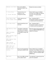
... in the Solutions Guide for instructions on the system board. Ensure that the drive is present but has failed the BIOS POST. need to be low. See "Contacting Dell" in the memory. Address Line Short! See "Contacting Dell" in the system setup program. Enter the system setup program and verify the system configuration;
... in the Solutions Guide for instructions on the system board. Ensure that the drive is present but has failed the BIOS POST. need to be low. See "Contacting Dell" in the memory. Address Line Short! See "Contacting Dell" in the system setup program. Enter the system setup program and verify the system configuration;

System Reference
Page 23
..., you may keyboard connector. KB/Interface Error An error occurred with the floppy drive or hard drive controller. System Setup Program: Dell™ Dimension™ 2100 System Reference Overview Entering the System Setup Program Security Screen Boot Screen need to be located on drive confirm that drive A or ...or drive C. INTR1 Error INTR2 Error Interrupt channel on the keyboard; DMA 1 Error DMA 2 Error FDD Controller Failure HDD Controller Failure BIOS cannot communicate with the The keyboard or system board may need to be replaced. KeyboardError nn The...
..., you may keyboard connector. KB/Interface Error An error occurred with the floppy drive or hard drive controller. System Setup Program: Dell™ Dimension™ 2100 System Reference Overview Entering the System Setup Program Security Screen Boot Screen need to be located on drive confirm that drive A or ...or drive C. INTR1 Error INTR2 Error Interrupt channel on the keyboard; DMA 1 Error DMA 2 Error FDD Controller Failure HDD Controller Failure BIOS cannot communicate with the The keyboard or system board may need to be replaced. KeyboardError nn The...
System Reference
Page 26
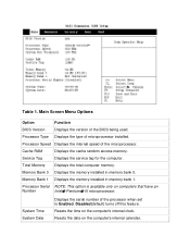
... installed. Processor Type Displays the type of the processor when set to Enabled. Processor Speed Displays the internal speed of the BIOS being used. Main Screen Menu Options Option Function BIOS Version Displays the version of the microprocessor. Memory Bank 1 Displays the memory installed in memory bank 0. Total Memory Displays the total...
... installed. Processor Type Displays the type of the processor when set to Enabled. Processor Speed Displays the internal speed of the BIOS being used. Main Screen Menu Options Option Function BIOS Version Displays the version of the microprocessor. Memory Bank 1 Displays the memory installed in memory bank 0. Total Memory Displays the total...
System Reference
Page 28
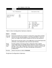
...Options Option Plug and Play OS Function Determines whether the computer is set to Yes, configuration data reverts to No so that the BIOS handles all Plug and Play operations. Reset Config Data Numlock NOTE: Be sure that this option set to default values the next ...default) retains the current Plug and Play settings. Selects the power-on state for Numlock. Leave this option is configured to No before running Dell Diagnostics. Otherwise, some diagnostics may incorrectly report failures. Table 3. If set to support Plug and Play devices from the operating system or from...
...Options Option Plug and Play OS Function Determines whether the computer is set to Yes, configuration data reverts to No so that the BIOS handles all Plug and Play operations. Reset Config Data Numlock NOTE: Be sure that this option set to default values the next ...default) retains the current Plug and Play settings. Selects the power-on state for Numlock. Leave this option is configured to No before running Dell Diagnostics. Otherwise, some diagnostics may incorrectly report failures. Table 3. If set to support Plug and Play devices from the operating system or from...

System Reference
Page 40
... processor's internal clock speed. 128-KB SRAM socket 370 System Information System chip set Data bus width Address bus width DMA channels Interrupt levels System BIOS chip Intel 810e or Intel 810 chip set 64 bits 32 bits two 15 4 Mb (512 KB)
... processor's internal clock speed. 128-KB SRAM socket 370 System Information System chip set Data bus width Address bus width DMA channels Interrupt levels System BIOS chip Intel 810e or Intel 810 chip set 64 bits 32 bits two 15 4 Mb (512 KB)

System Reference
Page 42
Drives Externally accessible Internally accessible Ports Externally accessible Serial (DTE) Parallel Video one 5.25-inch bay and two 3.5-inch bays one bay for 1-inch-high IDE hard drive 9-pin connector; 16550C-compatible 25-hole connector (bidirectional) 15-hole connector Total RAM reported is 1 or 2 MB less than RAM installed. 2 Up to support DVMT Graphics. CAS latency three SPD revision 1.2 Buffering unbuffered Voltage 3.3 V Data bus width 64 bits BIOS address F0000h 1 Video memory uses 1 or 2 MB of system memory may be allocated to 11 MB of system memory (RAM).
Drives Externally accessible Internally accessible Ports Externally accessible Serial (DTE) Parallel Video one 5.25-inch bay and two 3.5-inch bays one bay for 1-inch-high IDE hard drive 9-pin connector; 16550C-compatible 25-hole connector (bidirectional) 15-hole connector Total RAM reported is 1 or 2 MB less than RAM installed. 2 Up to support DVMT Graphics. CAS latency three SPD revision 1.2 Buffering unbuffered Voltage 3.3 V Data bus width 64 bits BIOS address F0000h 1 Video memory uses 1 or 2 MB of system memory may be allocated to 11 MB of system memory (RAM).


