
System Information Guide
Page 3
...in this text: Dell, Latitude, DellWare, AccessDirect, DELL E COM logo are trademarks of text may be accompanied by an icon and printed in bold type or in this document is strictly forbidden. Dell Computer Corporation disclaims any manner whatsoever without notice. © 2000 Dell Computer Corporation. Notes,... used as follows: NOTE: A NOTE indicates important information that helps you how to change without the written permission of Dell Computer Corporation is subject to avoid the problem. These blocks are notes, notices, and cautions, and they are registered trademarks of...
...in this text: Dell, Latitude, DellWare, AccessDirect, DELL E COM logo are trademarks of text may be accompanied by an icon and printed in bold type or in this document is strictly forbidden. Dell Computer Corporation disclaims any manner whatsoever without notice. © 2000 Dell Computer Corporation. Notes,... used as follows: NOTE: A NOTE indicates important information that helps you how to change without the written permission of Dell Computer Corporation is subject to avoid the problem. These blocks are notes, notices, and cautions, and they are registered trademarks of...
System Information Guide
Page 4
The User's Guide is not available in your Dell computer. support.dell.com Dell Latitude System Information 1-1 (Rev. 11/3/98) FILE LOCATION: D:\Eri_DProject\Dell\Temp\413CU0s\413CUeb0.fm Dell™ Latitude™ System Information Your Dell Latitude portable computer accessories box includes a reduced set of computer features, instructions on installing and configuring drivers and utilities, information on the System Setup...
The User's Guide is not available in your Dell computer. support.dell.com Dell Latitude System Information 1-1 (Rev. 11/3/98) FILE LOCATION: D:\Eri_DProject\Dell\Temp\413CU0s\413CUeb0.fm Dell™ Latitude™ System Information Your Dell Latitude portable computer accessories box includes a reduced set of computer features, instructions on installing and configuring drivers and utilities, information on the System Setup...
System Information Guide
Page 5
... the total ampere rating of the products plugged into the extension cable does not exceed the ampere rating of the extension cable. 1-2 Dell Latitude System Information The resulting excessive current flow can cause extremely high temperatures and may result in your computer. Doing so can cause fire.... Safety Instructions Use the following safety guidelines: • Do not allow your Latitude portable computer to charge the battery. Use of other types may present a risk of fire. • Use only Dell battery modules that the cable is not located where it to run the computer ...
... the total ampere rating of the products plugged into the extension cable does not exceed the ampere rating of the extension cable. 1-2 Dell Latitude System Information The resulting excessive current flow can cause extremely high temperatures and may result in your computer. Doing so can cause fire.... Safety Instructions Use the following safety guidelines: • Do not allow your Latitude portable computer to charge the battery. Use of other types may present a risk of fire. • Use only Dell battery modules that the cable is not located where it to run the computer ...
System Information Guide
Page 6
... shock, do not connect or disconnect any static electricity that might harm internal components. (Rev. 11/3/98) FILE LOCATION: D:\Eri_DProject\Dell\Temp\413CU0s\413CUeb0.fm • To remove power from the computer, turn it . • Disconnect any peripherals attached to your computer... waste disposal agency for personal injury or shock. • If the computer is when you are installing memory modules. support.dell.com Dell Latitude System Information 1-3 They may become very warm during normal operation. Preparing to dissipate any cables or perform maintenance or reconfiguration of...
... shock, do not connect or disconnect any static electricity that might harm internal components. (Rev. 11/3/98) FILE LOCATION: D:\Eri_DProject\Dell\Temp\413CU0s\413CUeb0.fm • To remove power from the computer, turn it . • Disconnect any peripherals attached to your computer... waste disposal agency for personal injury or shock. • If the computer is when you are installing memory modules. support.dell.com Dell Latitude System Information 1-3 They may become very warm during normal operation. Preparing to dissipate any cables or perform maintenance or reconfiguration of...
System Information Guide
Page 7
...Guidelines • Shielded signal cables: Using shielded cables ensures that endangers the functioning of your online User's Guide. 1-4 Dell Latitude System Information You can harm electronic components inside your authority to comply with applicable regulations regarding your computer can order a... unpainted metal surface on the computer's I/O panel. • Electromagnetic Interference (EMI) is available from Dell Computer Corporation. Additional regulatory information regarding EMI. If you prefer, you maintain the appropriate EMC classification for the intended environment.
...Guidelines • Shielded signal cables: Using shielded cables ensures that endangers the functioning of your online User's Guide. 1-4 Dell Latitude System Information You can harm electronic components inside your authority to comply with applicable regulations regarding your computer can order a... unpainted metal surface on the computer's I/O panel. • Electromagnetic Interference (EMI) is available from Dell Computer Corporation. Additional regulatory information regarding EMI. If you prefer, you maintain the appropriate EMC classification for the intended environment.
System Information Guide
Page 8
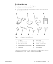
Set aside the contents of your computer, perform the following steps: 1. (Rev. 11/3/98) FILE LOCATION: D:\Eri_DProject\Dell\Temp\413CU0s\413CUeb0.fm Getting Started To set up your computer. Unpack the accessories box (see Figure 1-1). 2. support.dell.com Dell Latitude System Information 1-5 Figure 1-1. Accessories Box Contents 1 AC adapter 2 CD-ROM drive module 3 Floppy-disk drive...
Set aside the contents of your computer, perform the following steps: 1. (Rev. 11/3/98) FILE LOCATION: D:\Eri_DProject\Dell\Temp\413CU0s\413CUeb0.fm Getting Started To set up your computer. Unpack the accessories box (see Figure 1-1). 2. support.dell.com Dell Latitude System Information 1-5 Figure 1-1. Accessories Box Contents 1 AC adapter 2 CD-ROM drive module 3 Floppy-disk drive...
System Information Guide
Page 9
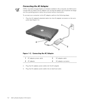
... connect your computer to the AC adapter, perform the following steps: 1. Figure 1-2. Plug the AC adapter power cable into an electrical outlet. 1-6 Dell Latitude System Information Plug the AC adapter power cable into the AC adapter. 3. Connecting the AC Adapter 1 AC adapter power cable 2 AC adapter 3... AC adapter cable 4 AC adapter connector 2. (Rev. 11/3/98) FILE LOCATION: D:\Eri_DProject\Dell\Temp\413CU0s\413CUeb0.fm Connecting the AC Adapter NOTE: A partially charged battery is already installed in the computer, but...
... connect your computer to the AC adapter, perform the following steps: 1. Figure 1-2. Plug the AC adapter power cable into an electrical outlet. 1-6 Dell Latitude System Information Plug the AC adapter power cable into the AC adapter. 3. Connecting the AC Adapter 1 AC adapter power cable 2 AC adapter 3... AC adapter cable 4 AC adapter connector 2. (Rev. 11/3/98) FILE LOCATION: D:\Eri_DProject\Dell\Temp\413CU0s\413CUeb0.fm Connecting the AC Adapter NOTE: A partially charged battery is already installed in the computer, but...
System Information Guide
Page 10
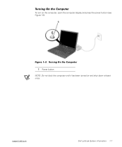
Turning On the Computer 1 Power button NOTE: Do not dock the computer until it has been turned on the computer, open the computer display and press the power button (see Figure 1-3). support.dell.com Dell Latitude System Information 1-7 (Rev. 11/3/98) FILE LOCATION: D:\Eri_DProject\Dell\Temp\413CU0s\413CUeb0.fm Turning On the Computer To turn on and shut down at least once. Figure 1-3.
Turning On the Computer 1 Power button NOTE: Do not dock the computer until it has been turned on the computer, open the computer display and press the power button (see Figure 1-3). support.dell.com Dell Latitude System Information 1-7 (Rev. 11/3/98) FILE LOCATION: D:\Eri_DProject\Dell\Temp\413CU0s\413CUeb0.fm Turning On the Computer To turn on and shut down at least once. Figure 1-3.
System Information Guide
Page 11
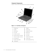
Front View of the computer's components. Figure 1-4. (Rev. 11/3/98) FILE LOCATION: D:\Eri_DProject\Dell\Temp\413CU0s\413CUeb0.fm Computer Components Figures 1-4 and 1-5 show the locations of Computer 1 Display latch 11 Speaker 2 Display 12 Modular bay 3 Microphone 13 Display latch ... 15 Touch pad 6 Optional network connector 16 Track stick 7 Optional modem connector 17 Keyboard status lights 8 Audio jacks (2) 18 Power button 9 System status lights 19 Dell AccessDirect™ key 10 Infrared port 1-8 Dell Latitude System Information
Front View of the computer's components. Figure 1-4. (Rev. 11/3/98) FILE LOCATION: D:\Eri_DProject\Dell\Temp\413CU0s\413CUeb0.fm Computer Components Figures 1-4 and 1-5 show the locations of Computer 1 Display latch 11 Speaker 2 Display 12 Modular bay 3 Microphone 13 Display latch ... 15 Touch pad 6 Optional network connector 16 Track stick 7 Optional modem connector 17 Keyboard status lights 8 Audio jacks (2) 18 Power button 9 System status lights 19 Dell AccessDirect™ key 10 Infrared port 1-8 Dell Latitude System Information
System Information Guide
Page 12
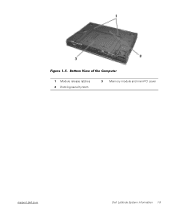
Bottom View of the Computer 1 Module release latches 2 Docking security latch 3 Memory module and mini-PCI cover support.dell.com Dell Latitude System Information 1-9 (Rev. 11/3/98) FILE LOCATION: D:\Eri_DProject\Dell\Temp\413CU0s\413CUeb0.fm Figure 1-5.
Bottom View of the Computer 1 Module release latches 2 Docking security latch 3 Memory module and mini-PCI cover support.dell.com Dell Latitude System Information 1-9 (Rev. 11/3/98) FILE LOCATION: D:\Eri_DProject\Dell\Temp\413CU0s\413CUeb0.fm Figure 1-5.
System Information Guide
Page 13
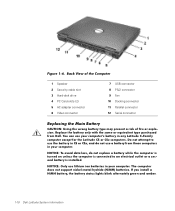
... you install a NiMH battery, the battery status lights blink alternately green and amber. 1-10 Dell Latitude System Information NOTICE: To avoid data loss, do not use the battery in CS or CSx, and do not replace a battery while the computer is ... wrong battery type may present a risk of fire or explosion. You can use lithium ion batteries in any Latitude C-Family computer except for the Latitude CS or CSx computers. (Rev. 11/3/98) FILE LOCATION: D:\Eri_DProject\Dell\Temp\413CU0s\413CUeb0.fm Figure 1-6. NOTICE: Only use your computer. Replace the battery only with the same...
... you install a NiMH battery, the battery status lights blink alternately green and amber. 1-10 Dell Latitude System Information NOTICE: To avoid data loss, do not use the battery in CS or CSx, and do not replace a battery while the computer is ... wrong battery type may present a risk of fire or explosion. You can use lithium ion batteries in any Latitude C-Family computer except for the Latitude CS or CSx computers. (Rev. 11/3/98) FILE LOCATION: D:\Eri_DProject\Dell\Temp\413CU0s\413CUeb0.fm Figure 1-6. NOTICE: Only use your computer. Replace the battery only with the same...
System Information Guide
Page 14
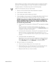
...• For Windows 95, Windows 98, or Windows NT, use suspend-to complete the battery replacement. (Rev. 11/3/98) FILE LOCATION: D:\Eri_DProject\Dell\Temp\413CU0s\413CUeb0.fm Before installing a new battery, check the battery's charge, by pressing (or on a French keyboard). After 4 minutes, the .... 3. Depending on how you have up to 4 minutes to -disk mode. Remove the battery from the battery bay: a. c. support.dell.com Dell Latitude System Information 1-11 If the modular bay contains a battery, go to -disk mode by pressing the battery test button. Close the computer display...
...• For Windows 95, Windows 98, or Windows NT, use suspend-to complete the battery replacement. (Rev. 11/3/98) FILE LOCATION: D:\Eri_DProject\Dell\Temp\413CU0s\413CUeb0.fm Before installing a new battery, check the battery's charge, by pressing (or on a French keyboard). After 4 minutes, the .... 3. Depending on how you have up to 4 minutes to -disk mode. Remove the battery from the battery bay: a. c. support.dell.com Dell Latitude System Information 1-11 If the modular bay contains a battery, go to -disk mode by pressing the battery test button. Close the computer display...
System Information Guide
Page 15
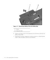
Removing a Battery From the Battery Bay 1 Battery 2 Battery bay latch 6. (Rev. 11/3/98) FILE LOCATION: D:\Eri_DProject\Dell\Temp\413CU0s\413CUeb0.fm Figure 1-7. Depending on the power management mode the computer is fully seated. 7. Slide the new battery firmly into the battery bay. You should hear a click when the battery is in, press the power button or open the display to resume normal operation. 1-12 Dell Latitude System Information
Removing a Battery From the Battery Bay 1 Battery 2 Battery bay latch 6. (Rev. 11/3/98) FILE LOCATION: D:\Eri_DProject\Dell\Temp\413CU0s\413CUeb0.fm Figure 1-7. Depending on the power management mode the computer is fully seated. 7. Slide the new battery firmly into the battery bay. You should hear a click when the battery is in, press the power button or open the display to resume normal operation. 1-12 Dell Latitude System Information
System Information Guide
Page 16
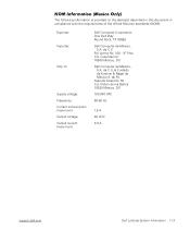
...: Frequency: Current consumption (maximum): Output voltage Output current (maximum) Dell Computer Corporation One Dell Way Round Rock, TX 78682 Dell Computer de México, S.A. de C.V. (Rev. 11/3/98) FILE LOCATION: D:\Eri_DProject\Dell\Temp\413CU0s\413CUeb0.fm NOM Information (Mexico Only) The following information ...is provided on de los Baños 15520 México, D.F. 100-240 VAC 60-50 Hz 1.5 A 20 VDC 3.5 A support.dell.com Dell Latitude System Information 1-13 al Cuidado de Kuehne & Nagel de México S. de R.I. Cuauhtemoc 16500 México, D.F. Rio Lerma No. 302...
...: Frequency: Current consumption (maximum): Output voltage Output current (maximum) Dell Computer Corporation One Dell Way Round Rock, TX 78682 Dell Computer de México, S.A. de C.V. (Rev. 11/3/98) FILE LOCATION: D:\Eri_DProject\Dell\Temp\413CU0s\413CUeb0.fm NOM Information (Mexico Only) The following information ...is provided on de los Baños 15520 México, D.F. 100-240 VAC 60-50 Hz 1.5 A 20 VDC 3.5 A support.dell.com Dell Latitude System Information 1-13 al Cuidado de Kuehne & Nagel de México S. de R.I. Cuauhtemoc 16500 México, D.F. Rio Lerma No. 302...
System Information Guide
Page 18
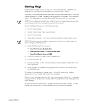
... Turn the computer on the computer. 4. Insert the Dell ResourceCD into the CD-ROM drive. 7. Then restart your needs. After the diagnostics loads, the Diagnostics Menu appears. support.dell.com Dell Latitude System Information 1-15 For information on the ResourceCD that corresponds... to restore it . Undock the computer if you call Dell's technical support because the diagnostic tests provide information ...
... Turn the computer on the computer. 4. Insert the Dell ResourceCD into the CD-ROM drive. 7. Then restart your needs. After the diagnostics loads, the Diagnostics Menu appears. support.dell.com Dell Latitude System Information 1-15 For information on the ResourceCD that corresponds... to restore it . Undock the computer if you call Dell's technical support because the diagnostic tests provide information ...

Service Manual
Page 1
Dell Latitude C600/C500 Series Service Manual Dell™ Latitude™ C600/C500 Series Service Manual Before You Begin Preparing to avoid the problem. file:///F|/Service%20Manuals/Dell/Latitude/c500-600/index.htm (1 of your computer. NOTICE: A NOTICE indicates either potential damage to hardware or loss of data and tells you how to Work ...
Dell Latitude C600/C500 Series Service Manual Dell™ Latitude™ C600/C500 Series Service Manual Before You Begin Preparing to avoid the problem. file:///F|/Service%20Manuals/Dell/Latitude/c500-600/index.htm (1 of your computer. NOTICE: A NOTICE indicates either potential damage to hardware or loss of data and tells you how to Work ...

Service Manual
Page 2
... hibernate mode. Turn off and not in progress and close all attached devices. Before You Begin : Dell Latitude C600/C500 Series Service Manual Back to Contents Page Before You Begin Dell™ Latitude™ C600/C500 Series Service Manual Preparing to Work Inside the Computer Recommended Tools Screw Identification Preparing to Work Inside ... your warranty. If you begin .htm (1 of 6) [2/28/2004 7:53:27 AM] Disconnect the computer from the electrical outlet. 6. file:///F|/Service%20Manuals/Dell/Latitude/c500-600/begin working inside the computer. 1. Save any attached devices.
... hibernate mode. Turn off and not in progress and close all attached devices. Before You Begin : Dell Latitude C600/C500 Series Service Manual Back to Contents Page Before You Begin Dell™ Latitude™ C600/C500 Series Service Manual Preparing to Work Inside the Computer Recommended Tools Screw Identification Preparing to Work Inside ... your warranty. If you begin .htm (1 of 6) [2/28/2004 7:53:27 AM] Disconnect the computer from the electrical outlet. 6. file:///F|/Service%20Manuals/Dell/Latitude/c500-600/begin working inside the computer. 1. Save any attached devices.

Service Manual
Page 3
...q Flash BIOS update program diskette or CD (required only when upgrading the microprocessor or replacing the reserve battery) System Orientation file:///F|/Service%20Manuals/Dell/Latitude/c500-600/begin.htm (2 of 6) [2/28/2004 7:53:27 AM] Close the display and turn the computer upside down on a card. ...Before You Begin : Dell Latitude C600/C500 Series Service Manual 7. Remove any installed device in the modular bay. 12. Recommended Tools The procedures in use a wrist grounding strap or...
...q Flash BIOS update program diskette or CD (required only when upgrading the microprocessor or replacing the reserve battery) System Orientation file:///F|/Service%20Manuals/Dell/Latitude/c500-600/begin.htm (2 of 6) [2/28/2004 7:53:27 AM] Close the display and turn the computer upside down on a card. ...Before You Begin : Dell Latitude C600/C500 Series Service Manual 7. Remove any installed device in the modular bay. 12. Recommended Tools The procedures in use a wrist grounding strap or...

Service Manual
Page 4
The placemat provides the number of the component screws. Before You Begin : Dell Latitude C600/C500 Series Service Manual Screw Identification When you are removing and replacing components, photocopy the placemat as a tool to lay out and keep track of screws and the sizes. Screw Identification file:///F|/Service%20Manuals/Dell/Latitude/c500-600/begin.htm (3 of 6) [2/28/2004 7:53:27 AM]
The placemat provides the number of the component screws. Before You Begin : Dell Latitude C600/C500 Series Service Manual Screw Identification When you are removing and replacing components, photocopy the placemat as a tool to lay out and keep track of screws and the sizes. Screw Identification file:///F|/Service%20Manuals/Dell/Latitude/c500-600/begin.htm (3 of 6) [2/28/2004 7:53:27 AM]

Service Manual
Page 5
Screw Placement Hard Drive Door Security: (1 each) Keyboard to Bottom Case Assembly: (5 each) Display Assembly Bezel: (6 each) Display Assembly Hinge Bracket to Bottom Case Assembly: (5 each) Rubber Screw Covers (6 each) file:///F|/Service%20Manuals/Dell/Latitude/c500-600/begin.htm (4 of the correct diameter and length. Make sure that the screw is properly aligned with its corresponding hole, and avoid overtightening. Before You Begin : Dell Latitude C600/C500 Series Service Manual NOTICE: When reinstalling a screw, you must use a screw of 6) [2/28/2004 7:53:27 AM]
Screw Placement Hard Drive Door Security: (1 each) Keyboard to Bottom Case Assembly: (5 each) Display Assembly Bezel: (6 each) Display Assembly Hinge Bracket to Bottom Case Assembly: (5 each) Rubber Screw Covers (6 each) file:///F|/Service%20Manuals/Dell/Latitude/c500-600/begin.htm (4 of the correct diameter and length. Make sure that the screw is properly aligned with its corresponding hole, and avoid overtightening. Before You Begin : Dell Latitude C600/C500 Series Service Manual NOTICE: When reinstalling a screw, you must use a screw of 6) [2/28/2004 7:53:27 AM]


