
Product Manual
Page 3
xStack® DGS-3120 Series Managed Switch Web UI Reference Guide Table of Contents Intended Readers...1 Typographical Conventions...1 Notes, Notices and Cautions...1 Chapter 1 Web-based Switch Configuration 2 Introduction ...2 Login ... Settings...10 PoE Port Settings ...11 Serial Port Settings ...13 Warning Temperature Settings ...13 System Log configuration...14 System Log Settings...14 System Log Server Settings ...15 System Log...16 System Log & Trap Settings...16 System Severity Settings...17 Time Range Settings...18 Port Group Settings (EI Mode Only) ...18 Time Settings...
xStack® DGS-3120 Series Managed Switch Web UI Reference Guide Table of Contents Intended Readers...1 Typographical Conventions...1 Notes, Notices and Cautions...1 Chapter 1 Web-based Switch Configuration 2 Introduction ...2 Login ... Settings...10 PoE Port Settings ...11 Serial Port Settings ...13 Warning Temperature Settings ...13 System Log configuration...14 System Log Settings...14 System Log Server Settings ...15 System Log...16 System Log & Trap Settings...16 System Severity Settings...17 Time Range Settings...18 Port Group Settings (EI Mode Only) ...18 Time Settings...
Product Manual
Page 13
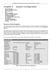
... link. Figure 2-1 Device Information window (SI Mode Only) 5 xStack® DGS-3120 Series Managed Switch Web UI Reference Guide Chapter 2 System Configuration Device Information System Information Settings Port Configuration PoE Serial Port Settings Warning Temperature Settings System Log configuration Time Range Settings Port Group Settings (EI Mode Only) Time Settings User Accounts Settings Command Logging...
... link. Figure 2-1 Device Information window (SI Mode Only) 5 xStack® DGS-3120 Series Managed Switch Web UI Reference Guide Chapter 2 System Configuration Device Information System Information Settings Port Configuration PoE Serial Port Settings Warning Temperature Settings System Log configuration Time Range Settings Port Group Settings (EI Mode Only) Time Settings User Accounts Settings Command Logging...

Product Manual
Page 18
...All ports can supply about 48 VDC power to 30W. Ports 1-24 can support PoE up to Powered Devices (PDs) over Category 5 or Category 3 UTP Ethernet cables. The Switches work with all D-Link 802.3af capable devices. Based on 802.3af/at PDs receive power according to... power available to PD 0 15.4W 1 4.0W 2 7.0W 3 15.4W 4 15.4W PSE provides power according to implement changes made. PoE The DGS-3120-24PC and DGS-3120-48PC switches support Power over pins 1, 2, 3 and 6. Other ports will remain active. The default is 1536 bytes. The Switch includes the following window...
...All ports can supply about 48 VDC power to 30W. Ports 1-24 can support PoE up to Powered Devices (PDs) over Category 5 or Category 3 UTP Ethernet cables. The Switches work with all D-Link 802.3af capable devices. Based on 802.3af/at PDs receive power according to... power available to PD 0 15.4W 1 4.0W 2 7.0W 3 15.4W 4 15.4W PSE provides power according to implement changes made. PoE The DGS-3120-24PC and DGS-3120-48PC switches support Power over pins 1, 2, 3 and 6. Other ports will remain active. The default is 1536 bytes. The Switch includes the following window...

Product Manual
Page 19
The user may configure a Power Limit between 37W and 740W for the DGS-3120-24PC and DGS-3120-48PC. The default setting is 19W. If Power Disconnection Method is set to Deny Next Port, the system cannot utilize out of its priority. Power Limit...power capacity. The maximum unused watt is 740W. Click Apply to select all units. xStack® DGS-3120 Series Managed Switch Web UI Reference Guide Figure 2-8 PoE System Settings window The following window, click System Configuration > PoE > PoE Port Settings, as to allow the high-priority and critical priority ports to power up. Tick ...
The user may configure a Power Limit between 37W and 740W for the DGS-3120-24PC and DGS-3120-48PC. The default setting is 19W. If Power Disconnection Method is set to Deny Next Port, the system cannot utilize out of its priority. Power Limit...power capacity. The maximum unused watt is 740W. Click Apply to select all units. xStack® DGS-3120 Series Managed Switch Web UI Reference Guide Figure 2-8 PoE System Settings window The following window, click System Configuration > PoE > PoE Port Settings, as to allow the high-priority and critical priority ports to power up. Tick ...
Product Manual
Page 20
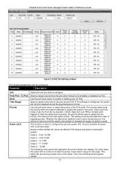
xStack® DGS-3120 Series Managed Switch Web UI Reference Guide Figure 2-9 PoE Port Settings window The following parameters can be configured: Parameter Description Unit From Port / To Port State Time Range Priority Power Limit Select the unit you wish to enable or disable ports for PoE. Use the pull-down... lower port ID has higher priority. If Time Range is configured, the power can be enabled or disabled for PoE. For each class, the power limit is set as POE. Select a range of priority, the port ID will be used to manage the supply of priority that class....
xStack® DGS-3120 Series Managed Switch Web UI Reference Guide Figure 2-9 PoE Port Settings window The following parameters can be configured: Parameter Description Unit From Port / To Port State Time Range Priority Power Limit Select the unit you wish to enable or disable ports for PoE. Use the pull-down... lower port ID has higher priority. If Time Range is configured, the power can be enabled or disabled for PoE. For each class, the power limit is set as POE. Select a range of priority, the port ID will be used to manage the supply of priority that class....
Product Manual
Page 21
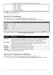
... bits used for the serial port connection. The default setting is displayed in the table in the bottom half of time, as defined. xStack® DGS-3120 Series Managed Switch Web UI Reference Guide Class 0 - 16200mW Class 1 - 4200mW Class 2 - 7400mW Class 3 - 16200mW User Define - 35000mW Click ...Apply to implement changes made . The port status of all PoE configured ports is 10 minutes. For a connection to the Switch using the console port, the baud rate must be configured are four possible baud rates...
... bits used for the serial port connection. The default setting is displayed in the table in the bottom half of time, as defined. xStack® DGS-3120 Series Managed Switch Web UI Reference Guide Class 0 - 16200mW Class 1 - 4200mW Class 2 - 7400mW Class 3 - 16200mW User Define - 35000mW Click ...Apply to implement changes made . The port status of all PoE configured ports is 10 minutes. For a connection to the Switch using the console port, the baud rate must be configured are four possible baud rates...

