
Installation Guide
Page 60
... to be allowed to power lines, remove jewelry (including rings, necklaces, and watches). Preparing for Installation Chapter 2 Installing and Starting Up the Switch Preparing for Installation Warnings These warnings are translated into several languages in Appendix C, "Translated Safety Warnings." If the chassis falls, it serves as ...defined by service personnel only as the main disconnecting device. Warning This equipment is connected to install or replace this equipment. Statement 66 Catalyst 3500 Series XL Hardware Installation Guide 2-2 78-6456-04
... to be allowed to power lines, remove jewelry (including rings, necklaces, and watches). Preparing for Installation Chapter 2 Installing and Starting Up the Switch Preparing for Installation Warnings These warnings are translated into several languages in Appendix C, "Translated Safety Warnings." If the chassis falls, it serves as ...defined by service personnel only as the main disconnecting device. Warning This equipment is connected to install or replace this equipment. Statement 66 Catalyst 3500 Series XL Hardware Installation Guide 2-2 78-6456-04
Installation Guide
Page 64
The seller or buyer should be replaced with a residential-use . Statement 191 Korea Warning This is a Class A Device and is registered for EMC requirements for industrial use type. Preparing for Installation Japan Chapter 2 Installing and Starting Up the Switch Warning This is a Class A product... based on the standard of this. When such trouble occurs, the user may arise. Statement 294 Catalyst 3500 Series XL Hardware Installation Guide 2-6 78-6456-04 If ...
The seller or buyer should be replaced with a residential-use . Statement 191 Korea Warning This is a Class A Device and is registered for EMC requirements for industrial use type. Preparing for Installation Japan Chapter 2 Installing and Starting Up the Switch Warning This is a Class A product... based on the standard of this. When such trouble occurs, the user may arise. Statement 294 Catalyst 3500 Series XL Hardware Installation Guide 2-6 78-6456-04 If ...
Installation Guide
Page 95
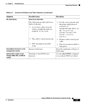
...3 Troubleshooting Diagnosing Problems Table 3-2 Common Problems and Their Solutions (continued) Symptom No connectivity. Unreadable characters on the Catalyst 3508, 3512, or 3524 XL switch. Use the show POST command to 9600 baud. System LED is wired incorrectly. • STP checking for LED ...to turn green. Reset the emulation software to see the "Crossover and Straight-Through Cable Pinouts" section on page B-4. • Replace with a tested ...
...3 Troubleshooting Diagnosing Problems Table 3-2 Common Problems and Their Solutions (continued) Symptom No connectivity. Unreadable characters on the Catalyst 3508, 3512, or 3524 XL switch. Use the show POST command to 9600 baud. System LED is wired incorrectly. • STP checking for LED ...to turn green. Reset the emulation software to see the "Crossover and Straight-Through Cable Pinouts" section on page B-4. • Replace with a tested ...

Installation Guide
Page 96
...exists. Replace the switch at your convenience. • Use the show env command to a Catalyst 3524-PWR XL switch. Catalyst 3500 Series XL Hardware Installation Guide 3-6 78-6456-04 Possible Cause • Internal fan fault detected. • Switch is amber on Improper cabling. The Catalyst 3524-PWR XL switch can... operate normally with one failed fan. Make sure the switch is connected to the LAN-to power on the Catalyst 3524-PWR XL. Cisco IP Phone fails to -phone jack on...
...exists. Replace the switch at your convenience. • Use the show env command to a Catalyst 3524-PWR XL switch. Catalyst 3500 Series XL Hardware Installation Guide 3-6 78-6456-04 Possible Cause • Internal fan fault detected. • Switch is amber on Improper cabling. The Catalyst 3524-PWR XL switch can... operate normally with one failed fan. Make sure the switch is connected to the LAN-to power on the Catalyst 3524-PWR XL. Cisco IP Phone fails to -phone jack on...