
Installation Guide
Page 2
...any interference to part 15 of Class B devices: The equipment described in this equipment in a residential installation. All rights reserved. CISCO AND THE ABOVE-NAMED SUPPLIERS DISCLAIM ALL WARRANTIES, EXPRESSED OR IMPLIED, INCLUDING, WITHOUT LIMITATION, THOSE OF MERCHANTABILITY, FITNESS FOR A ... FULL RESPONSIBILITY FOR THEIR APPLICATION OF ANY PRODUCTS. This equipment generates, uses, and can determine whether your own expense. THE SPECIFICATIONS AND INFORMATION REGARDING THE PRODUCTS IN THIS MANUAL ARE SUBJECT TO CHANGE WITHOUT NOTICE. The following measures: • Turn the ...
...any interference to part 15 of Class B devices: The equipment described in this equipment in a residential installation. All rights reserved. CISCO AND THE ABOVE-NAMED SUPPLIERS DISCLAIM ALL WARRANTIES, EXPRESSED OR IMPLIED, INCLUDING, WITHOUT LIMITATION, THOSE OF MERCHANTABILITY, FITNESS FOR A ... FULL RESPONSIBILITY FOR THEIR APPLICATION OF ANY PRODUCTS. This equipment generates, uses, and can determine whether your own expense. THE SPECIFICATIONS AND INFORMATION REGARDING THE PRODUCTS IN THIS MANUAL ARE SUBJECT TO CHANGE WITHOUT NOTICE. The following measures: • Turn the ...

Installation Guide
Page 8
... B-1 1000BaseX Ports B-2 Gigastack Port B-3 Console Port B-3 Cable and Adapter Specifications B-4 Crossover and Straight-Through Cable Pinouts B-4 Rollover Cable and Adapter Pinouts B-5 Identifying a Rollover Cable B-5 Connecting to a PC B-6 Connecting to a Terminal B-7 Translated Safety Warnings C-1 Attaching the Cisco RPS (model PWR600-AC-RPS) C-2 Attaching the Cisco RPS (model PWR300-AC-RPS-N1) C-4 Service Personnel Warning...
... B-1 1000BaseX Ports B-2 Gigastack Port B-3 Console Port B-3 Cable and Adapter Specifications B-4 Crossover and Straight-Through Cable Pinouts B-4 Rollover Cable and Adapter Pinouts B-5 Identifying a Rollover Cable B-5 Connecting to a PC B-6 Connecting to a Terminal B-7 Translated Safety Warnings C-1 Attaching the Cisco RPS (model PWR600-AC-RPS) C-2 Attaching the Cisco RPS (model PWR300-AC-RPS-N1) C-4 Service Personnel Warning...

Installation Guide
Page 12
... standards they support, and the switch LEDs. Appendix A, "Technical Specifications," lists the physical and environmental specifications for installing a switch on a rack, wall, table, or shelf. Catalyst 3500 Series XL Hardware Installation Guide xii 78-6456-04 It also describes how to set up the switch initial configuration. Examples of how the switch could be used to connect...
... standards they support, and the switch LEDs. Appendix A, "Technical Specifications," lists the physical and environmental specifications for installing a switch on a rack, wall, table, or shelf. Catalyst 3500 Series XL Hardware Installation Guide xii 78-6456-04 It also describes how to set up the switch initial configuration. Examples of how the switch could be used to connect...

Installation Guide
Page 25
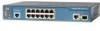
... specific to the Catalyst 3524-PWR XL switch is its ability to provide inline power to Cisco IP Phones. (Phone adapters are not required when connecting to the Catalyst 3524-PWR XL 10/100 switch ports.) Figure 1-1 shows the switch models in different network topologies Features The Catalyst 3500 series XL switches-also referred to as Catalyst 3500 XL switches-are...
... specific to the Catalyst 3524-PWR XL switch is its ability to provide inline power to Cisco IP Phones. (Phone adapters are not required when connecting to the Catalyst 3524-PWR XL 10/100 switch ports.) Figure 1-1 shows the switch models in different network topologies Features The Catalyst 3500 series XL switches-also referred to as Catalyst 3500 XL switches-are...

Installation Guide
Page 32
... full-duplex transmission, if the attached device supports it) and configures itself accordingly. Cisco IP Phones-connected to operate in Appendix B, "Connector and Cable Specifications." However, the Catalyst 3524-PWR XL 10/100 ports can: • Provide -48V DC power to switches or hubs, use Category 3 and 4 cables, but these features. Pinouts for autonegotiation...
... full-duplex transmission, if the attached device supports it) and configures itself accordingly. Cisco IP Phones-connected to operate in Appendix B, "Connector and Cable Specifications." However, the Catalyst 3524-PWR XL 10/100 ports can: • Provide -48V DC power to switches or hubs, use Category 3 and 4 cables, but these features. Pinouts for autonegotiation...

Installation Guide
Page 47
... the four DC output power modules. Cisco RPS Connector Specific Cisco RPS models support specific Catalyst 3500 XL switches: • Cisco RPS 600 (model PWR600-AC-RPS)-Supports the Catalyst 3512, 3524, 3548, and 3508 XL switches • Cisco RPS 300 (model PWR300-AC-RPS)-Supports the Catalyst 3524-PWR XL switch RPS Connector on the Cisco RPS 600, refer to the RPS...
... the four DC output power modules. Cisco RPS Connector Specific Cisco RPS models support specific Catalyst 3500 XL switches: • Cisco RPS 600 (model PWR600-AC-RPS)-Supports the Catalyst 3512, 3524, 3548, and 3508 XL switches • Cisco RPS 300 (model PWR300-AC-RPS)-Supports the Catalyst 3524-PWR XL switch RPS Connector on the Cisco RPS 600, refer to the RPS...

Installation Guide
Page 48
...source for these applications. 1-24 Catalyst 3500 Series XL Hardware Installation Guide 78-6456-04 For console port and adapter pinout information, see the "Cable and Adapter Specifications" section on page B-4. You use to the Cisco IOS Desktop Switching Software Configuration Guide and the online ...help for up of switches or an individual switch. Console Port You can order a kit (part number ...
...source for these applications. 1-24 Catalyst 3500 Series XL Hardware Installation Guide 78-6456-04 For console port and adapter pinout information, see the "Cable and Adapter Specifications" section on page B-4. You use to the Cisco IOS Desktop Switching Software Configuration Guide and the online ...help for up of switches or an individual switch. Console Port You can order a kit (part number ...

Installation Guide
Page 65
... GBIC ports, cable lengths from the switch to the connected devices are up to 1 meter. Class A equipment is designed for typical commercial establishments for Installation Warning This equipment is within the ranges listed in Appendix A, "Technical Specifications." 78-6456-04 Catalyst 3500 Series XL Hardware Installation Guide 2-7 For specific cable lengths, refer to the...
... GBIC ports, cable lengths from the switch to the connected devices are up to 1 meter. Class A equipment is designed for typical commercial establishments for Installation Warning This equipment is within the ranges listed in Appendix A, "Technical Specifications." 78-6456-04 Catalyst 3500 Series XL Hardware Installation Guide 2-7 For specific cable lengths, refer to the...

Installation Guide
Page 81
...the switch, you want to connect the switch console port to a terminal. Chapter 2 Installing and Starting Up the Switch Connecting a PC or Terminal to the Console Port For more information on page B-4. For console port and adapter pinout information, see the "Cable and Adapter Specifications" ... or terminal possible during the setup program. You can change the port baud rate. See the Cisco IOS Desktop Switching Software Configuration Guide for instructions. 78-6456-04 Catalyst 3500 Series XL Hardware Installation Guide 2-23 Connecting a PC or Terminal to the Console Port Use...
...the switch, you want to connect the switch console port to a terminal. Chapter 2 Installing and Starting Up the Switch Connecting a PC or Terminal to the Console Port For more information on page B-4. For console port and adapter pinout information, see the "Cable and Adapter Specifications" ... or terminal possible during the setup program. You can change the port baud rate. See the Cisco IOS Desktop Switching Software Configuration Guide for instructions. 78-6456-04 Catalyst 3500 Series XL Hardware Installation Guide 2-23 Connecting a PC or Terminal to the Console Port Use...

Installation Guide
Page 84
...Specifications" section on page B-4. You can order a kit (part number ACS-DSBUASYN=) containing that adapter from Cisco. Use the supplied rollover cable and DB-9 adapter to connect a PC to restart the setup program. Enter setup, and press Return to the switch console port. Enter the switch...IP netmask: ip_netmask Enter Y to specify a default gateway (router): Would you want to connect the switch console port to create an initial configuration for the switch, and press Return: 2-26 Catalyst 3500 Series XL Hardware Installation Guide 78-6456-04 Step 1 Step 2 Step 3 Step 4 Step...
...Specifications" section on page B-4. You can order a kit (part number ACS-DSBUASYN=) containing that adapter from Cisco. Use the supplied rollover cable and DB-9 adapter to connect a PC to restart the setup program. Enter setup, and press Return to the switch console port. Enter the switch...IP netmask: ip_netmask Enter Y to specify a default gateway (router): Would you want to connect the switch console port to create an initial configuration for the switch, and press Return: 2-26 Catalyst 3500 Series XL Hardware Installation Guide 78-6456-04 Step 1 Step 2 Step 3 Step 4 Step...

Installation Guide
Page 97
Table A-1 Technical Specifications for the Catalyst 3500 series XL switches. Table A-4 lists the regulatory agency approvals. A A P P E N D I X Technical Specifications 78-6456-04 Table A-1, Table A-2, and Table A-3, list the technical specifications for the Catalyst 3508G XL Switch Environmental Ranges Operating temperature Storage temperature Operating humidity Operating altitude Storage altitude Power Requirements AC input voltage ... @3A 82.2W 280 Btus per hour 12 lb (5.45 kg) 1.75 x 16 x 17.5 in. (4.45 x 40.46 x 44.45 cm) Catalyst 3500 Series XL Hardware Installation Guide A-1
Table A-1 Technical Specifications for the Catalyst 3500 series XL switches. Table A-4 lists the regulatory agency approvals. A A P P E N D I X Technical Specifications 78-6456-04 Table A-1, Table A-2, and Table A-3, list the technical specifications for the Catalyst 3508G XL Switch Environmental Ranges Operating temperature Storage temperature Operating humidity Operating altitude Storage altitude Power Requirements AC input voltage ... @3A 82.2W 280 Btus per hour 12 lb (5.45 kg) 1.75 x 16 x 17.5 in. (4.45 x 40.46 x 44.45 cm) Catalyst 3500 Series XL Hardware Installation Guide A-1

Installation Guide
Page 98
Appendix A Technical Specifications Table A-2 Technical Specifications for the Catalyst 3512, 3524, and 3548 XL Switches Catalyst 3512 XL Catalyst 3524 XL Catalyst 3548 XL Environmental Ranges Operating temperature 32 to 113°F (0 to 45°C) 32 to 113°F (0 to 45°C) 32 to 113°F (0 to ....82 x 17.5 in. 1.73 x 15.34 x 17.5 in D x W) (4.45 x 30.02 x 44.45 cm) (4.45 x 30.02 x 44.45 cm) (4.39 x 39.0 x 44.45 cm) Catalyst 3500 Series XL Hardware Installation Guide A-2 78-6456-04
Appendix A Technical Specifications Table A-2 Technical Specifications for the Catalyst 3512, 3524, and 3548 XL Switches Catalyst 3512 XL Catalyst 3524 XL Catalyst 3548 XL Environmental Ranges Operating temperature 32 to 113°F (0 to 45°C) 32 to 113°F (0 to 45°C) 32 to 113°F (0 to ....82 x 17.5 in. 1.73 x 15.34 x 17.5 in D x W) (4.45 x 30.02 x 44.45 cm) (4.45 x 30.02 x 44.45 cm) (4.39 x 39.0 x 44.45 cm) Catalyst 3500 Series XL Hardware Installation Guide A-2 78-6456-04

Installation Guide
Page 99
The actual power consumption depends on the number of IP phones connected. 325W represents 24 IP phones connected. Table A-4 Catalyst 3500 Series XL Agency Approvals Safety EMC UL to UL 1950, Third Edition FCC Part 15 Class A c-UL to CAN/...65 kg) Dimensions (H x W x D) 1.75 x 11.82 x 17.5 in. (4.45 x 30.02 x 44.45 cm) 1. Appendix A Technical Specifications Table A-3 Technical Specifications for the Catalyst 3524-PWR XL Switch Environmental Ranges Operating temperature 32 to 113°F (0 to 45°C) Storage temperature -4 to 149°F (-10 to 65°C) Operating humidity...
The actual power consumption depends on the number of IP phones connected. 325W represents 24 IP phones connected. Table A-4 Catalyst 3500 Series XL Agency Approvals Safety EMC UL to UL 1950, Third Edition FCC Part 15 Class A c-UL to CAN/...65 kg) Dimensions (H x W x D) 1.75 x 11.82 x 17.5 in. (4.45 x 30.02 x 44.45 cm) 1. Appendix A Technical Specifications Table A-3 Technical Specifications for the Catalyst 3524-PWR XL Switch Environmental Ranges Operating temperature 32 to 113°F (0 to 45°C) Storage temperature -4 to 149°F (-10 to 65°C) Operating humidity...

Installation Guide
Page 100
Appendix A Technical Specifications Catalyst 3500 Series XL Hardware Installation Guide A-4 78-6456-04
Appendix A Technical Specifications Catalyst 3500 Series XL Hardware Installation Guide A-4 78-6456-04

Installation Guide
Page 101
...B-1 shows the pinout. When connecting the 10/100 ports to compatible workstations, servers, routers, and Cisco IP Phones, you use to connect the switch to other switches or repeaters, ensure that a straight-through cable and adapter can be attached to connect two ports ...Figure B-4 illustrates the crossover cable schematics.) Note Use a straight-through cable to the port. APPENDIX B Connector and Cable Specifications This appendix describes the Catalyst 3500 XL switch ports and the cables and adapters that you must use a straight-through cable wired for 10BaseT and 100BaseTX (Figure B-5...
...B-1 shows the pinout. When connecting the 10/100 ports to compatible workstations, servers, routers, and Cisco IP Phones, you use to connect the switch to other switches or repeaters, ensure that a straight-through cable and adapter can be attached to connect two ports ...Figure B-4 illustrates the crossover cable schematics.) Note Use a straight-through cable to the port. APPENDIX B Connector and Cable Specifications This appendix describes the Catalyst 3500 XL switch ports and the cables and adapters that you must use a straight-through cable wired for 10BaseT and 100BaseTX (Figure B-5...

Installation Guide
Page 102
Connector Specifications Appendix B Connector and Cable Specifications Figure B-1 10/100 Port Pinouts Pin Label 1 RD+ 2 RD- 3 TD+ 4 NC 5 NC 6 TD- 7 NC 8 NC 12345678 H5318 1000BaseX Ports 1000BaseX ports use duplex SC connectors, as shown in Figure B-2. Figure B-2 1000BaseX SC Connector H8707 Tx Rx Catalyst 3500 Series XL Hardware Installation Guide B-2 78-6456-04
Connector Specifications Appendix B Connector and Cable Specifications Figure B-1 10/100 Port Pinouts Pin Label 1 RD+ 2 RD- 3 TD+ 4 NC 5 NC 6 TD- 7 NC 8 NC 12345678 H5318 1000BaseX Ports 1000BaseX ports use duplex SC connectors, as shown in Figure B-2. Figure B-2 1000BaseX SC Connector H8707 Tx Rx Catalyst 3500 Series XL Hardware Installation Guide B-2 78-6456-04

Installation Guide
Page 103
...switch console port to a console PC. For console port and adapter pinout information, see Table B-1 and Table B-2. 78-6456-04 Catalyst 3500 Series XL Hardware Installation Guide B-3 Appendix B Connector and Cable Specifications Connector Specifications... Gigastack Port The GigaStack Gigabit Interface Converter (GBIC) uses proprietary connectors, as shown in Table B-1 and Table B-2. You can order a kit (part number ACS-DSBUASYN=) containing that adapter from Cisco...
...switch console port to a console PC. For console port and adapter pinout information, see Table B-1 and Table B-2. 78-6456-04 Catalyst 3500 Series XL Hardware Installation Guide B-3 Appendix B Connector and Cable Specifications Connector Specifications... Gigastack Port The GigaStack Gigabit Interface Converter (GBIC) uses proprietary connectors, as shown in Table B-1 and Table B-2. You can order a kit (part number ACS-DSBUASYN=) containing that adapter from Cisco...

Installation Guide
Page 104
H5579 Figure B-5 Straight-Through Cable Schematic Switch 3 TD+ 6 TD- Cable and Adapter Specifications Appendix B Connector and Cable Specifications Cable and Adapter Specifications Crossover and Straight-Through Cable Pinouts The schematics of crossover and straight-through cables are shown in Figure B-4 and Figure B-5. Figure B-4 Crossover Cable Schematic Switch 3 TD+ 6 TD- Switch 3 RD+ 6 RD- 1 RD+ 2 RD- 1 TD+ 2 TD- H5578 Catalyst 3500 Series XL Hardware Installation Guide B-4 78-6456-04 Switch 3 TD+ 6 TD- 1 RD+ 2 RD- 1 RD+ 2 RD-
H5579 Figure B-5 Straight-Through Cable Schematic Switch 3 TD+ 6 TD- Cable and Adapter Specifications Appendix B Connector and Cable Specifications Cable and Adapter Specifications Crossover and Straight-Through Cable Pinouts The schematics of crossover and straight-through cables are shown in Figure B-4 and Figure B-5. Figure B-4 Crossover Cable Schematic Switch 3 TD+ 6 TD- Switch 3 RD+ 6 RD- 1 RD+ 2 RD- 1 TD+ 2 TD- H5578 Catalyst 3500 Series XL Hardware Installation Guide B-4 78-6456-04 Switch 3 TD+ 6 TD- 1 RD+ 2 RD- 1 RD+ 2 RD-

Installation Guide
Page 105
... Pin 1 Pin 1 on one connector and pin 8 on the outside of the cable. Pin 8 H10632 78-6456-04 Catalyst 3500 Series XL Hardware Installation Guide B-5 Appendix B Connector and Cable Specifications Cable and Adapter Specifications Rollover Cable and Adapter Pinouts Identifying a Rollover Cable To identify a rollover cable, compare the two modular ends of the...
... Pin 1 Pin 1 on one connector and pin 8 on the outside of the cable. Pin 8 H10632 78-6456-04 Catalyst 3500 Series XL Hardware Installation Guide B-5 Appendix B Connector and Cable Specifications Cable and Adapter Specifications Rollover Cable and Adapter Pinouts Identifying a Rollover Cable To identify a rollover cable, compare the two modular ends of the...

Installation Guide
Page 106
Cable and Adapter Specifications Appendix B Connector and Cable Specifications Connecting to a PC Use the supplied thin, flat, RJ-45-to-RJ-45 rollover cable and RJ-45-to-DB-9 female DTE adapter to connect ... a PC. Figure B-7 shows how to connect the console port to a PC running terminal-emulation software. Figure B-7 Connecting the Console Port to a PC PC Catalyst 3500 series XL switch 22003 RJ-45-to-RJ-45 rollover cable RJ-45-to-DB-9 adapter (labeled TERMINAL) Table B-1 Console Port Signaling and Cabling Using a DB-9 Adapter...
Cable and Adapter Specifications Appendix B Connector and Cable Specifications Connecting to a PC Use the supplied thin, flat, RJ-45-to-RJ-45 rollover cable and RJ-45-to-DB-9 female DTE adapter to connect ... a PC. Figure B-7 shows how to connect the console port to a PC running terminal-emulation software. Figure B-7 Connecting the Console Port to a PC PC Catalyst 3500 series XL switch 22003 RJ-45-to-RJ-45 rollover cable RJ-45-to-DB-9 adapter (labeled TERMINAL) Table B-1 Console Port Signaling and Cabling Using a DB-9 Adapter...