
Installation Guide
Page 7
...Switch in a Rack 2-9 Removing Screws from the Switch 2-10 Attaching the Brackets to the Switch 2-11 Mounting the Switch in a Rack 2-13 Attaching the Optional Cable Guide 2-13 Installing the Switch on a Wall 2-15 Attaching the Brackets to the Switch 2-15 Attaching the Switch to a Wall 2-16 Installing the Switch on a Table or Shelf 2-17 Powering On the Switch...21 Connecting to a GigaStack GBIC Module Port 2-22 Connecting a PC or Terminal to the Console Port 2-23 Assigning Switch Information 2-24 Using the Setup Program 2-25 Using BOOTP 2-29 Default Configuration Settings 2-29 Where to Go Next 2-31...
...Switch in a Rack 2-9 Removing Screws from the Switch 2-10 Attaching the Brackets to the Switch 2-11 Mounting the Switch in a Rack 2-13 Attaching the Optional Cable Guide 2-13 Installing the Switch on a Wall 2-15 Attaching the Brackets to the Switch 2-15 Attaching the Switch to a Wall 2-16 Installing the Switch on a Table or Shelf 2-17 Powering On the Switch...21 Connecting to a GigaStack GBIC Module Port 2-22 Connecting a PC or Terminal to the Console Port 2-23 Assigning Switch Information 2-24 Using the Setup Program 2-25 Using BOOTP 2-29 Default Configuration Settings 2-29 Where to Go Next 2-31...

Installation Guide
Page 9
INDEX Grounded Equipment Warning C-23 Supply Circuit Warning C-24 No On/Off Switch Warning C-25 Power Supply Warning C-27 Work During Lightning Activity Warning C-30 Product Disposal Warning C-31 Chassis Warning-Rack-Mounting and Servicing C-33 Chassis Power Connection Warning C-38 Shock Hazard from Interconnections Warning C-41 Contents 78-6456-03 Catalyst 3500 Series XL Hardware Installation Guide ix
INDEX Grounded Equipment Warning C-23 Supply Circuit Warning C-24 No On/Off Switch Warning C-25 Power Supply Warning C-27 Work During Lightning Activity Warning C-30 Product Disposal Warning C-31 Chassis Warning-Rack-Mounting and Servicing C-33 Chassis Power Connection Warning C-38 Shock Hazard from Interconnections Warning C-41 Contents 78-6456-03 Catalyst 3500 Series XL Hardware Installation Guide ix
Installation Guide
Page 67
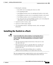
... adapter • Cisco Information Packet, containing warranty, safety, and support information Installing the Switch in a Rack Warning To prevent bodily injury when mounting or servicing this unit in a partially filled rack, load the rack from the bottom to the top with stabilizing devices, install the stabilizers before mounting or servicing the unit in the rack. The rack-mounting brackets supplied...
... adapter • Cisco Information Packet, containing warranty, safety, and support information Installing the Switch in a Rack Warning To prevent bodily injury when mounting or servicing this unit in a partially filled rack, load the rack from the bottom to the top with stabilizing devices, install the stabilizers before mounting or servicing the unit in the rack. The rack-mounting brackets supplied...
Installation Guide
Page 68
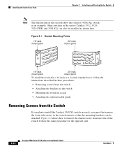
... attached. Follow the same procedure for the opposite side. 2-10 Catalyst 3500 Series XL Hardware Installation Guide 78-6456-04 Figure 2-1 Bracket Mounting Points 19" rack mount point 24" rack mount point 38398 19" rack mount point 24" rack mount point To install the switch in a 19-inch or a 24-inch standard rack, follow the instructions described in these procedures: • Removing...
... attached. Follow the same procedure for the opposite side. 2-10 Catalyst 3500 Series XL Hardware Installation Guide 78-6456-04 Figure 2-1 Bracket Mounting Points 19" rack mount point 24" rack mount point 38398 19" rack mount point 24" rack mount point To install the switch in a 19-inch or a 24-inch standard rack, follow the instructions described in these procedures: • Removing...
Installation Guide
Page 71
... the power cord to the left or right bracket. 78-6456-04 Catalyst 3500 Series XL Hardware Installation Guide 2-13 Chapter 2 Installing and Starting Up the Switch Installing the Switch in a Rack Mounting the Switch in a Rack After the brackets are using the Cisco RPS, see the Cisco RPS documentation for 2 seconds, and then it flashes green while the...
... the power cord to the left or right bracket. 78-6456-04 Catalyst 3500 Series XL Hardware Installation Guide 2-13 Chapter 2 Installing and Starting Up the Switch Installing the Switch in a Rack Mounting the Switch in a Rack After the brackets are using the Cisco RPS, see the Cisco RPS documentation for 2 seconds, and then it flashes green while the...
Installation Guide
Page 72
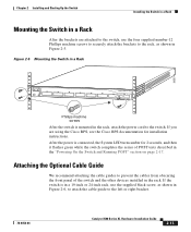
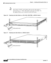
... guide screw 28324 2-14 Catalyst 3500 Series XL Hardware Installation Guide 78-6456-04 22441 Installing the Switch in a Rack Chapter 2 Installing and Starting Up the Switch Note The Catalyst 3548 XL switch ships with a special cable... guide as shown in Figure 2-7. Figure 2-6 Attaching the Cable Guide to a 3512, 3524, 3524-PWR, or 3508 XL Switch 1 MODE SYSTEM RPS 2 3 4 5 STATUS UTIL DUPLX SPEED 6 7 8 Cable guide screw Figure 2-7 Attaching the Cable Guide to 48 cables. Use the supplied black screw to mount...
... guide screw 28324 2-14 Catalyst 3500 Series XL Hardware Installation Guide 78-6456-04 22441 Installing the Switch in a Rack Chapter 2 Installing and Starting Up the Switch Note The Catalyst 3548 XL switch ships with a special cable... guide as shown in Figure 2-7. Figure 2-6 Attaching the Cable Guide to a 3512, 3524, 3524-PWR, or 3508 XL Switch 1 MODE SYSTEM RPS 2 3 4 5 STATUS UTIL DUPLX SPEED 6 7 8 Cable guide screw Figure 2-7 Attaching the Cable Guide to 48 cables. Use the supplied black screw to mount...
Installation Guide
Page 145
Appendix C Translated Safety Warnings • • • • • • Chassis Warning-Rack-Mounting and Servicing 78-6456-04 Catalyst 3500 Series XL Hardware Installation Guide C-37
Appendix C Translated Safety Warnings • • • • • • Chassis Warning-Rack-Mounting and Servicing 78-6456-04 Catalyst 3500 Series XL Hardware Installation Guide C-37
Installation Guide
Page 153
...GBIC ports B-3 pinouts B-4 See also connectors and cables cautions xiii CGMP 1-3 Catalyst 3500 Series XL Hardware Installation Guide IN-1 and 24-inch racks 2-9 A AC power connecting to 2-17 connector 1-22 specifications A-1, A-2, ...A-3 adapter pinouts, terminal RJ-45-to-DB-25 B-7 RJ-45-to-DB-9 B-6 78-6456-04 INDEX addresses, assigning IP 2-26 agency approvals A-3 altitude A-1, A-2, A-3 applications (network examples) 1-25 autonegotiation 1-8 B bandwidth utilization 1-19, 1-20 BOOTP 2-29 brackets See mounting...
...GBIC ports B-3 pinouts B-4 See also connectors and cables cautions xiii CGMP 1-3 Catalyst 3500 Series XL Hardware Installation Guide IN-1 and 24-inch racks 2-9 A AC power connecting to 2-17 connector 1-22 specifications A-1, A-2, ...A-3 adapter pinouts, terminal RJ-45-to-DB-25 B-7 RJ-45-to-DB-9 B-6 78-6456-04 INDEX addresses, assigning IP 2-26 agency approvals A-3 altitude A-1, A-2, A-3 applications (network examples) 1-25 autonegotiation 1-8 B bandwidth utilization 1-19, 1-20 BOOTP 2-29 brackets See mounting...
Installation Guide
Page 154
...warning rack-mounting, servicing C-33 circuit breaker (15A) warning C-21 Cisco Access Analog Trunk Gateway 1-33 Cisco Access Digital Trunk Gateway 1-33 Cisco CallManager software 1-31, 1-33 Cisco Cluster Management Suite 1-24 Cisco Group Management Protocol (CGMP) 1-3 Cisco IP Phones 1-8, 1-31 connecting 2-19 Cisco RPS 1-22 connecting to 2-17 LED 1-15 Cisco ... D default characteristics of the console port 2-23 default configuration 2-30 to 2-31 designing your network, examples 1-25 desk mounting 2-17 diagnosing problems 3-3 IN-2 Catalyst 3500 Series XL Hardware Installation Guide 78-6456-04
...warning rack-mounting, servicing C-33 circuit breaker (15A) warning C-21 Cisco Access Analog Trunk Gateway 1-33 Cisco Access Digital Trunk Gateway 1-33 Cisco CallManager software 1-31, 1-33 Cisco Cluster Management Suite 1-24 Cisco Group Management Protocol (CGMP) 1-3 Cisco IP Phones 1-8, 1-31 connecting 2-19 Cisco RPS 1-22 connecting to 2-17 LED 1-15 Cisco ... D default characteristics of the console port 2-23 default configuration 2-30 to 2-31 designing your network, examples 1-25 desk mounting 2-17 diagnosing problems 3-3 IN-2 Catalyst 3500 Series XL Hardware Installation Guide 78-6456-04
Installation Guide
Page 155
...xviii document conventions xii duplex LED 1-17, 1-18 E electrical noise, avoiding 2-8 electromagnetic interference (EMI) A-3 EMC regulatory statements 2-5 Enterprise Edition software, switches running 1-2 examples, network configuration 1-25 F features 1-1 to 1-3 flooding, traffic control 2-30 front panel 1-5 to 1-20 10/100 ports 1-7 1000BaseX... A-2, A-3 I IEEE 802.1p 1-3 inline power 1-8, 2-18 to 2-19 LED 1-17, 1-19 troubleshooting 3-6 installation guidelines 2-7 rack-mount 2-9 See also procedures warning C-9 Inter-Switch Link (ISL) 1-3 Catalyst 3500 Series XL Hardware Installation Guide IN-3
...xviii document conventions xii duplex LED 1-17, 1-18 E electrical noise, avoiding 2-8 electromagnetic interference (EMI) A-3 EMC regulatory statements 2-5 Enterprise Edition software, switches running 1-2 examples, network configuration 1-25 F features 1-1 to 1-3 flooding, traffic control 2-30 front panel 1-5 to 1-20 10/100 ports 1-7 1000BaseX... A-2, A-3 I IEEE 802.1p 1-3 inline power 1-8, 2-18 to 2-19 LED 1-17, 1-19 troubleshooting 3-6 installation guidelines 2-7 rack-mount 2-9 See also procedures warning C-9 Inter-Switch Link (ISL) 1-3 Catalyst 3500 Series XL Hardware Installation Guide IN-3
Installation Guide
Page 156
...procedures 2-24 IP setup 2-26 J jewelry removal warning C-10 L LAN-to-phone jack 2-19 LEDs Catalyst 3508G XL front panel 1-11 Catalyst 3512 and 3524 XL front panel 1-12 Catalyst 3548 XL front panel 1-14 color meanings 1-18 duplex 1-17, 1-18 half-duplex 1-17, 1-18... power M management features and defaults 2-30 Mode button 1-11, 1-16 Mode label (on Catalyst 3548 XL only) 1-16 models, switch 1-2 mounting, table or desk 2-17 mounting brackets 2-9 attaching 2-11, 2-15 rack-mount 2-13 wall-mount 2-16 N network configuration examples 1-25 network redundancy values 2-30 noise, electrical 2-8 no on...
...procedures 2-24 IP setup 2-26 J jewelry removal warning C-10 L LAN-to-phone jack 2-19 LEDs Catalyst 3508G XL front panel 1-11 Catalyst 3512 and 3524 XL front panel 1-12 Catalyst 3548 XL front panel 1-14 color meanings 1-18 duplex 1-17, 1-18 half-duplex 1-17, 1-18... power M management features and defaults 2-30 Mode button 1-11, 1-16 Mode label (on Catalyst 3548 XL only) 1-16 models, switch 1-2 mounting, table or desk 2-17 mounting brackets 2-9 attaching 2-11, 2-15 rack-mount 2-13 wall-mount 2-16 N network configuration examples 1-25 network redundancy values 2-30 noise, electrical 2-8 no on...
Installation Guide
Page 157
Index PC, connecting to switch 2-23 performance network design 1-25 performance problems, solving 3-3 performance tuning features 2-30 personnel warning C-7 pinouts 10/100 ports B-2 adapters B-5 to B-7 cable, ...installation 2-7 to 2-17 IP address 2-24 product disposal warning C-31 PSTN 1-33 publications, related xviii Public Switched Telephone Network See PSTN Q qualified personnel warning C-7 R rack installation 2-9 bracket mounting points 2-10 rack-mounting 2-13 rear panel 1-21 to 1-22 clearance 2-8 Redundant Power Supply 78-6456-04 Catalyst 3500 Series XL Hardware Installation Guide IN-5
Index PC, connecting to switch 2-23 performance network design 1-25 performance problems, solving 3-3 performance tuning features 2-30 personnel warning C-7 pinouts 10/100 ports B-2 adapters B-5 to B-7 cable, ...installation 2-7 to 2-17 IP address 2-24 product disposal warning C-31 PSTN 1-33 publications, related xviii Public Switched Telephone Network See PSTN Q qualified personnel warning C-7 R rack installation 2-9 bracket mounting points 2-10 rack-mounting 2-13 rear panel 1-21 to 1-22 clearance 2-8 Redundant Power Supply 78-6456-04 Catalyst 3500 Series XL Hardware Installation Guide IN-5