
Hardware Installation Guide
Page 5
...to Go Next 3-18 Troubleshooting 4-1 Diagnosing Problems 4-1 Verify Switch POST Results 4-2 Monitor Switch LEDs 4-2 Verify Switch Connections 4-2 Bad or Damaged Cable 4-2 Ethernet and Fiber Cables 4-3 Link Status 4-3 Transceiver Module Port ... 3-14 Rack-Mounting 3-15 Attaching Brackets to 1000BASE-T Devices B-2 SFP Module Ports B-3 Dual-Purpose Ports B-3 Catalyst 2960 Switch Hardware Installation Guide v and 100BASE-TX-Compatible Devices B-1 Connecting to the Switch 3-15 Mounting the Switch in a 19-Inch Rack 3-16 Wall-Mounting (with Mounting Screws) 3-7 Under the Desk- Contents 4 C...
...to Go Next 3-18 Troubleshooting 4-1 Diagnosing Problems 4-1 Verify Switch POST Results 4-2 Monitor Switch LEDs 4-2 Verify Switch Connections 4-2 Bad or Damaged Cable 4-2 Ethernet and Fiber Cables 4-3 Link Status 4-3 Transceiver Module Port ... 3-14 Rack-Mounting 3-15 Attaching Brackets to 1000BASE-T Devices B-2 SFP Module Ports B-3 Dual-Purpose Ports B-3 Catalyst 2960 Switch Hardware Installation Guide v and 100BASE-TX-Compatible Devices B-1 Connecting to the Switch 3-15 Mounting the Switch in a 19-Inch Rack 3-16 Wall-Mounting (with Mounting Screws) 3-7 Under the Desk- Contents 4 C...
Hardware Installation Guide
Page 7
... to materials not contained in these conventions and symbols for installing the Catalyst 2960 switch, hereafter known as the switch. It describes the physical and performance characteristics of Ethernet and local area networking. Conventions This document uses these areas, learning ...opportunities including training courses, self-study options, seminars, and career certifications programs are available on the Cisco.com Product Documentation home page. OL-7075-09 Catalyst 2960 Switch...
... to materials not contained in these conventions and symbols for installing the Catalyst 2960 switch, hereafter known as the switch. It describes the physical and performance characteristics of Ethernet and local area networking. Conventions This document uses these areas, learning ...opportunities including training courses, self-study options, seminars, and career certifications programs are available on the Cisco.com Product Documentation home page. OL-7075-09 Catalyst 2960 Switch...
Hardware Installation Guide
Page 9
...Cisco.com site: http://www.cisco.com/en/US/products/hw/modules/ps5455/products_device_support_tables_list.html • Cisco Gigabit Ethernet Transceiver Modules Compatibility Matrix • Cisco 100-Megabit Ethernet SFP Modules Compatibility Matrix • Cisco CWDM SFP Transceiver Compatibility Matrix • Cisco... Cisco Redundant Power System 2300 Hardware Installation Guide • Cisco RPS 675 Redundant Power System Hardware Installation Guide These compatibility matrix documents are a free service and Cisco currently supports RSS Version 2.0. OL-7075-09 Catalyst 2960 Switch Hardware...
...Cisco.com site: http://www.cisco.com/en/US/products/hw/modules/ps5455/products_device_support_tables_list.html • Cisco Gigabit Ethernet Transceiver Modules Compatibility Matrix • Cisco 100-Megabit Ethernet SFP Modules Compatibility Matrix • Cisco CWDM SFP Transceiver Compatibility Matrix • Cisco... Cisco Redundant Power System 2300 Hardware Installation Guide • Cisco RPS 675 Redundant Power System Hardware Installation Guide These compatibility matrix documents are a free service and Cisco currently supports RSS Version 2.0. OL-7075-09 Catalyst 2960 Switch Hardware...

Hardware Installation Guide
Page 11
... traditional wiring closet environment, such as workstations, Cisco Wireless Access Points, Cisco IP Phones, and other network devices including servers, routers, and other network devices. Product Overview 1 C H A P T E R The Catalyst 2960 switch-also referred to as the switch-is an Ethernet switch to which you can deploy these switches outside of the Catalyst 2960 switch. These topics are included: • Features...
... traditional wiring closet environment, such as workstations, Cisco Wireless Access Points, Cisco IP Phones, and other network devices including servers, routers, and other network devices. Product Overview 1 C H A P T E R The Catalyst 2960 switch-also referred to as the switch-is an Ethernet switch to which you can deploy these switches outside of the Catalyst 2960 switch. These topics are included: • Features...

Hardware Installation Guide
Page 12
... 10/100BASE-TX Ethernet ports and 2 10/100/1000BASE-T copper uplink ports (no SFP module slot) The Catalyst 2960-8TC-S, 2960-8TC-L, 2960G-8TC-L, and 2960PD-8TT-L switches are smaller than the other Catalyst 2960 switches. See Chapter 3, "Switch Installation (8-Port Switches)," for the installation instructions for more information. They can be mounted with Cisco prestandard PoE and...
... 10/100BASE-TX Ethernet ports and 2 10/100/1000BASE-T copper uplink ports (no SFP module slot) The Catalyst 2960-8TC-S, 2960-8TC-L, 2960G-8TC-L, and 2960PD-8TT-L switches are smaller than the other Catalyst 2960 switches. See Chapter 3, "Switch Installation (8-Port Switches)," for the installation instructions for more information. They can be mounted with Cisco prestandard PoE and...

Hardware Installation Guide
Page 13
The Catalyst 2960-8TC-L, 2960G-8TC-L, and 2960-8TC-S switches do not have a redundant power system (RPS) connector for an optional Cisco RPS 2300 or Cisco RPS 675 redundant power system that operates on specific switches, see the Cisco Gigabit Ethernet Transceiver Modules Compatibility Matrix at this Cisco.com URL: http://www.cisco.com/en/US/docs/interfaces_modules/transceiver_modules/compatibility...
The Catalyst 2960-8TC-L, 2960G-8TC-L, and 2960-8TC-S switches do not have a redundant power system (RPS) connector for an optional Cisco RPS 2300 or Cisco RPS 675 redundant power system that operates on specific switches, see the Cisco Gigabit Ethernet Transceiver Modules Compatibility Matrix at this Cisco.com URL: http://www.cisco.com/en/US/docs/interfaces_modules/transceiver_modules/compatibility...

Hardware Installation Guide
Page 16
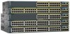
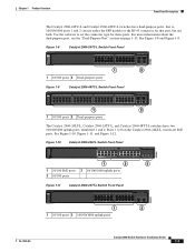
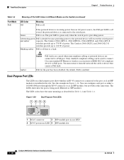
... 20 21 22 23 24 11X 13X 23X Catalyst 2960 Series PoE-24 2X POWER OVER ETHERNET 12X 14X 1 2 24X 204641 1 2 1 10/100 PoE ports 2 Dual-purpose ports Figure 1-6 Catalyst 2960-24PC-S Switch Front Panel 206731 1 2 1 10/100 PoE ports 2 Dual-purpose ports Figure 1-7 Catalyst 2960-24LC-S Switch Front Panel 206730 1 2 3 1 10/100 PoE ports 3 Dual...
... 20 21 22 23 24 11X 13X 23X Catalyst 2960 Series PoE-24 2X POWER OVER ETHERNET 12X 14X 1 2 24X 204641 1 2 1 10/100 PoE ports 2 Dual-purpose ports Figure 1-6 Catalyst 2960-24PC-S Switch Front Panel 206731 1 2 1 10/100 PoE ports 2 Dual-purpose ports Figure 1-7 Catalyst 2960-24LC-S Switch Front Panel 206730 1 2 3 1 10/100 PoE ports 3 Dual...
Hardware Installation Guide
Page 17
...15 16 17 18 19 20 21 22 23 24 Catalyst 2960 Series PoE-8 11X 13X 23X 2X POWER OVER ETHERNET 12X 14X 1 2 24X 1 2 3 1 10/100 PoE ports 3 10/100/1000 uplink ports 2 10/100 ports Figure 1-11 Catalyst 2960-24TT-L Switch Front Panel 204607 SYST RPS STAT DUPLX SPEED MODE ...1 2 1 10/100 ports 2 10/100/1000 uplink ports OL-7075-09 Catalyst 2960 Switch Hardware Installation Guide...
...15 16 17 18 19 20 21 22 23 24 Catalyst 2960 Series PoE-8 11X 13X 23X 2X POWER OVER ETHERNET 12X 14X 1 2 24X 1 2 3 1 10/100 PoE ports 3 10/100/1000 uplink ports 2 10/100 ports Figure 1-11 Catalyst 2960-24TT-L Switch Front Panel 204607 SYST RPS STAT DUPLX SPEED MODE ...1 2 1 10/100 ports 2 10/100/1000 uplink ports OL-7075-09 Catalyst 2960 Switch Hardware Installation Guide...

Hardware Installation Guide
Page 18
...the second member (port 2), port 3 is above port 4, and so on page 1-13. See Figure 1-15 and Figure 1-16. The Catalyst 2960G-24TC-L and Catalyst 2960G-48TC-L switches have two SFP module slots (numbered 1 and 2) and two 10/100/1000 uplink ports (numbered 3 and 4). The SFP module slots ... the SFP module or the RJ-45 connector for these ports. Catalyst 2960 Switch Hardware Installation Guide 1-8 OL-7075-09 Figure 1-13 Catalyst 2960-48PST-L Switch Front Panel 3 1 2 3 4 5 6 SYST 1X RPS STAT DUPLX SPEED PoE MODE 2X POWER OVER ETHERNET 7 8 9 10 11 12 13 14 15 16 17 18...
...the second member (port 2), port 3 is above port 4, and so on page 1-13. See Figure 1-15 and Figure 1-16. The Catalyst 2960G-24TC-L and Catalyst 2960G-48TC-L switches have two SFP module slots (numbered 1 and 2) and two 10/100/1000 uplink ports (numbered 3 and 4). The SFP module slots ... the SFP module or the RJ-45 connector for these ports. Catalyst 2960 Switch Hardware Installation Guide 1-8 OL-7075-09 Figure 1-13 Catalyst 2960-48PST-L Switch Front Panel 3 1 2 3 4 5 6 SYST 1X RPS STAT DUPLX SPEED PoE MODE 2X POWER OVER ETHERNET 7 8 9 10 11 12 13 14 15 16 17 18...

Hardware Installation Guide
Page 21
... that both devices support and full-duplex transmission if the attached device supports it ) and configures itself accordingly. OL-7075-09 Catalyst 2960 Switch Hardware Installation Guide 1-11 In all cases, the attached device must be sure to use Category 3 or Category 4 cables.... interface configuration command in full-duplex or half-duplex mode. Pinouts for copper Ethernet connections and configures the interfaces accordingly. When you connect the switch to workstations, servers, routers, and Cisco IP Phones, be sure that both devices support and full-duplex transmission if ...
... that both devices support and full-duplex transmission if the attached device supports it ) and configures itself accordingly. OL-7075-09 Catalyst 2960 Switch Hardware Installation Guide 1-11 In all cases, the attached device must be sure to use Category 3 or Category 4 cables.... interface configuration command in full-duplex or half-duplex mode. Pinouts for copper Ethernet connections and configures the interfaces accordingly. When you connect the switch to workstations, servers, routers, and Cisco IP Phones, be sure that both devices support and full-duplex transmission if ...

Hardware Installation Guide
Page 22
The Catalyst 2960-24LT-L and 2960-24LC-S switches deliver a maximum power output of security. In that present a shock hazard may exist on Power over Ethernet (PoE) circuits if interconnections are made using such interconnection methods, unless the exposed metal parts are located within a restricted access ... key or other means of approximately 124-W PoE power. • On a per-port basis, you can connect a Cisco IP Phone or Cisco Aironet Access Point to a Catalyst 2960 PoE switch 10/100 port and to it. Never: When you select the Auto setting, the port provides power only if a ...
The Catalyst 2960-24LT-L and 2960-24LC-S switches deliver a maximum power output of security. In that present a shock hazard may exist on Power over Ethernet (PoE) circuits if interconnections are made using such interconnection methods, unless the exposed metal parts are located within a restricted access ... key or other means of approximately 124-W PoE power. • On a per-port basis, you can connect a Cisco IP Phone or Cisco Aironet Access Point to a Catalyst 2960 PoE switch 10/100 port and to it. Never: When you select the Auto setting, the port provides power only if a ...

Hardware Installation Guide
Page 23
... port LED is considered as an SFP module port. Through a 10/100/1000 port from your Cisco representative. (See Figure 1-22.) OL-7075-09 Catalyst 2960 Switch Hardware Installation Guide 1-13 You can order it from an upstream Ethernet switch that provides power (complies with LC connectors to connect to a fiber-optic SFP module. The...
... port LED is considered as an SFP module port. Through a 10/100/1000 port from your Cisco representative. (See Figure 1-22.) OL-7075-09 Catalyst 2960 Switch Hardware Installation Guide 1-13 You can order it from an upstream Ethernet switch that provides power (complies with LC connectors to connect to a fiber-optic SFP module. The...
Hardware Installation Guide
Page 28
...LEDs on . The LEDs show whether an RJ-45 connector is connected to the port, or if an SFP module is being used to connect Cisco prestandard IP Phones or wireless access points or IEEE 802.3af-compliant devices to a PoE port. Alternating green PoE is providing power. Amber Caution PoE...Meaning PoE is on a dual-purpose port show how the port is installed in the slot. The Catalyst 2960-24LT-L and 2960-24LC-S switches provide up to 370 W of power. You can be used (Ethernet or SFP module). PoE for the port has been disabled. If the powered device is receiving power from...
...LEDs on . The LEDs show whether an RJ-45 connector is connected to the port, or if an SFP module is being used to connect Cisco prestandard IP Phones or wireless access points or IEEE 802.3af-compliant devices to a PoE port. Alternating green PoE is providing power. Amber Caution PoE...Meaning PoE is on a dual-purpose port show how the port is installed in the slot. The Catalyst 2960-24LT-L and 2960-24LC-S switches provide up to 370 W of power. You can be used (Ethernet or SFP module). PoE for the port has been disabled. If the powered device is receiving power from...
Hardware Installation Guide
Page 32
...the CLI either by connecting your management station directly to the switch console port or by using Telnet from anywhere in your network through Gigabit Ethernet connections. 1-22 Catalyst 2960 Switch Hardware Installation Guide OL-7075-09 You can access the device ... and to view switch status and performance information. See the Catalyst 2960 Switch Command Reference on the switch. You can use Cisco Configuration Engine to automate initial configurations and configuration updates on Cisco.com for an explanation of Cisco LAN switches, core switches, routers, access points...
...the CLI either by connecting your management station directly to the switch console port or by using Telnet from anywhere in your network through Gigabit Ethernet connections. 1-22 Catalyst 2960 Switch Hardware Installation Guide OL-7075-09 You can access the device ... and to view switch status and performance information. See the Catalyst 2960 Switch Command Reference on the switch. You can use Cisco Configuration Engine to automate initial configurations and configuration updates on Cisco.com for an explanation of Cisco LAN switches, core switches, routers, access points...
Hardware Installation Guide
Page 34
... to use the correct hardware or to the switch, install an RPS connector cover on equipment that exceeds the maximum recommended ambient temperature of the switch. Preparing for the Catalyst 2960 Switch guide. Statement 48 Warning Ethernet cables must be shielded when used in an area...Installation Chapter 2 Switch Installation (24- Statement 171 Warning If a redundant power system (RPS) is connected to the power source. Statement 17B Warning Before working on the back of 113•F (45•C). Statement 265 Warning Attach only the following Cisco RPS model to ...
... to use the correct hardware or to the switch, install an RPS connector cover on equipment that exceeds the maximum recommended ambient temperature of the switch. Preparing for the Catalyst 2960 Switch guide. Statement 48 Warning Ethernet cables must be shielded when used in an area...Installation Chapter 2 Switch Installation (24- Statement 171 Warning If a redundant power system (RPS) is connected to the power source. Statement 17B Warning Before working on the back of 113•F (45•C). Statement 265 Warning Attach only the following Cisco RPS model to ...
Hardware Installation Guide
Page 35
... where the equipment is available. Statement 1044 OL-7075-09 Catalyst 2960 Switch Hardware Installation Guide 2-3 Statement 1008 Warning This unit is provided with integral circuit protection: 10/100/1000 Ethernet. Statement 1019 Warning This equipment must be mounted at the bottom...network termination unit with stabilizing devices, install the stabilizers before mounting or servicing the unit in restricted access areas. Chapter 2 Switch Installation (24- Statement 1006 Warning Class 1 laser product. The following ports must be handled according to install, replace,...
... where the equipment is available. Statement 1044 OL-7075-09 Catalyst 2960 Switch Hardware Installation Guide 2-3 Statement 1008 Warning This unit is provided with integral circuit protection: 10/100/1000 Ethernet. Statement 1019 Warning This equipment must be mounted at the bottom...network termination unit with stabilizing devices, install the stabilizers before mounting or servicing the unit in restricted access areas. Chapter 2 Switch Installation (24- Statement 1006 Warning Class 1 laser product. The following ports must be handled according to install, replace,...

Hardware Installation Guide
Page 36
...disconnected last. You must comply with cooling mechanisms, such as metal flakes from the switch to all Catalyst 2960 switches except for Installation Chapter 2 Switch Installation (24- Statement 1072 Warning No user-serviceable parts inside the chassis, which lists...working environments and acceptable levels of the hazard. These standards provide guidelines for Particulate Matter Cisco Ethernet switches are equipped with local and national electrical codes. Catalyst 2960 Switch Hardware Installation Guide 2-4 OL-7075-09 Do not open. However, these requirements: &#...
...disconnected last. You must comply with cooling mechanisms, such as metal flakes from the switch to all Catalyst 2960 switches except for Installation Chapter 2 Switch Installation (24- Statement 1072 Warning No user-serviceable parts inside the chassis, which lists...working environments and acceptable levels of the hazard. These standards provide guidelines for Particulate Matter Cisco Ethernet switches are equipped with local and national electrical codes. Catalyst 2960 Switch Hardware Installation Guide 2-4 OL-7075-09 Do not open. However, these requirements: &#...
Hardware Installation Guide
Page 46
..., and run Express Setup. Connecting to all switches except the Catalyst 2960-8TC-L, 2960-8TC-S, 2960G-8TC-L, and 2960PD-8TT-L switches. See the "Verifying Switch Operation" section on page 2-20 to Appendix C, "Configuring the Switch with the CLI-Based Setup Program." Place the switch on them for configuring the Ethernet ports: • Let the ports autonegotiate both...
..., and run Express Setup. Connecting to all switches except the Catalyst 2960-8TC-L, 2960-8TC-S, 2960G-8TC-L, and 2960PD-8TT-L switches. See the "Verifying Switch Operation" section on page 2-20 to Appendix C, "Configuring the Switch with the CLI-Based Setup Program." Place the switch on them for configuring the Ethernet ports: • Let the ports autonegotiate both...

Hardware Installation Guide
Page 47
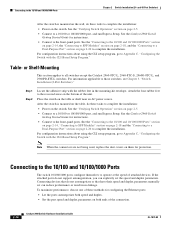
...provide the uplink optical interfaces, laser send (TX) and laser receive (RX). Step 1 When connecting to workstations, servers, routers, and Cisco IP Phones, connect a straight-through 3 to 30 seconds, and then the port LED turns green. See Chapter 4, "Troubleshooting," for this feature, see... link. Figure 2-13 Connecting to an Ethernet Port 11XX SYST RPS STAT DUPLX 111X SPEED 2X MODE 12X 204623 Step 2 Step 3 Step 4 Connect the other end of the cable to the Catalyst 2960 switch release notes for reliable communications. Chapter 2 Switch Installation (24- You can take up...
...provide the uplink optical interfaces, laser send (TX) and laser receive (RX). Step 1 When connecting to workstations, servers, routers, and Cisco IP Phones, connect a straight-through 3 to 30 seconds, and then the port LED turns green. See Chapter 4, "Troubleshooting," for this feature, see... link. Figure 2-13 Connecting to an Ethernet Port 11XX SYST RPS STAT DUPLX 111X SPEED 2X MODE 12X 204623 Step 2 Step 3 Step 4 Connect the other end of the cable to the Catalyst 2960 switch release notes for reliable communications. Chapter 2 Switch Installation (24- You can take up...

Hardware Installation Guide
Page 56
...power and ground and can cause severe bodily injury and equipment damage. Statement 1019 Catalyst 2960 Switch Hardware Installation Guide 3-2 OL-7075-09 Metal objects will heat up when connected to a power-over-ethernet (PoE) IEEE 802.3af compliant power source or an IEC60950 compliant limited power ... devices, install the stabilizers before connecting the system to the terminals. Statement 171 Warning Warning statement 353 applies only to the Catalyst 2960PD-8TT-L switch: Warning This product must be mounted at the bottom of the rack. • If the rack is provided with the ...
...power and ground and can cause severe bodily injury and equipment damage. Statement 1019 Catalyst 2960 Switch Hardware Installation Guide 3-2 OL-7075-09 Metal objects will heat up when connected to a power-over-ethernet (PoE) IEEE 802.3af compliant power source or an IEC60950 compliant limited power ... devices, install the stabilizers before connecting the system to the terminals. Statement 171 Warning Warning statement 353 applies only to the Catalyst 2960PD-8TT-L switch: Warning This product must be mounted at the bottom of the rack. • If the rack is provided with the ...


