
Hardware Installation Guide
Page 2
... with the limits for FCC compliance of Class A devices: This equipment has been tested and found to operate the product. The use the equipment may cause harmful interference to the Human Network are registered trademarks of actual IP addresses in part 15 of California. Catalyst 2960 Switch Hardware Installation Guide © 2005-2010 Cisco Systems, Inc. Copyright © 1981, Regents of the...
... with the limits for FCC compliance of Class A devices: This equipment has been tested and found to operate the product. The use the equipment may cause harmful interference to the Human Network are registered trademarks of actual IP addresses in part 15 of California. Catalyst 2960 Switch Hardware Installation Guide © 2005-2010 Cisco Systems, Inc. Copyright © 1981, Regents of the...

Hardware Installation Guide
Page 21
... 4 cables. You can use the mdix auto interface configuration command in the CLI to enable the automatic medium-dependent interface crossover (auto-MDIX) feature. You can also set these ports for autonegotiation, it ) and configures itself accordingly. You can use either a crossover or a straight-through or crossover cable for connections to enable the auto-MDIX feature. OL-7075-09 Catalyst 2960 Switch Hardware Installation Guide 1-11 When you connect the switch to workstations, servers, routers, and Cisco IP Phones...
... 4 cables. You can use the mdix auto interface configuration command in the CLI to enable the automatic medium-dependent interface crossover (auto-MDIX) feature. You can also set these ports for autonegotiation, it ) and configures itself accordingly. You can use either a crossover or a straight-through or crossover cable for connections to enable the auto-MDIX feature. OL-7075-09 Catalyst 2960 Switch Hardware Installation Guide 1-11 When you connect the switch to workstations, servers, routers, and Cisco IP Phones...

Hardware Installation Guide
Page 22
... default. - In that case, the PoE port becomes the backup power source for each 10/100 PoE port: - The Cisco prestandard PoE is also supported for Cisco IP Phones and Cisco Aironet Access Points. • Each of the PoE ports on the Catalyst 2960 switches deliver up to an AC power source for redundant power. For information about configuring and monitoring PoE ports, see the documentation that came with the switch. The device manager, Network Assistant, and the CLI provide PoE settings...
... default. - In that case, the PoE port becomes the backup power source for each 10/100 PoE port: - The Cisco prestandard PoE is also supported for Cisco IP Phones and Cisco Aironet Access Points. • Each of the PoE ports on the Catalyst 2960 switches deliver up to an AC power source for redundant power. For information about configuring and monitoring PoE ports, see the documentation that came with the switch. The device manager, Network Assistant, and the CLI provide PoE settings...

Hardware Installation Guide
Page 23
... fiber-optic connections. The port LED is on the active connector. You use Gigabit Ethernet SFP modules for Gigabit uplink connections and 100-Megabit SFP modules for 100-Megabit connections to a copper SFP module. For information about configuring speed and duplex settings for your SFP module documentation or the release notes for a dual-purpose uplink, see Appendix B, "Connector and Cable Specifications." Chapter 1 Product Overview Front Panel Description SFP Module Slots The Catalyst 2960 switches (other switches. Power Input Port (Catalyst 2960PD-8TT-L Switch) The Catalyst...
... fiber-optic connections. The port LED is on the active connector. You use Gigabit Ethernet SFP modules for Gigabit uplink connections and 100-Megabit SFP modules for 100-Megabit connections to a copper SFP module. For information about configuring speed and duplex settings for your SFP module documentation or the release notes for a dual-purpose uplink, see Appendix B, "Connector and Cable Specifications." Chapter 1 Product Overview Front Panel Description SFP Module Slots The Catalyst 2960 switches (other switches. Power Input Port (Catalyst 2960PD-8TT-L Switch) The Catalyst...
Hardware Installation Guide
Page 32
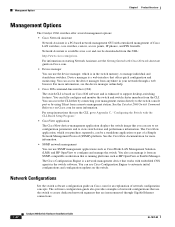
... Command Reference on Cisco.com for more information. • SNMP network management You can access the device manager from an SNMP-compatible workstation that is a web interface that offers quick configuration and monitoring. The Cisco Configuration Engine is in the switch memory, to automate initial configurations and configuration updates on Cisco.com for an explanation of Cisco LAN switches, core switches, routers, access points, IP phones, and PIX firewalls. You can fully configure and monitor the switch and switch cluster members from a remote management station. Network...
... Command Reference on Cisco.com for more information. • SNMP network management You can access the device manager from an SNMP-compatible workstation that is a web interface that offers quick configuration and monitoring. The Cisco Configuration Engine is in the switch memory, to automate initial configurations and configuration updates on Cisco.com for an explanation of Cisco LAN switches, core switches, routers, access points, IP phones, and PIX firewalls. You can fully configure and monitor the switch and switch cluster members from a remote management station. Network...
Hardware Installation Guide
Page 34
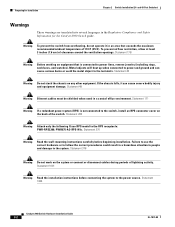
... wall-mounting instructions carefully before connecting the system to the RPS receptacle: PWR-RPS2300, PWR675-AC-RPS-N1=. Statement 43 Warning Do not stack the chassis on equipment that exceeds the maximum recommended ambient temperature of clearance around the ventilation openings. Statement 1004 Catalyst 2960 Switch Hardware Installation Guide 2-2 OL-7075-09 Statement 265 Warning Attach only the following Cisco RPS model...
... wall-mounting instructions carefully before connecting the system to the RPS receptacle: PWR-RPS2300, PWR675-AC-RPS-N1=. Statement 43 Warning Do not stack the chassis on equipment that exceeds the maximum recommended ambient temperature of clearance around the ventilation openings. Statement 1004 Catalyst 2960 Switch Hardware Installation Guide 2-2 OL-7075-09 Statement 265 Warning Attach only the following Cisco RPS model...

Hardware Installation Guide
Page 36
... contaminant buildup inside . Statement 1072 Warning No user-serviceable parts inside the chassis, which lists the cable specifications for 1000BASE-X and 100BASE-X SFP modules for the Catalyst 2960 switch. Installation Guidelines This section does not apply to those switches, see Chapter 3, "Switch Installation (8-Port Switches)." When you determine where to observe these fans and blowers can result in Table B-1 on Power over Ethernet (PoE) circuits if interconnections are made aware of the...
... contaminant buildup inside . Statement 1072 Warning No user-serviceable parts inside the chassis, which lists the cable specifications for 1000BASE-X and 100BASE-X SFP modules for the Catalyst 2960 switch. Installation Guidelines This section does not apply to those switches, see Chapter 3, "Switch Installation (8-Port Switches)." When you determine where to observe these fans and blowers can result in Table B-1 on Power over Ethernet (PoE) circuits if interconnections are made aware of the...

Hardware Installation Guide
Page 38
... time and then reflects the switch operating status. If a switch fails POST, the System LED turns amber. Call Cisco technical support representative if your specific switch; After a successful POST, disconnect the power cord from the bottom to the top with stabilizing devices, install the stabilizers before mounting or servicing the unit in the "Installing the Switch" section on , it is provided with the heaviest component at the bottom of tests...
... time and then reflects the switch operating status. If a switch fails POST, the System LED turns amber. Call Cisco technical support representative if your specific switch; After a successful POST, disconnect the power cord from the bottom to the top with stabilizing devices, install the stabilizers before mounting or servicing the unit in the "Installing the Switch" section on , it is provided with the heaviest component at the bottom of tests...
Hardware Installation Guide
Page 45
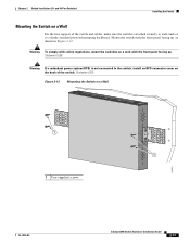
..., mount the switches on a Wall For the best support of the switch. Statement 266 Warning If a redundant power system (RPS) is attached securely to wall studs or to the switch, install an RPS connector cover on a Wall 11X 12X 11X 1X 12X 11X 1X 12X 1X 1X 11X 1X 12X MODE STASCPKEDEUDPSLTXAMTASRTPRSSYST 1 1 1 User-supplied screws 204621 OL-7075-09 Catalyst 2960 Switch Hardware Installation Guide 2-13...
..., mount the switches on a Wall For the best support of the switch. Statement 266 Warning If a redundant power system (RPS) is attached securely to wall studs or to the switch, install an RPS connector cover on a Wall 11X 12X 11X 1X 12X 11X 1X 12X 1X 1X 11X 1X 12X MODE STASCPKEDEUDPSLTXAMTASRTPRSSYST 1 1 1 User-supplied screws 204621 OL-7075-09 Catalyst 2960 Switch Hardware Installation Guide 2-13...

Hardware Installation Guide
Page 47
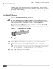
...of SFP modules that the Catalyst 2960 switch supports. You can take up to cabling problems. Reconfigure and reboot the connected device if necessary. For configuration information for cable OL-7075-09 Catalyst 2960 Switch Hardware Installation Guide 2-15 The port LED turns on page B-4 for this feature, see the switch software configuration guide or the switch command reference. See the "SFP Module Cable Specifications" section on when both the switch and the connected device have established link. Chapter 2 Switch Installation (24- Installing and Removing SFP Modules SFP...
...of SFP modules that the Catalyst 2960 switch supports. You can take up to cabling problems. Reconfigure and reboot the connected device if necessary. For configuration information for cable OL-7075-09 Catalyst 2960 Switch Hardware Installation Guide 2-15 The port LED turns on page B-4 for this feature, see the switch software configuration guide or the switch command reference. See the "SFP Module Cable Specifications" section on when both the switch and the connected device have established link. Chapter 2 Switch Installation (24- Installing and Removing SFP Modules SFP...
Hardware Installation Guide
Page 48
... all cables before removing or installing an SFP module. Note On some SFP modules, the send and receive (TX and RX) markings might be replaced by arrows that you feel the connector on the chassis. Removing and installing an SFP module can shorten its useful life. For detailed instructions on the Catalyst 2960 switch. and 48-Port Switches) stipulations for SFP module connections. Cisco SFP modules and the Catalyst 2960 switch support the Quality ID feature. Installing and Removing SFP Modules Chapter 2 Switch Installation...
... all cables before removing or installing an SFP module. Note On some SFP modules, the send and receive (TX and RX) markings might be replaced by arrows that you feel the connector on the chassis. Removing and installing an SFP module can shorten its useful life. For detailed instructions on the Catalyst 2960 switch. and 48-Port Switches) stipulations for SFP module connections. Cisco SFP modules and the Catalyst 2960 switch support the Quality ID feature. Installing and Removing SFP Modules Chapter 2 Switch Installation...

Hardware Installation Guide
Page 57
...: 10/100/1000 Ethernet. Chapter 3 Switch Installation (8-Port Switches) Preparing for Installation Warning This equipment must be made first and disconnected last. Warning For connections outside the building where the equipment is available. and 48-Port Switches)." Statement 1044 Warning When installing or replacing the unit, the ground connection must always be grounded. Statement 1046 Warning No user-serviceable parts inside. Do not open. We strongly...
...: 10/100/1000 Ethernet. Chapter 3 Switch Installation (8-Port Switches) Preparing for Installation Warning This equipment must be made first and disconnected last. Warning For connections outside the building where the equipment is available. and 48-Port Switches)." Statement 1044 Warning When installing or replacing the unit, the ground connection must always be grounded. Statement 1046 Warning No user-serviceable parts inside. Do not open. We strongly...
Hardware Installation Guide
Page 73
... about the switch. They show failures in the power-on the front panel provide troubleshooting information about the switch. Troubleshooting 4 C H A P T E R The LEDs on page 1-14. You can also get statistics from the browser interface, from the command-line interface (CLI), or from an SNMP workstation. See the software configuration guide, the switch command reference guide on page 4-4 OL-7075-09 Catalyst 2960 Switch Hardware Installation Guide 4-1 See the software configuration guide and the switch command reference on Cisco.com or the documentation that came...
... about the switch. They show failures in the power-on the front panel provide troubleshooting information about the switch. Troubleshooting 4 C H A P T E R The LEDs on page 1-14. You can also get statistics from the browser interface, from the command-line interface (CLI), or from an SNMP workstation. See the software configuration guide, the switch command reference guide on page 4-4 OL-7075-09 Catalyst 2960 Switch Hardware Installation Guide 4-1 See the software configuration guide and the switch command reference on Cisco.com or the documentation that came...

Hardware Installation Guide
Page 75
... loose connections. for more information about cabling, see Appendix B, "Connector and Cable Specifications." • For copper connections, determine if a crossover cable was used when a straight-through cable was required or the reverse. Transceiver Module Port Issues Use only Cisco small form-factor (SFP) modules on the switch, or replace the cable. Verify that both sides have link. OL-7075-09 Catalyst 2960 Switch Hardware Installation Guide 4-3 Enable auto-MDIX on the switch. Link Status Verify that this module supports this...
... loose connections. for more information about cabling, see Appendix B, "Connector and Cable Specifications." • For copper connections, determine if a crossover cable was used when a straight-through cable was required or the reverse. Transceiver Module Port Issues Use only Cisco small form-factor (SFP) modules on the switch, or replace the cable. Verify that both sides have link. OL-7075-09 Catalyst 2960 Switch Hardware Installation Guide 4-3 Enable auto-MDIX on the switch. Link Status Verify that this module supports this...
Hardware Installation Guide
Page 76
... default) and an aggressive mode. For information about enabling UDLD on fiber-optic connections. Monitor Switch Performance Review these sections when you troubleshoot switch performance problems: • Speed, Duplex, and Autonegotiation, page 4-4 • Autonegotiation and NIC Cards, page 4-5 • Cabling Distance, page 4-5 Speed, Duplex, and Autonegotiation If the port statistics show interfaces privileged EXEC command to be the problem. This can identify the end device MAC address in the software configuration guide. A broken fiber-optic cable...
... default) and an aggressive mode. For information about enabling UDLD on fiber-optic connections. Monitor Switch Performance Review these sections when you troubleshoot switch performance problems: • Speed, Duplex, and Autonegotiation, page 4-4 • Autonegotiation and NIC Cards, page 4-5 • Cabling Distance, page 4-5 Speed, Duplex, and Autonegotiation If the port statistics show interfaces privileged EXEC command to be the problem. This can identify the end device MAC address in the software configuration guide. A broken fiber-optic cable...
Hardware Installation Guide
Page 77
... devices to also be causing the problem. OL-7075-09 Catalyst 2960 Switch Hardware Installation Guide 4-5 Upgrade the NIC card driver to the latest version available from the manufacturer. The LEDs stop blinking after about 2 seconds. By default, the switch ports and interfaces are set speed or duplex parameter on the switch. Cabling Distance If the port statistics show excessive FCS, late-collision, or alignment errors, verify that is configured on the connected port. • A port is set...
... devices to also be causing the problem. OL-7075-09 Catalyst 2960 Switch Hardware Installation Guide 4-5 Upgrade the NIC card driver to the latest version available from the manufacturer. The LEDs stop blinking after about 2 seconds. By default, the switch ports and interfaces are set speed or duplex parameter on the switch. Cabling Distance If the port statistics show excessive FCS, late-collision, or alignment errors, verify that is configured on the connected port. • A port is set...
Hardware Installation Guide
Page 95
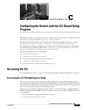
...3, "Switch Installation (8-Port Switches)." Accessing the CLI, page C-1 2. Entering the Initial Configuration Information, page C-4 Accessing the CLI For an unconfigured switch, you connect the switch to the Console Port, page C-3 3. Enter the setup user EXEC command. For installation procedures for mounting your PC or workstation. and 48-Port Switches)," and Chapter 3, "Switch Installation (8-Port Switches)." Starting the Terminal Emulation Software, page C-3 4. To put the switch into Express Setup mode, follow the steps described in the Catalyst 2960 Switch Getting Started Guide...
...3, "Switch Installation (8-Port Switches)." Accessing the CLI, page C-1 2. Entering the Initial Configuration Information, page C-4 Accessing the CLI For an unconfigured switch, you connect the switch to the Console Port, page C-3 3. Enter the setup user EXEC command. For installation procedures for mounting your PC or workstation. and 48-Port Switches)," and Chapter 3, "Switch Installation (8-Port Switches)." Starting the Terminal Emulation Software, page C-3 4. To put the switch into Express Setup mode, follow the steps described in the Catalyst 2960 Switch Getting Started Guide...

Hardware Installation Guide
Page 98
... routers and the Internet. The other LEDs remain solid green. You must assign an IP address and other end of the supplied AC power cord to the power connector on your switch fails POST. Connect the other configuration information necessary for some time and then reflects the switch operating status. POST failures are connecting the switch to a Cisco redundant power system (RPS), refer to display the setup program prompt. If you started...
... routers and the Internet. The other LEDs remain solid green. You must assign an IP address and other end of the supplied AC power cord to the power connector on your switch fails POST. Connect the other configuration information necessary for some time and then reflects the switch operating status. POST failures are connecting the switch to a Cisco redundant power system (RPS), refer to display the setup program prompt. If you started...
Hardware Installation Guide
Page 104
...dual-purpose ports 1-13 LEDs 1-14 to configure switch 2-21, 3-18 diagnosing problems 4-1 disconnecting device warning 2-3 dual-purpose ports connectors and cables B-3 described 1-13 LEDs 1-18 duplex, troubleshooting 4-4 duplex LED 1-16 E electrical noise, avoiding 2-5, 3-4 Ethernet and fiber-optic cable troubleshooting 4-3 Ethernet cable warning 24- Index Cisco IP Phones, connecting to 1-12, 2-15 Cisco RPS See RPS CiscoView 1-22 class 1 laser warning 2-3, 3-2 CLI accessing by using Express Setup C-1 accessing through console port C-2 described 1-22 command-line interface See CLI compliance...
...dual-purpose ports 1-13 LEDs 1-14 to configure switch 2-21, 3-18 diagnosing problems 4-1 disconnecting device warning 2-3 dual-purpose ports connectors and cables B-3 described 1-13 LEDs 1-18 duplex, troubleshooting 4-4 duplex LED 1-16 E electrical noise, avoiding 2-5, 3-4 Ethernet and fiber-optic cable troubleshooting 4-3 Ethernet cable warning 24- Index Cisco IP Phones, connecting to 1-12, 2-15 Cisco RPS See RPS CiscoView 1-22 class 1 laser warning 2-3, 3-2 CLI accessing by using Express Setup C-1 accessing through console port C-2 described 1-22 command-line interface See CLI compliance...

Hardware Installation Guide
Page 107
... twisted-pair 10/100 ports B-6 SunNet Manager 1-22 switch descriptions 1-1 switch powering on 2-5, 3-5 system LED 1-15 T technical specifications A-1 telco racks 2-7, 3-15 Telnet, and accessing the CLI 1-22 temperature, operating A-1 terminal emulation software C-3 trained and qualified personnel warning 2-3 troubleshooting 4-1 to 4-6 OL-7075-09 Index bad or damaged cable 4-2 connection problems 4-2 diagnosing problems 4-1 Ethernet and fiber-optic cables 4-3 link status 4-3 ping end device 4-4 port and interface settings 4-4 POST 4-1 spanning tree loops 4-4 speed, duplex, and autonegotiation...
... twisted-pair 10/100 ports B-6 SunNet Manager 1-22 switch descriptions 1-1 switch powering on 2-5, 3-5 system LED 1-15 T technical specifications A-1 telco racks 2-7, 3-15 Telnet, and accessing the CLI 1-22 temperature, operating A-1 terminal emulation software C-3 trained and qualified personnel warning 2-3 troubleshooting 4-1 to 4-6 OL-7075-09 Index bad or damaged cable 4-2 connection problems 4-2 diagnosing problems 4-1 Ethernet and fiber-optic cables 4-3 link status 4-3 ping end device 4-4 port and interface settings 4-4 POST 4-1 spanning tree loops 4-4 speed, duplex, and autonegotiation...


