Quick Start Guide
Page 1
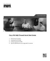
Quick Start Guide Cisco PIX 506E Firewall Quick Start Guide 1 Check Items Included 2 Installing the PIX 506E 3 Configuring the PIX 506E 4 Optional Maintenance and Upgrade Procedures
Quick Start Guide Cisco PIX 506E Firewall Quick Start Guide 1 Check Items Included 2 Installing the PIX 506E 3 Configuring the PIX 506E 4 Optional Maintenance and Upgrade Procedures
Quick Start Guide
Page 2
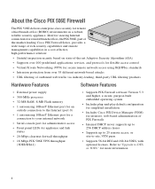
... supports up to 256 DHCP address leases • Supports up to 25 remote access, or site-to DES or 3DES" for remote/branch offices, the PIX 506E, part of CISCO FIRE PIX 506E WALL the market-leading Cisco PIX Firewall Series, provides a wide range of rich security capabilities and remote management capabilities in a robust, reliable security appliance.
... supports up to 256 DHCP address leases • Supports up to 25 remote access, or site-to DES or 3DES" for remote/branch offices, the PIX 506E, part of CISCO FIRE PIX 506E WALL the market-leading Cisco PIX Firewall Series, provides a wide range of rich security capabilities and remote management capabilities in a robust, reliable security appliance.
Quick Start Guide
Page 3
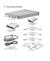
1 Check Items Included ACT LINK ETHERNET 1 ACT LINK ETHERNET 0 USB CONSOLE DC POWER INPUT Cisco PIX 506E Console cable adapter (29-0810-01) Power supply and cable (US shown) 506E power supply (341-0007-01) PC terminal adapter (74-0495-01) Blue console cable (72-1259-01) Yellow Ethernet cable (72-1482-01) ProdFuicCrteisCwcDaollPIX Yellow Ethernet cable (72-1482-01) CGoumSidapefleiatyncaend QGuuiPicdkIeXS5ta0r6tE Documentation 3
1 Check Items Included ACT LINK ETHERNET 1 ACT LINK ETHERNET 0 USB CONSOLE DC POWER INPUT Cisco PIX 506E Console cable adapter (29-0810-01) Power supply and cable (US shown) 506E power supply (341-0007-01) PC terminal adapter (74-0495-01) Blue console cable (72-1259-01) Yellow Ethernet cable (72-1482-01) ProdFuicCrteisCwcDaollPIX Yellow Ethernet cable (72-1482-01) CGoumSidapefleiatyncaend QGuuiPicdkIeXS5ta0r6tE Documentation 3
Quick Start Guide
Page 4
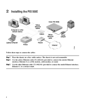
... Ethernet interface, Ethernet 0, to a switch or hub. 4 Use the other network device Laptop computer Printer Yellow Ethernet cables Switch Cisco PIX 506E ACT ETHERNET 1 LINK ACT ETHERNET 0 LINK USB DC CONSOLE IPNOPWUETR Yellow Ethernet cable Power adapter Router Internet 71116 Follow these steps to...Step 1 Step 2 Step 3 Place the chassis on a flat, stable surface. The chassis is not rack mountable. 2 Installing the PIX 506E Computer or other Ethernet cable (72-1482-01) provided to connect the inside Ethernet interface, Ethernet 1, to a DSL modem, cable modem, or ...
... Ethernet interface, Ethernet 0, to a switch or hub. 4 Use the other network device Laptop computer Printer Yellow Ethernet cables Switch Cisco PIX 506E ACT ETHERNET 1 LINK ACT ETHERNET 0 LINK USB DC CONSOLE IPNOPWUETR Yellow Ethernet cable Power adapter Router Internet 71116 Follow these steps to...Step 1 Step 2 Step 3 Place the chassis on a flat, stable surface. The chassis is not rack mountable. 2 Installing the PIX 506E Computer or other Ethernet cable (72-1482-01) provided to connect the inside Ethernet interface, Ethernet 1, to a DSL modem, cable modem, or ...
Quick Start Guide
Page 5
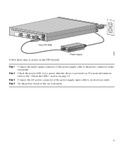
Set the power switch to the on . Check the power LED, if it is green, then the device is powered on (|) position. 5 For more information, refer to the "Check the LEDs" section on the rear panel. 67932 ACT LINK ETHERNET 1 ACT LINK ETHERNET 0 DC POWER USB CONSOLE INPUT DC POWER INPUT Cisco PIX 506E Follow these steps to power on the PIX Firewall: Power supply Step 1 Step 2 Step 3 Step 4 Connect the small, square connector of the power supply input cable to an electrical outlet. Connect the AC power connector of the power supply cable to the power connector on page 11.
Set the power switch to the on . Check the power LED, if it is green, then the device is powered on (|) position. 5 For more information, refer to the "Check the LEDs" section on the rear panel. 67932 ACT LINK ETHERNET 1 ACT LINK ETHERNET 0 DC POWER USB CONSOLE INPUT DC POWER INPUT Cisco PIX 506E Follow these steps to power on the PIX Firewall: Power supply Step 1 Step 2 Step 3 Step 4 Connect the small, square connector of the power supply input cable to an electrical outlet. Connect the AC power connector of the power supply cable to the power connector on page 11.
Quick Start Guide
Page 6
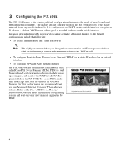
...Protocol over Ethernet (PPPoE) or a static IP address for more information on the PIX 506E. PDM is included for hosts on the PIX 506E protects your web browser. Refer to the Cisco PIX Device Manager Installation Guide for an outside interface to help you change or make ...sure JavaScript and Java are enabled in your inside interface. A default DHCP server address pool is a web browser-based configuration tool designed to acquire an IP address. PDM is configured to secure...
...Protocol over Ethernet (PPPoE) or a static IP address for more information on the PIX 506E. PDM is included for hosts on the PIX 506E protects your web browser. Refer to the Cisco PIX Device Manager Installation Guide for an outside interface to help you change or make ...sure JavaScript and Java are enabled in your inside interface. A default DHCP server address pool is a web browser-based configuration tool designed to acquire an IP address. PDM is configured to secure...
Quick Start Guide
Page 7
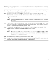
Accept the certificates and follow the instructions in the Startup Wizard. Step 3 Step 4 Check the ACT LED on the rear panel of the PIX Firewall (see Table 2 on the rear panel of the 192.168.1.0 network. Step 5 Step 6 Do not enter your PC has basic connectivity ... a Startup Wizard for initial configuration. For online help, click the Help button at the bottom of the PIX Firewall is assigned 192.168.1.1, so choose a different IP address. HTTPS (HTTP over SSL) provides a secure connection between your browser and the PIX Firewall that your username or password, just press Enter.
Accept the certificates and follow the instructions in the Startup Wizard. Step 3 Step 4 Check the ACT LED on the rear panel of the PIX Firewall (see Table 2 on the rear panel of the 192.168.1.0 network. Step 5 Step 6 Do not enter your PC has basic connectivity ... a Startup Wizard for initial configuration. For online help, click the Help button at the bottom of the PIX Firewall is assigned 192.168.1.1, so choose a different IP address. HTTPS (HTTP over SSL) provides a secure connection between your browser and the PIX Firewall that your username or password, just press Enter.
Quick Start Guide
Page 8
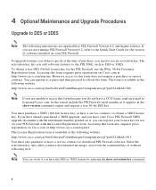
If you are not running PIX Firewall Version 6.2, refer to the PIX 506E, such as DES or 3DES. The activation key lets you add software features to the Quick Start Guide for the version of purchase, you do not have a service contract to licensing@cisco.com. To obtain a free DES (56-bit) license key ...for use on Cisco.com at the following...
If you are not running PIX Firewall Version 6.2, refer to the PIX 506E, such as DES or 3DES. The activation key lets you add software features to the Quick Start Guide for the version of purchase, you do not have a service contract to licensing@cisco.com. To obtain a free DES (56-bit) license key ...for use on Cisco.com at the following...
Quick Start Guide
Page 9
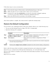
... for detailed command information and configuration examples: http://www.cisco.com/univercd/cc/td/doc/product/iaabu/pix/pix_sw/v_62/cmdref/index.htm The Cisco TAC website is complete, the system reloads to : http://www.cisco.com/tac 9 Reboot the PIX Firewall by powering it off and then on again..... From the CLI, enter the activation-key activation-key-four-tuple command, replacing activation-key-four-tuple with the activation key obtained from Cisco. After the key update is available to enter a new activation key. To access the TAC Website go to update the running configuration....
... for detailed command information and configuration examples: http://www.cisco.com/univercd/cc/td/doc/product/iaabu/pix/pix_sw/v_62/cmdref/index.htm The Cisco TAC website is complete, the system reloads to : http://www.cisco.com/tac 9 Reboot the PIX Firewall by powering it off and then on again..... From the CLI, enter the activation-key activation-key-four-tuple command, replacing activation-key-four-tuple with the activation key obtained from Cisco. After the key update is available to enter a new activation key. To access the TAC Website go to update the running configuration....
Quick Start Guide
Page 10
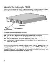
... the Cisco PIX Firewall and VPN Configuration Guide for a secure Telnet session. To do so, you must run a serial terminal emulator on the PIX Firewall. Use PDM or the console to configure SSH/Telnet access to use the command-line interface (CLI). 10 Alternative Ways to Access the PIX 506E You ...CLI using the console port on a PC or workstation. 67935 ACT LINK ETHERNET 1 ACT LINK ETHERNET 0 DC POWER USB CONSOLE INPUT DC POWER INPUT Cisco PIX 506E PC terminal adapter Blue console cable To connect a console for 9600 baud, 8 data bits, no parity, and 1 stop bit. By default, ...
... the Cisco PIX Firewall and VPN Configuration Guide for a secure Telnet session. To do so, you must run a serial terminal emulator on the PIX Firewall. Use PDM or the console to configure SSH/Telnet access to use the command-line interface (CLI). 10 Alternative Ways to Access the PIX 506E You ...CLI using the console port on a PC or workstation. 67935 ACT LINK ETHERNET 1 ACT LINK ETHERNET 0 DC POWER USB CONSOLE INPUT DC POWER INPUT Cisco PIX 506E PC terminal adapter Blue console cable To connect a console for 9600 baud, 8 data bits, no parity, and 1 stop bit. By default, ...
Quick Start Guide
Page 11
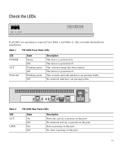
Check the LEDs POWER ACT NETWORK CISCO PIX 506E F I R E WA L L 67933 If all LEDs are passing traffic. 78186 Insert picture of 506/506E here. The device is powered off . The device is passing on the port. 11 No network interfaces are operating as expected (see Table 1... ACT LINK ETHERNET 1 ETHERNET 0 USB CONSOLE DC POWER INPUT Table 2 LED ACT LINK PIX 506E Rear Panel LEDs State On Off On Off Description Network activity is passing on the port. Table 1 PIX 506E Front Panel LEDs LED POWER ACT Network State Green Off Flashing green Off Flashing green Off ...
Check the LEDs POWER ACT NETWORK CISCO PIX 506E F I R E WA L L 67933 If all LEDs are passing traffic. 78186 Insert picture of 506/506E here. The device is powered off . The device is passing on the port. 11 No network interfaces are operating as expected (see Table 1... ACT LINK ETHERNET 1 ETHERNET 0 USB CONSOLE DC POWER INPUT Table 2 LED ACT LINK PIX 506E Rear Panel LEDs State On Off On Off Description Network activity is passing on the port. Table 1 PIX 506E Front Panel LEDs LED POWER ACT Network State Green Off Flashing green Off Flashing green Off ...
Quick Start Guide
Page 16
..., CCDP, CCIE, CCNA, CCNP, Cisco, the Cisco Certified Internetwork Expert Logo, Cisco IOS, the Cisco IOS logo, Cisco Press, Cisco Systems, Cisco Systems Capital, the Cisco Systems logo, Empowering the Internet Generation, Enterprise/Solver, EtherChannel, EtherSwitch, Fast Step, GigaStack, Internet Quotient, IOS, IP/TV, LightStream, MGX, MICA, the Networkers logo, Network Registrar, Packet, PIX, Post-Routing, Pre-Routing, RateMUX...
..., CCDP, CCIE, CCNA, CCNP, Cisco, the Cisco Certified Internetwork Expert Logo, Cisco IOS, the Cisco IOS logo, Cisco Press, Cisco Systems, Cisco Systems Capital, the Cisco Systems logo, Empowering the Internet Generation, Enterprise/Solver, EtherChannel, EtherSwitch, Fast Step, GigaStack, Internet Quotient, IOS, IP/TV, LightStream, MGX, MICA, the Networkers logo, Network Registrar, Packet, PIX, Post-Routing, Pre-Routing, RateMUX...
User Guide
Page 1
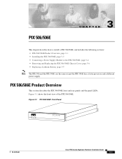
... ACT NETWORK CISCO PIX 506E F I R E WA L L 78-15170-02 Cisco PIX Security Appliance Hardware Installation Guide 3-1 PIX 506/506E CH A P T E R 3 This chapter describes how to install a PIX 506/506E, and includes the following sections: • PIX 506/506E Product Overview, page 3-1 • Installing the PIX 506/506E, page 3-3 • Connecting a Power Supply Module to the PIX 506/506E, page 3-4 • Removing and Replacing the PIX 506/506E Chassis Cover...
... ACT NETWORK CISCO PIX 506E F I R E WA L L 78-15170-02 Cisco PIX Security Appliance Hardware Installation Guide 3-1 PIX 506/506E CH A P T E R 3 This chapter describes how to install a PIX 506/506E, and includes the following sections: • PIX 506/506E Product Overview, page 3-1 • Installing the PIX 506/506E, page 3-3 • Connecting a Power Supply Module to the PIX 506/506E, page 3-4 • Removing and Replacing the PIX 506/506E Chassis Cover...
User Guide
Page 2
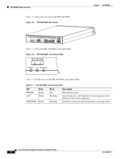
Cisco PIX Security Appliance Hardware Installation Guide 3-2 78-15170-02 Active indicator-On when the software image has been loaded on the security appliance. PIX 506/506E Product Overview Figure 3-2 shows the rear view of the PIX 506/506E front panel LEDs. On when at least one network interface is passing traffic. Table 3-1 PIX 506/506E Front Panel LEDs LED POWER ACT Color...
Cisco PIX Security Appliance Hardware Installation Guide 3-2 78-15170-02 Active indicator-On when the software image has been loaded on the security appliance. PIX 506/506E Product Overview Figure 3-2 shows the rear view of the PIX 506/506E front panel LEDs. On when at least one network interface is passing traffic. Table 3-1 PIX 506/506E Front Panel LEDs LED POWER ACT Color...
User Guide
Page 3
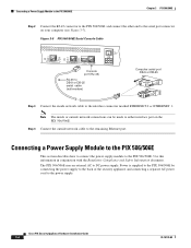
... either a DB-9 or DB-25 connector on a flat, stable surface. Installing the PIX 506/506E Place the PIX 506/506E on one DB-25 connector. 78-15170-02 Cisco PIX Security Appliance Hardware Installation Guide 3-3 Locate the serial cable from the accessory kit. Figure 3-4 PIX 506/506E Rear Panel LEDs ACT(ivity) ACT(ivity) LED LED LINK LINK LED LED...
... either a DB-9 or DB-25 connector on a flat, stable surface. Installing the PIX 506/506E Place the PIX 506/506E on one DB-25 connector. 78-15170-02 Cisco PIX Security Appliance Hardware Installation Guide 3-3 Locate the serial cable from the accessory kit. Figure 3-4 PIX 506/506E Rear Panel LEDs ACT(ivity) ACT(ivity) LED LED LINK LINK LED LED...
User Guide
Page 4
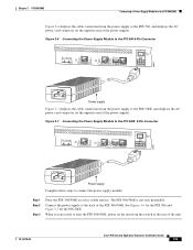
...PIX 506/506E. Cisco PIX Security Appliance Hardware Installation Guide 3-4 78-15170-02 Connecting a Power Supply Module to the PIX 506/506E This section describes how to connect the power supply module to DC power supply. Note The inside network cable to the interface connector marked ETHERNET 0 or ETHERNET 1. Power is supplied to the PIX 506/506E... by connecting the power supply to the back of the security appliance and connecting a separate AC power cord to either interface port on your ...
...PIX 506/506E. Cisco PIX Security Appliance Hardware Installation Guide 3-4 78-15170-02 Connecting a Power Supply Module to the PIX 506/506E This section describes how to connect the power supply module to DC power supply. Note The inside network cable to the interface connector marked ETHERNET 0 or ETHERNET 1. Power is supplied to the PIX 506/506E... by connecting the power supply to the back of the security appliance and connecting a separate AC power cord to either interface port on your ...
User Guide
Page 5
... Cisco PIX Security Appliance Hardware Installation Guide 3-5 Connect the power supply to the back of the PIX 506/506E. The PIX 506/506E is not rack mountable. See Figure 3-6 for the PIX 506 and Figure 3-7 for the PIX 506E. When you are ready to start the PIX 506/506E, power on a flat, stable surface. Chapter 3 PIX 506/506E Connecting a Power Supply Module to the PIX 506/506E...
... Cisco PIX Security Appliance Hardware Installation Guide 3-5 Connect the power supply to the back of the PIX 506/506E. The PIX 506/506E is not rack mountable. See Figure 3-6 for the PIX 506 and Figure 3-7 for the PIX 506E. When you are ready to start the PIX 506/506E, power on a flat, stable surface. Chapter 3 PIX 506/506E Connecting a Power Supply Module to the PIX 506/506E...
User Guide
Page 6
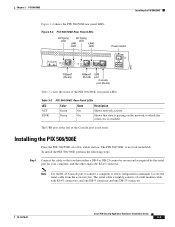
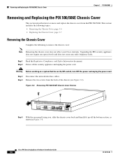
...4 Remove the two screws from the PIX 506/506E. Step 3 Disconnect the network interface cables. Warning Before working on a system that has an On/Off switch, turn OFF the power and unplug the power cord. Cisco PIX Security Appliance Hardware Installation Guide 3-6 78-15170-02... Step 1 Read the Regulatory Compliance and Safety Information document. Step 2 Power off the bottom section, as shown in Figure 3-8. Figure 3-8 Removing PIX 506/506E Chassis Cover Screws 119681 ACT LINK...
...4 Remove the two screws from the PIX 506/506E. Step 3 Disconnect the network interface cables. Warning Before working on a system that has an On/Off switch, turn OFF the power and unplug the power cord. Cisco PIX Security Appliance Hardware Installation Guide 3-6 78-15170-02... Step 1 Read the Regulatory Compliance and Safety Information document. Step 2 Power off the bottom section, as shown in Figure 3-8. Figure 3-8 Removing PIX 506/506E Chassis Cover Screws 119681 ACT LINK...
User Guide
Page 7
... for cooling the electronic components. Complete the following to replace the used battery. 78-15170-02 Cisco PIX Security Appliance Hardware Installation Guide 3-7 Place the PIX 506/506E on the security appliance. Replacing a Lithium Battery The PIX 506/506E has a lithium battery on a secure surface with the bottom of the cover are aligned with the front panel facing you set aside...
... for cooling the electronic components. Complete the following to replace the used battery. 78-15170-02 Cisco PIX Security Appliance Hardware Installation Guide 3-7 Place the PIX 506/506E on the security appliance. Replacing a Lithium Battery The PIX 506/506E has a lithium battery on a secure surface with the bottom of the cover are aligned with the front panel facing you set aside...
User Guide
Page 8
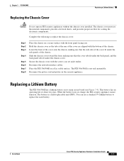
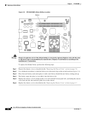
...page 3-6. Place the used batteries according to slide the battery out of explosion exists if the lithium battery is incorrectly replaced. Cisco PIX Security Appliance Hardware Installation Guide 3-8 78-15170-02 Install the new battery writing side up the cover tabs with the same or equivalent ... into place as described in the "Replacing the Chassis Cover" section on page 3-7. Replacing a Lithium Battery Figure 3-9 PIX 506/506E Lithium Battery Location Battery Chapter 3 PIX 506/506E Front 119680 Warning Danger of the metal clip on the circuit board (see Figure 3-9).
...page 3-6. Place the used batteries according to slide the battery out of explosion exists if the lithium battery is incorrectly replaced. Cisco PIX Security Appliance Hardware Installation Guide 3-8 78-15170-02 Install the new battery writing side up the cover tabs with the same or equivalent ... into place as described in the "Replacing the Chassis Cover" section on page 3-7. Replacing a Lithium Battery Figure 3-9 PIX 506/506E Lithium Battery Location Battery Chapter 3 PIX 506/506E Front 119680 Warning Danger of the metal clip on the circuit board (see Figure 3-9).

